

IM213M-MC Issue 5 © 2017 1
IM012M MECHANICAL INLINE
POSITIVE DISPLACEMENT FLOWMETER
INSTRUCTION MANUAL
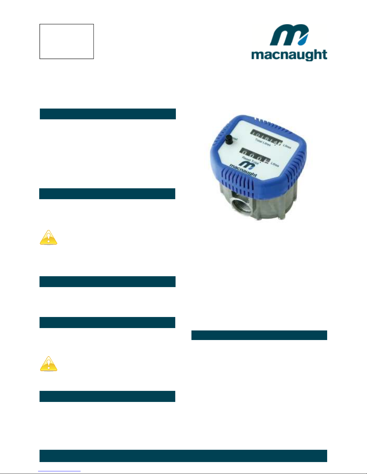
The IM012M has been designed specifically to
dispense lubricating oils, diesel and kerosene. This
high pressure, positive displacement-type meter is
suitable for all in-line and end-of-line applications and
features a rugged and robust register with Total and re
-settable Totals.
Please read and retain this instruction manual to
assist you in the operation and maintenance of this
quality product.
If you experience problems with this product, refer to the
Maintenance and Trouble Shooting sections of this
manual. If you require further assistance please contact
your local IM012M Distributor.
Macnaught recommends, that if you are using your meter
as an in-line application you should install a filter before
the inlet of the meter. Contact your local distributor for
further details.
1) Do not over tighten connections.
NOTE: If using in an in line application open the valve
slowly to prevent over spinning the rotors.
OPERATION
RESET BUTTON
The RESET button allows you to reset the Reset Total to
zero.
Ensure the fluid supply to the meter is disconnected
and the line pressure is released before disassembly.
REGISTER AND GEAR TRAIN REMOVAL
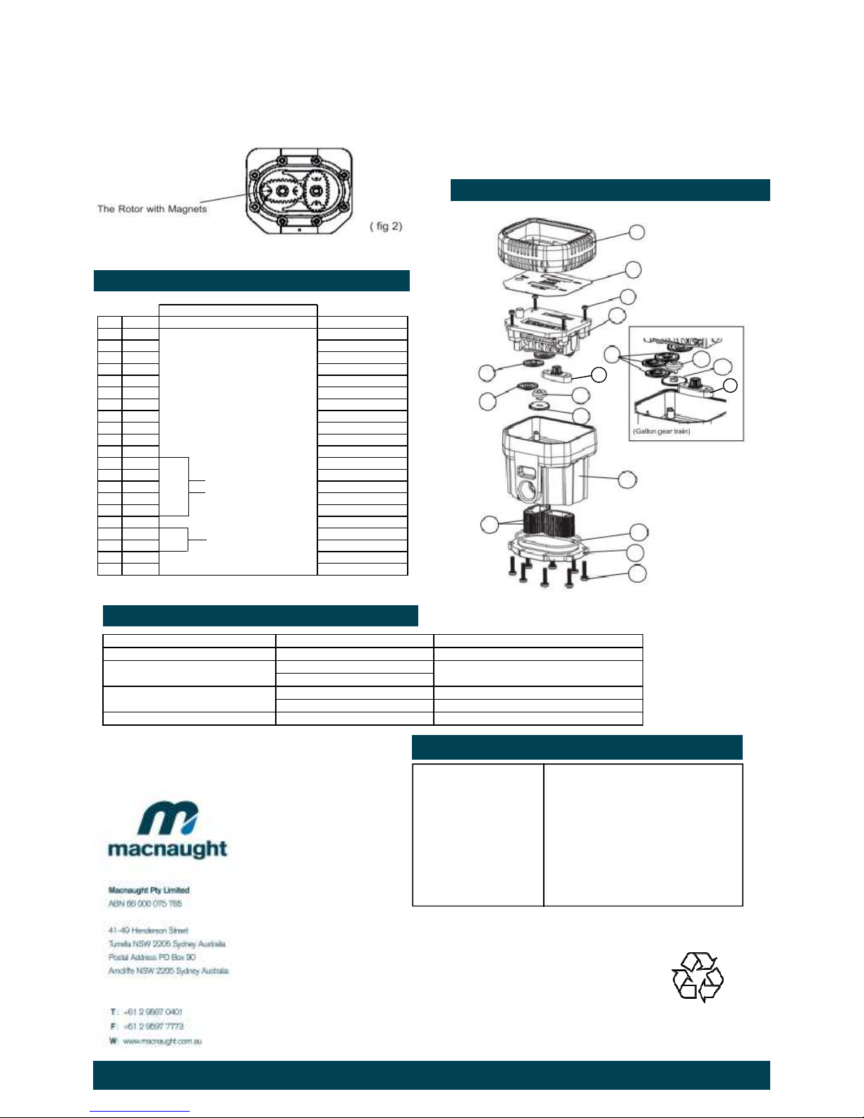
1) Remove the protective shroud (1).
2) Peel off the meter faceplate (2).
3) Remove the 4 x Philips head screws (3).
Note: Assembly is a reversal of the assembly procedure.
6) Replace the gears (7,6,5,8) litre and quart versions
and (3x5,7,8,9) gallon version.
Note: The register (4) is not repairable and will need to be
replaced if faulty or damaged.
7) Replace the register (4) and screws (3).
8) Fit a new faceplate (2) onto the register face (4).
9) Re-fit the protective shroud (1).
ROTOR REPLACEMENT
1) Remove the 8 x Philips head screws (14) from the
underside of the meter.
2) Remove the cover plate (13) and O-ring (12 ).
3) Remove both rotors (11) and inspect for any signs of
wear or damage. (Replace if worn or damaged).
NOTE: Ensure the rotor with the magnets is assembled on
the correct side (Ref fig 2).
The magnets in the rotor must face towards the
mechanical display .
1) Replace both rotors (11) positioned 90 Deg to each
other. (see fig 2). Check rotation by turning the rotors. If
the rotors do not rotate freely remove one of the rotors and
replace it correctly at 90 Deg to the other rotor. Re-check
the operation of the rotors.
IMPORTANT INFORMATION
CAUTION
4) Remove the register assembly (4).
5) Take careful note of the orientation of the gears on the
gear train, then carefully remove the gears
INTRODUCTION
GENERAL INFORMATION
INSTALLATION
Includes models
IM012M-01
IM012M-02
IM012M-02G
IM012M-02LMC
IM012M-03
IM213M-MC Issue 5 © 2017 2
2) Lightly grease the O-ring (12) and place it on the meter
body.
3) Clean the meter cover plate (13) and place it on the
body. Take care not to damage the o’ring (12).
4) Install the 8 screws (14) and tighten in a diagonal
pattern to1nm (0.73 ft-lb). Visual check the cap has been
pulled down evenly.
5) Test the meter by turning the rotors with a finger or by
applying low air pressure (No more than a good breath) to
the inlet port of the meter. This will confirm the meter is
operating correctly.
PARTS LIST
PARTS DIAGRAM
TROUBLE SHOOTING GUIDE
SPECIFICATIONS
Wetted components: Acetal, aluminium, nitrile (NBR), mild steel
*
A
ccu
r
a
cy:
+/- 1%
Flow Range: 1-30 litres/minute (0.26-8 US gal/min)
Max. working pressure: 6900 kPa / 1000 psi / 69 Bar
Inlet thread:
½” BSPP or NPT (F)
Outlet thread: ½” BSPP or NPT (F)
Operating temperature: -10°C (14°F) to +55°C (131°F)
Weight (approx): 490g (1.08lbs)
* When tested with lubrication oil @ 25°C. Allowances should be made for changes to these parameters.
Orde r fo r r ep lacem ent
Item No. off Part or Se t
Description
1 1 IM071BKS = (BLACK) Protector shroud set
1 1 IM071BUS = (BLUE) Protector shroud set
1 1 n/a Protector shroud set
1 1 n/a Protector shroud set
1 1 n/a Protector shroud set
2 1 IM166Ls (Litre) Face plate
2 1 IM166Qs (Quart) Face plate
2 1 IM166GS (Gallon) Face plate
3 4 n/a Screw set
4 IM168As (Litre / Quart) Register assembly
4 1 IM168A-Gs (Gallon) Register assembly
5 Bevel gear
6 1 IM176s (LITRE) incl 5,6,7,8,9 Gear set - Litres
7 1 IM177s (QUART) incl 5,6,7,8,9 Gear - Quarts
8 1 IM178s (Gallon) incl 3x5, 7,8,9 Gear - Gallons
9 1 Magnet housing assy
10 1 n/a - new meter required Meter body
11 2 IM181s - incl item 14 Rotor Set
12 1 O'ring (BS035)
13 1 n/a Cover plate
14 8 n/a screw set (M4 x16)
TROUBLE CAUSE REMEDY
Meter not accurate Flow rate not correct A djust flow rate to correct rate (1-30 Ltr/min)
No fluid passing through b) Dirt particles jamming the rotors b) Dismantle meter assembly and clean
the meter b) Dirt particles jamming the rotors ( ref er to meter disassembly )
The meter is not registering fluid output a) Damaged register assembly (4) a) Replace register assembly
b) Damaged gear or gears (5,6,7,8) b) Replace complete gear set.
Oil leak from coverplate (13) Damaged o’rings (12) Replace damaged o’ring
3
5
6
7
2
4
8
7
10
11
12
13
1
14
6
9
5
9
For Warranty Terms and Conditions see macnaught.com.au
For a list of Australian Service Centres see macnaught.com.au
Note:
This product should be disposed of according to all applicable local
and national government environment regulations and guidelines.
 Loading...