

IM213D-MC Issue 10 © 2017 Page 1 of 8
INSTRUCTION MANUAL
To the Owner
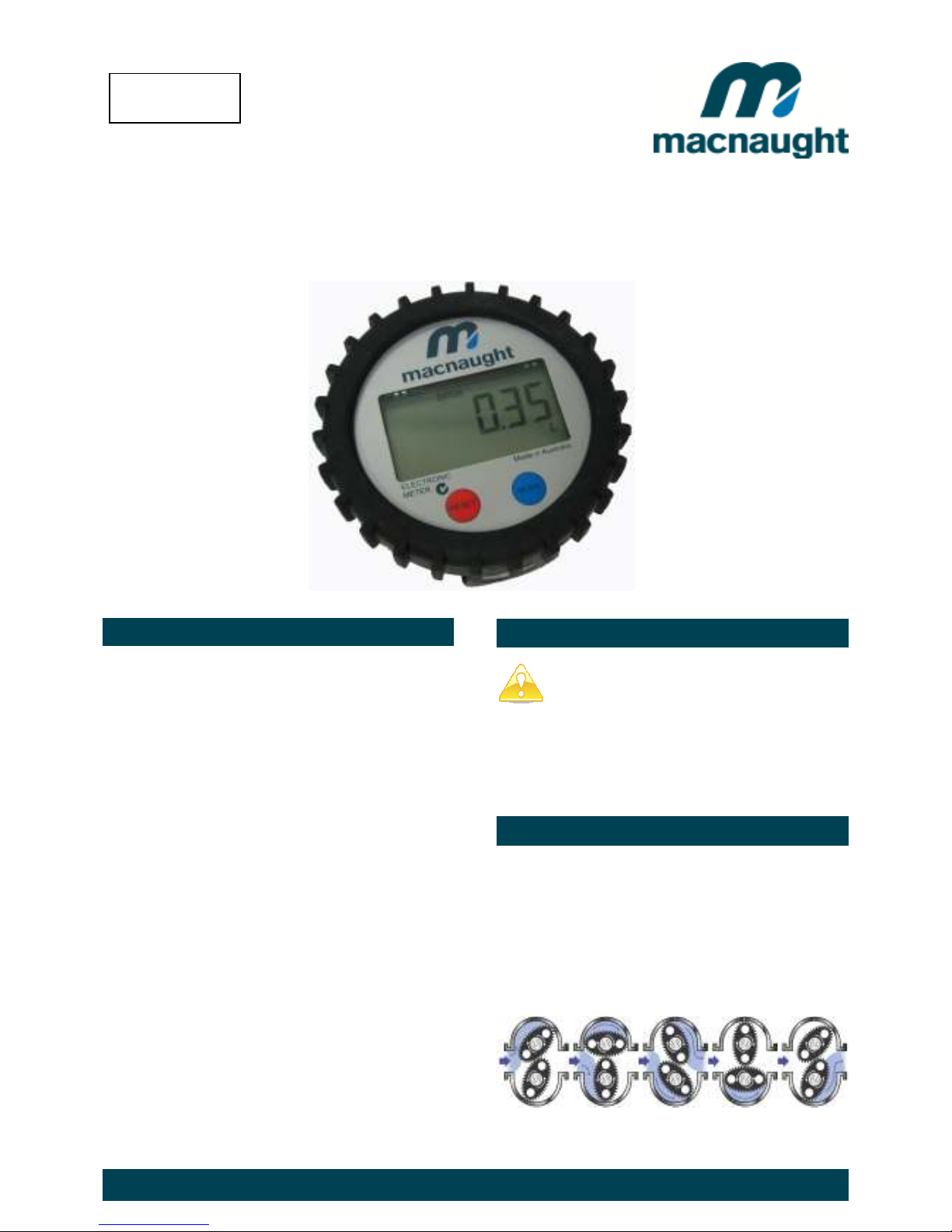
POSITIVE DISPLACEMENT FLOWMETER
Important Information
PLEASE READ THIS INFORMATION CAREFULLY
BEFORE USE.
Read and retain this instruction manual to assist you
in the operation and maintenance of this product.
If you have any problems with the meter, refer to the
maintenance and trouble shooting sections of this
manual.
This manual contains connection and operating
instructions for meters with Liquid Crystal displays
(LCD).
If you need further assistance, please contact your
local representative or distributor for advice.
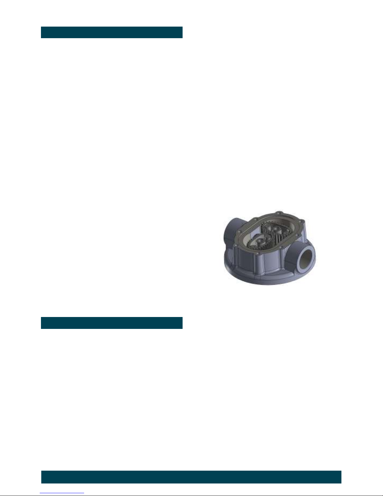
Operating Principle
WARNING
This Flow Meter has incorporated the oval rotor
principal into its design. This has proven to be a
reliable and highly accurate method of measuring
flow.
Exceptional repeatability and high accuracy over a
wide range of fluid viscosities and flow rates are
features of the oval rotor design. With a low pressure
drop and high pressure rating oval rotor flow meters
are suitable for both gravity and pump (in line)
Before use, confirm the fluid to be used is
compatible with the meter. Refer to Industry
fluid compatibility charts or consult your local
representative for advice.
When fluid passes through the meter the rotors
turn, as shown below. The magnets which are
located in the rotors will pass across the PCB
sensors.
A signal is generated which is then sent by the PCB
to the relevant LCD, or receiving instrument as a
Pulse Output.
IM012E (ELECTRONIC)
Include s m odels
IM012E-01
IM012E-02
Need Assistance?
Macnaught USA Inc (813) 628-5506 info@macnaughtusa.com

IM213D-MC Issue 10 © 2017 Page 2 of 8
Operational Overview
1. During normal operation the 6 Figure LCD display
will appear as per the example diagram below.
2. Pressing the blue ‘Mode’ button will enable the
operator to toggle between the following two
Display options.
•
Batch
•
Total
3. The ’Batch’ total can be reset by pressing the red
‘Reset’ button.
Please note:
This function resets the ‘Batch’ only. The
‘Total’ displayed is unable to be reset.
4. A ‘Sleep’ mode has been incorporated in the
meter to prolong battery life. The unit will activate
sleep mode after 30 secs without use.
2. Pressing the blue ‘Mode’ button will cycle through
options available
•
dEC .1
= 1 Decimal Place
•
dEC .22
= 2 Decimal Places
•
dEC .333
= 3 Decimal Places
3. To move to the next section (Unit) press the red
‘Reset’ button
Setting the Units for both Batch & Total.
1. The LCD will now display ‘
UNIT
’.
See ‘Operational Overview’.
2. Pressing the blue ‘Mode’ button will cycle through
the options of units that can be displayed for
Batch.
•
L
•
GAL
•
Qt
•
Pt
•
Oz
•
dL
3. Next press the red ‘Reset’ button to move onto
setting the ‘Total’ units. The availible unit options
are as shown above.
4. Once the required ‘Units’ have been selected
move to the next section (Calibration) by
pressing the Red ‘Reset’ button.
Programming Instructions
Note
Any changes made during the programming
phase will automatically be ‘Saved’ when the unit
is returned to the operation mode.
Accessing ‘Programming’ Menu
To enter in the programming ‘Menu’, press the reset
button for 5 secs.
Once in the programming menu the operator will be
able to access (and adjust) 3 programming
selections.
1- Setting Decimal Place
2- Display Units of measurement
3 - Calibration Mode
Setting the decimal place.
1.The unit will display the mode and the number of
Decimal Places currently set.
E.g. ‘
dEC .22
”
Calibration.
The calibration mode enables, in the case the
operator suspects the accuracy of the meter is in
question, the operator to dispense a known volume
of fluid through the meter (Test Volume)
This Test Volume is compared to the volume
measured by the meter (Measured Volume). The
meter will perform an ‘Auto Calibration’ if applicable.
1. The unit will display ‘
CALIBRATE
’ in the
lower left hand corner, and a number on
the main display.
The following options can be scrolled through by
pressing the blue Mode button
•
2
•
4
•
8
•
20
•
100
•
250
This number represents the ‘Test Volume’ to be
dispensed through the meter during Calibration.
IM213D-MC Issue 10 © 2017 Page 3 of 8
2. On selecting the ‘Test Volume’ press the blue
Mode button for 3 secs.
The meter will display ‘PURGE’ and ‘CALIBRATE’
will also start to flash.
3. Purge the system of air by running fluid through
the system.
4. Once purged of air the calibration process can be
started by pressing the blue Mode button.
The unit will display
RUN
and the ’Test Volume’.
E.g.
RUN 100
5. Run the Test Volume through the meter until
stipulated volume has been reached (e.g. 100).
6. Once this volume has been reached press the
blue Mode button to stop the test.
The unit will now compare the ‘Measured Volume’
to the ‘Test Volume’ and perform an ‘Auto
Calibration’ if the difference between the two
volumes are within ± 8% of each other.
Note:
If the difference between the two volumes is greater
than ± 8% of each other, the unit will display one of
the following messages..
•
ERROR LOW
•
ERROR HIGH
if these messages are displayed please contact your
Macnaught agent for advice.
Returning to ‘Operation’ Mode
At any stage the unit can be returned to the
‘Operation’ mode by pressing the red ‘Reset’ button
for approx. 3 secs.
Any program changes will automatically be saved.
Maintenance Procedures.
4. Remove the rotors (item 6) and inspect the
condition of each.
Also investigate if there is the presence of any
foreign material in the meter body, that may inhibit
the rotors performance
Reassembly
1. Please note, the design of the rotor and shaft
assembly ensures that the rotors can only be
re-installed with the correct orientation. (i.e. with
the magnets being in close proximity to the
Electronic module).
When replacing the rotors the top face of the
rotors should be flush with the sealing face of the
meter body. If they sit higher than the sealing
face remove, turn over and replace.
2. Replace the rotors (Item 6) onto the shafts at 90
degrees to each other (as per diagram below)
and check their operation by turning either of the
rotors.
If the rotors are not ‘in mesh’ correctly or do not
move freely, remove one of the rotors and replace
correctly at 90 degrees to the other rotor.
Programming Instructions
Disassembly
Ensure that the fluid supply to the meter is
disconnected, and the line pressure is released
before disassembly, with the exception for repair or
maintenance to the LCD or PCB where it is not
necessity to isolate the meter from flow. Refer to the
exploded parts diagram on subsequent pages for
item numbers.
1. Pull off protective boot (item 1) and unscrew the
four retaining screws (item 2) next remove the
Electronic Module (item 3)
2. Check for evidence of moisture into the electronic
housing. If there is evidence of this, check the
condition of the O-Ring (item 4)
3. Check the Rotors (item 6) rotate freely.
4. Replace the 0-Ring (item 7) into the groove of the
Meter Cap (item 8).
5. Replace the Meter Cap onto Meter Body (item 5)
Tighten Meter Cap screws (item 9) in a diagonal
sequence
E.g. 1, 5, 3, 7, 4, 8, 6, 2
6. Place the O-Ring (item 4) into the Electronic
Module (item 3) and mount the Electronic module
onto to the Meter Body
7. Replace and tighten the Retaining Screws (item 2)
in diagonal sequence.
8. Align and push on the protective boot (item 1) onto
the electronic module (item 3).
9. Before returning to service test the meter by
turning the Rotors with your finger. Or applying a
very low air pressure (no more than a good
breath) to the meter
3. To access the Rotor assembly, remove the 8
Meter Cap screws (item 9)

IM213D-MC Issue 10 © 2017 Page 4 of 8
Maintenance Procedures
Changing the Battery.
A ‘
Low Battery’
warning will be displayed on the
LCD screen when there is 5% power left.
The warning will remain active until the battery is
replaced.
1. See ‘Disassembly’ procedure.
Follow step 1 to isolate the Electronic module.
2. See ‘Photograph’ below.
Remove the PCB from clear plastic housing by
unscrewing the 3 retaining screws.
3. The battery can now be removed by placing a
screw driver into the slot (slot indicated by arrow)
on the PCB and easing the battery free from its
compartment.
4. Replace with a new CR2450 Lithium battery.
Yellow
Green
Reed Switch
Please Note: Not dependant on Polarity
Battery Slot

IM213D-MC Issue 10 © 2017 Page 5 of 8
Exploded Diagram
Spare part kits
Order for replacement
Item no No off Part or Set Description
1
1
IM215s Protective boot
2
7
Screw M3 x 8 Pan Hd
3
1
DKIT-IM012-MC Electronic module
4
1
O'ring (BS040)
5
1
n/a Body
6
2
MKIT-IM012-01 Rotor
7
1
O'ring (BS035)
8
1
n/a Cover plate
9
8
n/a Screw M4 x 16 Pan Hd

IM213D-MC Issue 10 © 2017 Page 6 of 8
Meter Dimensions
Notes

IM213D-MC Issue 10 © 2017 Page 7 of 8
Troubleshooting Guide
Problem Cause Remedy
Fluid will not flow
through meter
a) Foreign matter blocking rotors
b) Damaged rotors
c) Meter connections over tightened
d) Fluid is too viscous
a) Dismantle meter, clean rotors
b) Replacement rotor assembly required.
c) Re-adjust connections
d) See specifications for maximum viscosity
Reduced flow
through meter
a) Partially blocked
b) Fluid is too viscous
a) Check and clean meter.
b) See specifications for maximum viscosity
Meter reading
inaccurate
a) Fluid flow rate is too high or too low
b) Air in fluid.
c) Excess wear.
a) See specifications for minimum and maximum flow rates
b) Bleed air from system
c) Check meter body and rotors. (see instructions)
Meter not giving a
pulse signal
a) Faulty hall effect sensor
b) Faulty reed switch
c) Magnets failed
a) Replace PCB Board
b) Replace PCB Board
c) Replacement rotor assembly required
LCD register not
working
a) Battery flat
b) Faulty LC Display
a) Replace battery
b) Replace PCB module
WEEE Directive - Waste Electrical and Electronic Equipment
The WEEE Directive requires the recycling of waste electrical and electronic
equipment in the European Union.
Whilst the WEEE Directive does not apply to some of Macnaught’s products, we
support its policy and ask you to be aware of how to dispose of this product.
The crossed out wheelie bin symbol illustrated and found on our products signifies that
this product should not be disposed of in general waste or landfill.
Please contact your local dealer national distributor or Macnaught Technical Services
for information on product disposal.

IM213D-MC Issue 10 © 2017 Page 8 of 8
Product Specifications
* When tested with lubrication oil @ 25°C. Allowances should be made for changes to these parameters.
Accuracy + / - 0.5% of Reading
Type Oval Gear
Flow rate 1 Ltr -30 Ltr (0.26 - 8 US Gal) per minute
Maximum Pressure 6900kPa / 1000psi / 69 Bar
Suitable for use w ith : Engine Oil, Diesel Oil, Automatic Transmission Fluid (Maximum Viscocity SAE140),
Ethelene Glycol Based Anti-Freeze / Anti-Boil mixture (Max 50% w ater)
Wetted Materials Acetal, Aluminium, Steel, Nitrile Rubber
Connections 1/2" BSPT or 1/2" NPT
Maximum Temperature 55 deg C (131 deg F)
Minimum Temperature -14 deg C ( 6.8 deg F )
Maximum Viscosity 1000cP (Centipoise)
Re-settable 'Batch' Total 99999.9
Non-Resettable Total 999999
Note:
This product should be disposed of according to all applicable local
and national government environment regulations and guidelines.
For Warranty Terms and Conditions see macnaught.com.au
For a list of Australian Service Centres see macnaught.com.au
 Loading...