

Include s models
HG55-01
HG55-02
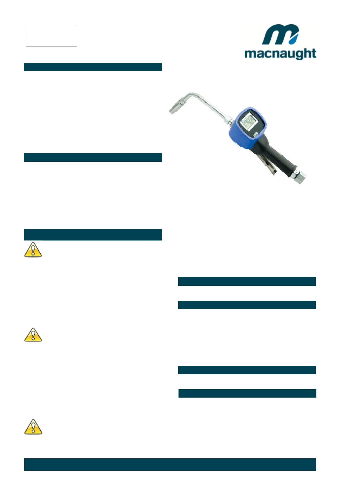
HG 55 OIL CONTROL GUN
WITH ELECTRONIC METER
INSTRUCTION MANUAL
INTRODUCTION
Thank you for purchasing a HG55 Electronic oil
control gun. Macnaught oil control guns have been
designed to accurately dispense, measure and control
oil flow. The control guns are suitable with engine oil,
gear oil, automatic transmission fluid, anti-freeze/antiboil and compatible fluids.
Please read and retain this instruction manual to
assist you in the operation and maintenance of this
quality product.
Note: Batteries are not pre-fitted and are included
separately inside the box. Please refer to “Battery
Replacement” on page 3 for correct procedure.
GENERAL INFORMATION
This manual assists you in operating and maintaining your
new oil control gun. The information contained will help
you ensure many years of dependable performance and
trouble free operation.
Please take a few moments to read through this manual
before installing and operating your new oil control gun. If
you experience problems with this product, refer to the
trouble shooting sections of this manual. If you require
further assistance please contact your local Macnaught
distributor or authorised Macnaught service centre.
IMPORTANT INFORMATION
READ THIS INFORMATION
CAREFULLY BEFORE USE.
Your safety is important to us. Please read and follow
all safety instructions listed inside.
Some of these instructions alert you to the potential
for personal injury. “Cautions” listed throughout this
manual advise of potential practices or procedures
which may cause damage to your equipment.
Ensure all operators have access to adequate
instructions about safe operating and maintenance
procedures.
WARNING
This oil control gun should not be used for in-line
installations or used with a manual a shut off nozzle.
The Safe operating pressure of this nozzle is 500 PSI
The line pressure between the pump and the
dispensing handle trigger valve must not exceed 1500
PSI (103 BAR). Please ensure an adequate pressure
relief valve is installed for operator safety.
The auto non drip nozzle MUST not be modified
CAUTION
Never point the nozzle at yourself or anyone else.
Never exceed the pressure rating of any component
installed in the System.
Before each use check all hoses for signs of wear,
leaks or loose fittings. Tighten all fluid connections
regularly and replace weak or damaged hoses.
Before attempting any repairs or maintenance of this
product firstly disconnect the air supply from the oil
pump, then release the oil line pressure by pressing
the lever on your oil control gun.
ASSEMBLY
Use Teflon tape (or suitable thread sealant ) when
connecting the oil control gun to an oil hose.
Outlet Nozzle.
The outlet nozzle can be fitted either “inline” (forward) or
on the outlet port “pistol style” located under the gun.
The long outlet tube should be used for the “inline” option.
The short adaptor should be used (instead of the long
outlet tube) when using the “pistol style” option.
Note: Use the threaded Plug supplied to seal the outlet
port not in use.
HANDLE OPERATION
To latch the handle, press the lever, push the button and
then release lever.
METER INTRODUCTION
Operating mode description
Sleep Mode: To minimise battery consumption the meter
will revert to sleep mode if left idle for more than 2 minutes,
and will automatically “power up” if the RESET, button is
pressed or there is flow through the meter.
Do not hit the oil control gun if it fails to operate. Refer
to “trouble shooting guide” or return the unit to your
nearest authorised service centre.
The Reset button can be used in two ways:
Press – Press and release the button.
Double click – Press and release the button twice quickly.
HG614 Issue 15 © 2017 1
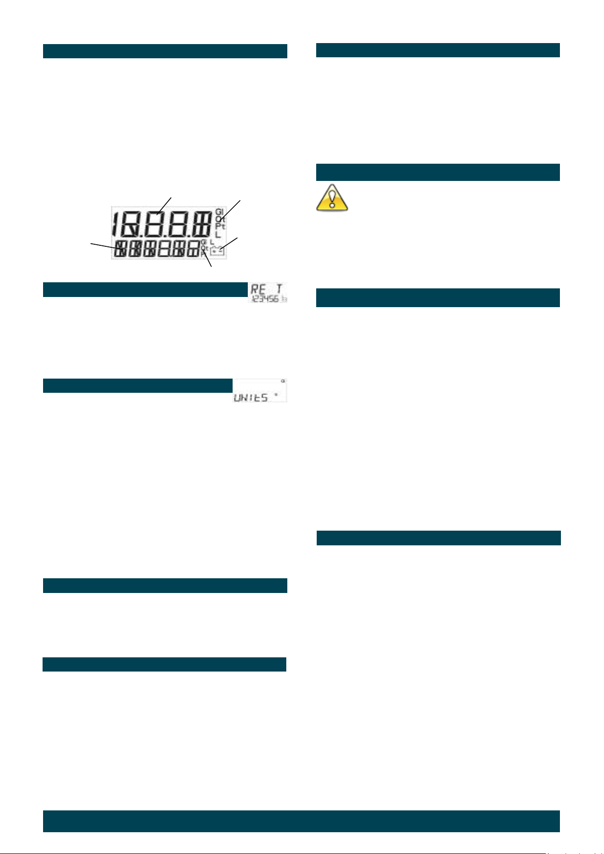
TOTALIZERS
There are three totalizers built in to your meter:
1) Reset-able batch total: Displays the current volume
dispensed. To reset batch total press the reset button.
2) Non reset-able accumulative total is located below
the batch total and displays the total volume the meter has
dispensed.
3) Reset-able accumulative total is hidden from view and
is used to track daily, weekly, or monthly usage.
Batch Total
Batch Total
Accumulative Total Units
TO VIEW OR RESET ACCUMULATIVE TOTAL:
1) Double click the Reset button (the display will enter the
reset-able total area.
2) To reset the reset-able total, press and release the
Reset button.
3) The display will return to manual mode after 5 seconds.
Batch Units
Low Battery
Warning
Error signal
If an error is detected, the following error code will appear
on the display.
Err1 – Sensor error
Err3 – Flowrate too high
Err4 – Calibration error
Err5 – Computer error
To reset the meter after an error signal press the Reset
button.
MAINTENANCE
CAUTION
Before carrying out any maintenance disconnect the
air supply to the pump and release the fluid pressure
in the system by pressing the lever on the control gun.
Inspect your oil control gun daily for any signs of damage.
Replace any damaged parts or components as required.
FIELD CALIBRATION
Field calibration will allow a +/- 5% adjustment to the
calibration.
1) In manual mode press the CAL button (located under
the calibration screw on the underside of the gun) for 5
seconds until Opt n 1 appears. (Refer item 16 page 4).
How to change the Units setting:
1) Press and hold down the Reset button for five seconds.
(The unit segment will appear)
2) Press the Reset button to cycle through the unit options.
3) Stop at the required setting.
Batch Total Accumulative Total
Litre Litre
Pint Gallon
Quart Gallon
Gallon Gallon
4) To store the selected units, press and hold down the
Reset button for five seconds until the batch and
accumulative totals appear. If the reset button is not held
down for 5 seconds, the original settings will be restored.
Low Battery
The battery segment will flash when the battery is low and
needs replacing.
Important: When the battery segment starts flashing
replace the battery as soon as possible, use only Alkaline
AA batteries.
Battery replacement
1) Remove the protective rubber boot.
2) Remove the battery cover screw located near the
Inline (forward) outlet port and remove the battery
cover.
3) Replace the two AA Alkaline batteries, note the battery
direction label inside the housing.
4) Inspect the battery cover seal for damage and replace if
necessary.
5) Replace battery cover and tighten screw.
2) Press the CAL button until F Cal appears.
3) Press the CAL button until F CAL starts flashing.
4) Using an accurate measuring container, fill the
container to the desired level. (e.g 5 litres)
5) Insert dispensed volume by:
a) Press reset button to change the numbers.
b) Press Cal button to move to the next number
c) Insert the correct dispensed value (e.g 5 litres)
d) Press Cal button for 5 seconds - F Cal will stop flashing.
6) To store press Reset for 5 seconds until 0.00 appears
CONTROL HANDLE DISASSEMBLY
Use a clean bench to carry out maintenance.
A) Remove the oil hose from the inlet swivel (26).
B) Unscrew and remove swivel (26) washer (24) and
o’ring (25) from the control gun inlet. Clean or replace the
strainer and o’ring.
Caution the swivel is under spring tension
C) Slide off the handle sleeve (23).
D) Remove valve spring (22), seal/valve body assembly
(20) and plunger (19).
Lever and Valve removal
A) Using a 2.5mm allen key, remove the 2 handle screws
(27).
B) Remove lever (29).
C) Remove the washer (18), “O”Ring (17), then push the
valve cam (14) from the gun body (13), and remove
“O”Ring (17).
HG614 Issue 15 © 2017 2

The meter is not registering fluid output
Remove the nozzle and blow out any dirt particles, replace if neces sary.
Oil leak from betw een the body casting
CONTROL HANDLE REASSEMBLY
A) Clean and inspect all parts. Replace any suspect,
worn or damaged components.
Note: Lightly lubricate the valve cam before assembly.
B) Place “O”Ring (17) onto valve cam (14).
Note: The cut out section in the middle of the valve cam
(14) must face the inlet swivel (26).
C) Replace the valve cam (14) into the body (13).
Note the orientation shown on the assembly drawing.
Fit the second “O”Ring (17) and washer (18).
D) Slide lever assembly (29) into position and replace
the two Allen screws (27). (Use Loctite or similar sealant).
E) Replace plunger (19).
Note: The end hole in the plunger must face the meter.
F) Assemble the seal/valve body (20), and spring (22) and
replace into the gun body.
Note: Install the spring, small end first.
G) Replace handle sleeve (23).
H) Replace washer (24), o’ring (25) swivel assembly
(26), and screw firmly into place (Use Loctite or similar
sealant).
Note: After assembly ensure the handle latch is operating
correctly.
METER DISASSEMBLY
1) Unscrew the swivel assembly (26) two complete
turns to allow easy disassembly and assembly of the
meter and remove boot (1).
2) Remove battery cover screw (3), the battery cover
(5) and batteries (7).
4) Carefully remove the computer module (2) from the
module housing (8).
Note: The computer module is non repairable and will
need to be replaced if damaged.
5) Remove the four Allen screws (15) from the
underside of the meter and remove the module housing
(8).
6) Remove the rotors (11) and the body ‘o’ ring (12).
3) Remove the three Phillips screws (9) and the
calibration port screw (16) from the underside of the meter.
METER REASSEMBLY
1) Clean and inspect all parts. Replace any suspect, worn
or damaged components.
2) Replace rotors (11) ( Refer to Fig 1 ).
(Fig 1)
Note: Ensure the rotor with the magnets is assembled with
the magnets facing up and positioned on the correct side
of the meter. Both rotors must also be positioned at 90deg
to each other ( Refer Fig 1 ).
3) Replace the gun body ‘o’ring (12).
4) Carefully position the module housing (8) on top of the
gun body (13), replace and tighten the four Allen screws
(15).
5) Ensure the handle latch is working correctly.
6) Test the oil control gun for correct operation.
7) Replace the computer module (2).
8) Replace and tighten the three Phillips head screws (9)
and calibration port screw (16).
9) Replace the two AA Alkaline batteries (7). (use the
directions on the label found inside the battery housing for
correct battery orientation).
10) Replace battery cover assembly (4,5,6) and tighten the
screw (3).
11) Firmly tighten the swivel assembly (26).
12) Replace the boot (1).
13) Test oil control gun for correct operation.
TROUBLE SHOOTING GUIDE
No fluid passing through a) Blocked strainer a) Clean or replace strainer
the meter b) Dirt particles jamming the rotors b) Dismantle meter assembly and clean
Meter display reads Err 1 Sensor error Press the reset button to reset the computer.
Meter display reads Err 3 Flow rate to high Adjust the flow rate to 1–30 l/mim ( 0.26-8 US gal/min )
Meter display reads Err 4 Calibration error Press the reset button to reset the computer
Meter display reads Err 5 Computer error Press the reset button to reset the computer
Constant oil leak from the nozzle Damaged plunger seal (20) Replace plunger seal ( check for damage )
Intermittent drip from the nozzle Dirt in the nozzle
Oil leak from the lever ass embly area Damaged o’rings (17) Replace damaged o’rings
and the computer module casting
Low flow rate Blocked strainer (32) Replace strainer
Oil leaking from the sw ivel inlet Damaged o’ring or sw ivel Replace sw ivel
TROUBLE CAUSE REMEDY
c) Damaged plunger seal c) Replace damaged plunger seal
a) Flat battery a) Replace battery
b) No signal from the magnets b) Check magnets and replace rotors if required
c) Damaged computer module c) Replace computer module
Damaged o’ring (12) Replace damaged o’ring
HG614 Issue 15 © 2017 3
( ref er to meter disassembly )
(If the error repeats, c heck the magnets in the rotor)
Eliminate air from the sys tem
Note: Alw ays pr es s th e re set button to re se t the com pute r

SPARE PARTS DIAGRAM SPARE PARTS LIST
Orde r for re placem en t
HG50-1K (KIT A) M ajor s er vice kit
HG50-2K (KIT B) incl Valve se rvice k it
1
2
3
4
7
8
Calibration Screw
9
6
5
10
12
17
16
11
17
14
18
13
27
19
28
20
30
15
27
29
* ORDER HGREX for a Rigid Tube Extension incl. outlet adapter set (not shown).
* ORDER HGNZL for a Automatic non Drip nozzle
WEEE Directive - Waste Electrical and Electronic Equipment
31
* ORDER HGFNZ for a Flexible Extension assembly, incl.
flexible extension, non drip nozzle and adaptor (not shown).
22
23
26
32
24
33
25
Item No. off Part or se t Kit ref Des cript ion
1 1 HG381BKs Electronic boot (STD)
2 1 HG369As Electronic module
3 1 A Battery cover s crew
4 1 A O'ring (BS007)
5 1 Battery cover
6 1 A Battery cover insert
7 2 n/a AA Alkaline batteries
8 1 n/a Module housing
9 3 A M3x6 Taptite screw s
10 2 Magnets
11 2 HG005s Oval gear set
12 1 A O'ring (BS035)
13 1 n/a - new gun req'd Gun body
14 1 A & B V alve cam
15 4 A M6x20 Taptite screw s
16 1 A & B Calibration screw
17 2 A & B O'ring (BS111)
18 1 A & B Washer
19 1 A Plunger
20 1 A & B V alve body and seal assy
22 1 A & B V alve spring
23 1 Handle sleeve
24 1 A & B Washer
25 1 A & B O'ring (BS117)
26 1 HG040As incl item 24 / BS117 Sw ivel assy (BSP)
26 1 HG043As incl item 24 / BS117 Sw ivel assy (NPT)
27 2 A & B M4x6 Counter sink screw s
28 1 Push button manual
29 1 HG010As Lever latching
30 1 A Button spring
31 1 A Lever plug
32 1 A & B Mesh
33 1 A & B O'ring (BS113)
The WEEE Directive requires the recycling of waste electrical and electronic equipment in the European
Union. Whilst the WEEE Directive does not apply to some of Macnaught’s products, we support its policy
and ask you to be aware of how to dispose of this product. The crossed out wheelie bin symbol illustrated
and found on our products signifies that this product should not be disposed of in general waste or landfill.
Please contact your local dealer national distributor or Macnaught Technical Services for information on
product disposal.
SPECIFICATIONS:
Accuracy:
Flow Range:
Maximum Supply Pressure:
Pressure Loss:
Weight:
Swivel Inlet:
Outlet:
Operating Temperature:
Storage Temperature:
Battery:
Wetted Parts:
Fluid Compatibility:
Dimensions:
+ - 0.5% (of Reading) (ISO100 @ 10 l/min)
1-30 l/min ( 0.26 – 8 US gal/min)
103.50 BAR / 10350kPa / 1500 PSI
1Bar/ 100kPa / 14.4PSI @ 12 l/min (3.2 US gal/min) with calibration fluid (6 Centipoise
Viscosity) without extension.
1.16kg ( 2.55lbs)
½” BSPT or ½” NPT
3/8” NPT
-0 to +50 degrees Celsius (32 – 122 degrees F)
-10 to +60 degrees Celsius (14 – 140 degrees F)
2 x 1.5Volt AA Batteries ( Alkaline batteries are essential for HG60 version)
Aluminium, Acetal, Steel, Nitrile Rubber
Engine Oil, Diesel Oil, Automatic Transmission Fluid, Anti-freeze / Anti-Boil Mixture.
(Maximum Viscosity SAE140)
25.8cm (10inch) Long x 9.5 cm ( 3.7inch) High, 11cm(4.33inch) wide (Dimensions without
extension)
Note:
This product should be disposed of according to all applicable local
and national government environment regulations and guidelines.
For Warranty Terms and Conditions see macnaught.com.au
For a list of Australian Service Centres see macnaught.com.au
HG614 Issue 15 © 2017 4
 Loading...