

HG616 Issue 10 © 2017 1
HG 20R(Rigid) & HG20F (Flexible)
OIL CONTROL GUNS
INSTRUCTION MANUAL
INTRODUCTION
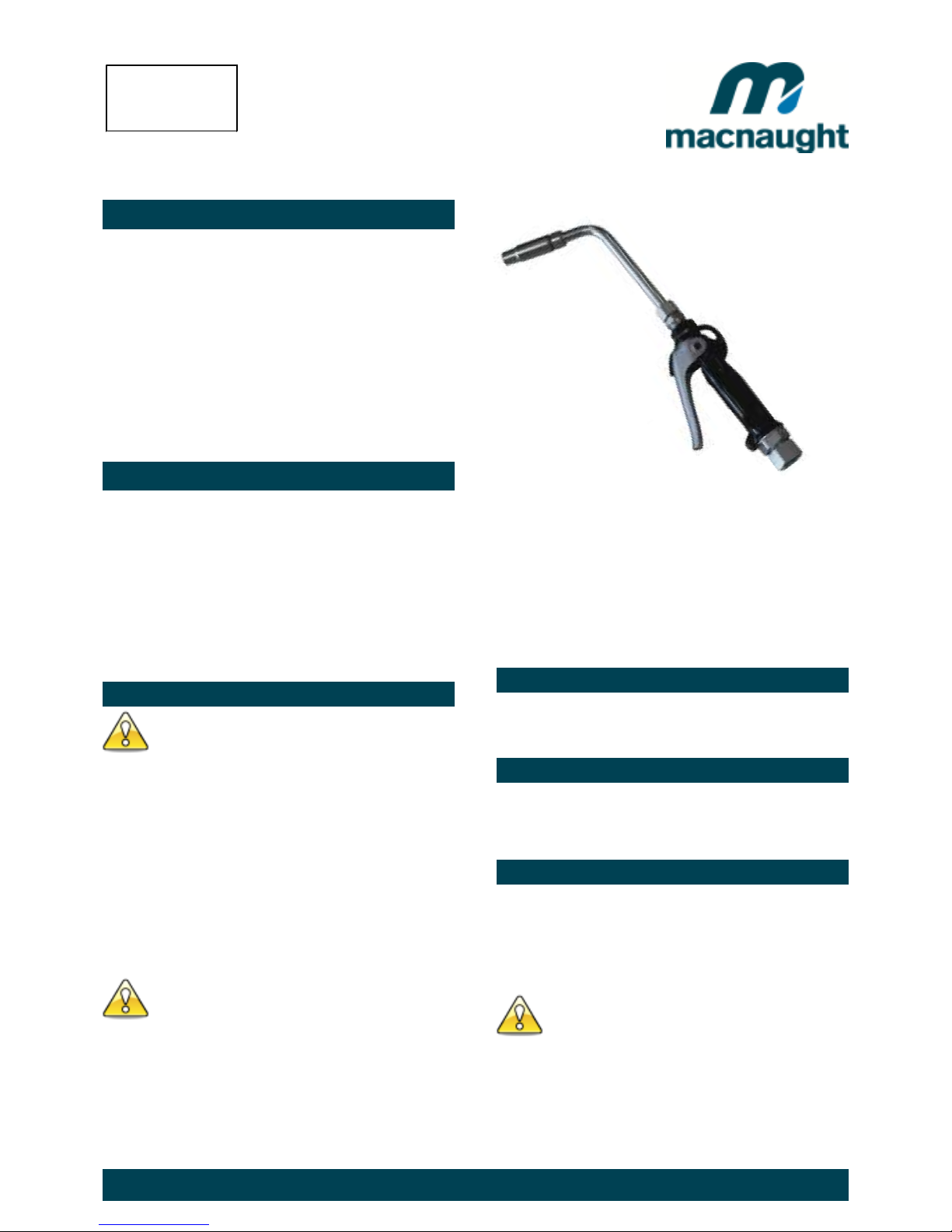
Thank you for purchasing a Macnaught oil dispensing
gun complete with either a flexible or rigid extension.
The Macnaught oil dispensing guns have been
designed for use with engine oil, gear oil, automatic
transmission fluid, anti-freeze/anti-boil and compatible
fluids.
Macnaught also manufacture a complete range of ratio
oil pumps and retractable oil hose reels, greasing
equipment and accessories to fulfil all your fluid
handling and greasing needs requirements.
Please read and retain this instruction manual to
assist you in the operation and maintenance of this
quality product.
GENERAL INFORMATION
This manual assists you in operating and maintaining your
new oil control gun. The information contained will help
you ensure many years of dependable performance and
trouble free operation.
Please take a few moments to read through this manual
before installing and operating your new oil control gun. If
you experience problems with this product, refer to the
trouble shooting sections of this manual. If you require
further assistance please contact your local Macnaught
distributor or authorised Macnaught service centre.
IMPORTANT INFORMATION
Your safety is important to us. Please read and follow
all safety instructions listed inside.
Some of these instructions alert you to the potential
for personal injury. “Cautions” listed throughout this
manual advise of potential practices or procedures
which may cause damage to your equipment.
Ensure all operators have access to adequate
instructions about safe operating and maintenance
procedures.
Do not exceed the maximum working pressure of 6900
kPa / 1000 psi / 69 bar.
Do not hit the oil control gun if it fails to operate. Refer
to “trouble shooting guide” or return the unit to your
nearest authorised service centre.
Never point the nozzle at yourself or anyone else.
Never exceed the pressure rating of any component
installed in the System.
Before every use check all hoses for signs of wear,
leaks or loose fittings. Tighten all fluid connections
regularly and replace weak or damaged hoses.
Before attempting any repairs or maintenance of this
product firstly disconnect the air supply from the oil
pump, then release the oil line pressure by squeezing
the lever on your oil control gun.
ASSEMBLY
Use Teflon tape (or suitable thread sealant ) when
connecting the oil control gun to an oil hose.
OUTLET NOZZLE OPERATION
When fluid flows through the gun the outlet nozzle will
automatically open. When the fluid flow stops the outlet
nozzle will automatically shut.
HANDLE OPERATION
To latch the handle, squeeze the lever, push the button
and then release lever.
To release the latch in manual mode simply squeeze and
release lever.
READ THIS INFORMATION
CAREFULLY BEFORE USE.
CAUTION
Before carrying out any maintenance disconnect the
air supply to the pump and release the fluid pressure
in the system by pressing the lever on the control gun.
Inspect your oil control gun daily for any signs of damage.
Replace any damaged parts or components as required.
CAUTION
Include s m ode ls
HG20F-01
HG20R-01
HG20R-02
HG616 Issue 10 © 2017 2
CONTROL HANDLE DISASSEMBLY
Use a clean bench to carry out maintenance.
A) Remove the oil hose from the control gun inlet swivel
(10).
B) Unscrew and remove swivel (10) washer and o’ring
from the control gun inlet. (Clean or replace the swivel
strainer and o’ring if required).
The swivel is under spring tension
C) Remove valve spring (9), seal/valve body assembly (8).
and plunger (7).
D) Remove the screw (15), then unclip and remove the
trigger guard (16).
LEVER and VALVE REMOVAL
A) Using a 2.5mm allen key, remove the 2 handle screw
(2).
B) Remove lever (11), ease downwards.
C) Remove the washer (5), “O”Ring (3), then push the
valve cam (4) from the gun body (6), and remove “O”Ring
(3).
Note: If the plunger has not been removed the cam will not
release from the body.
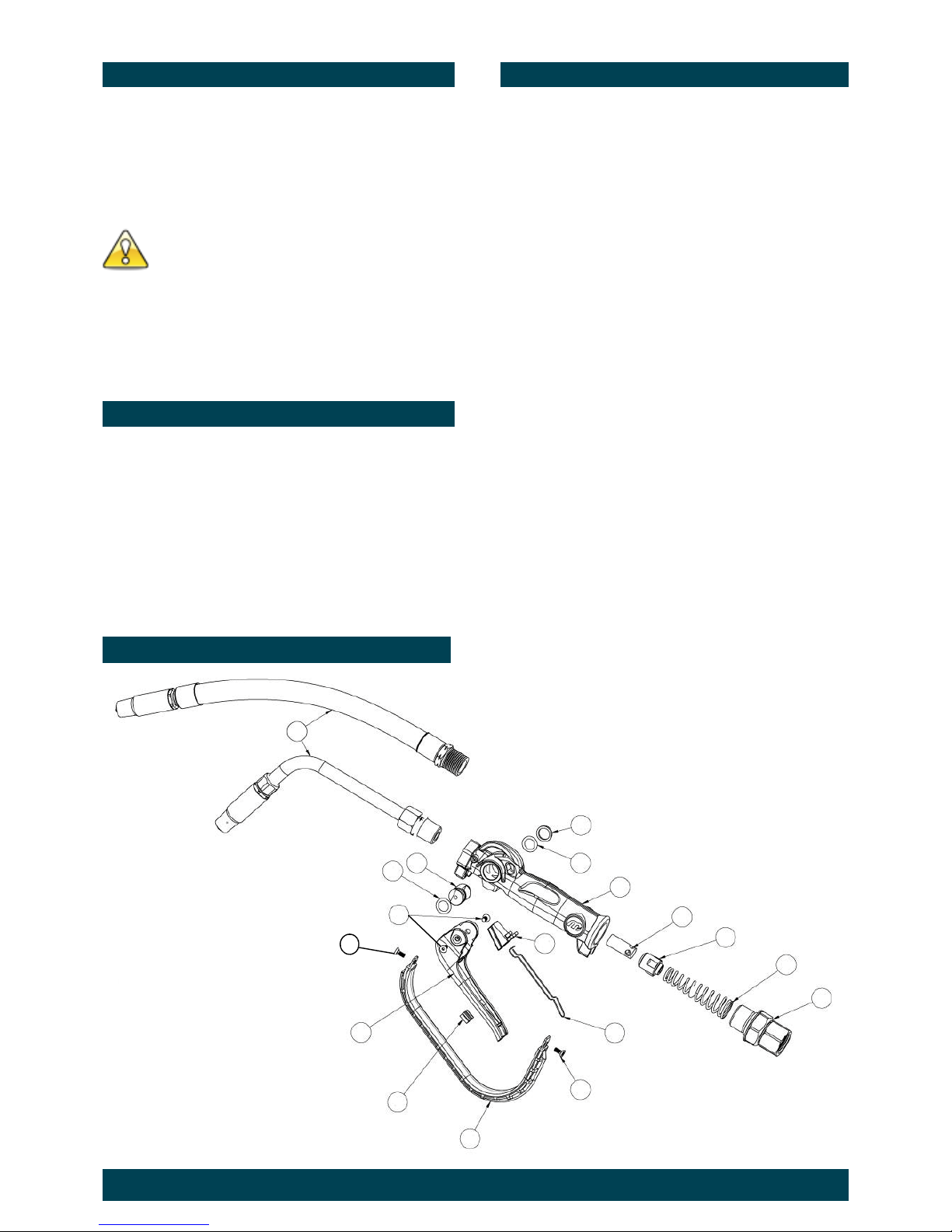
PARTS DIAGRAM
CONTROL HANDLE REASSEMBLY
A) Clean and inspect all parts. Replace any suspect,
worn or damaged components.
Note: Lightly lubricate the valve cam before assembly.
B) Place “O”Ring (3) onto valve cam (4).
Note: The cut out section in the middle of the valve cam
(4) must face the inlet swivel (10).
C) Replace the valve cam (4) into the body (6). Note the
orientation shown on the assembly drawing. Fit the
second “O”Ring (3) and washer (5).
D) Slide lever assembly (11) into position and replace the
two Allen screws (2). (Use Loctite or similar sealant).
E) Replace plunger (7).
Note: The end hole in the plunger must face the gun
outlet.
F) Replace the seal/valve body assembly (8), and
spring (9) and replace into the gun body (6).
Note: Install the spring, small end first.
G) Re-fit the trigger guard (16) and replace screw (15)
H) Replace washer, o’ring on to the swivel assembly (10),
and screw firmly into place (Use Loctite or similar
sealant).
Note: After assembly ensure the handle latch is operating
correctly.
CAUTION
2
6
10
5
3
1
14
9
12
15
11
8
7
4
13
16
3
15

HG616 Issue 10 © 2017 3
SPARE PARTS LIST
TROUBLE SHOOTING GUIDE
TROUBLE CAUSE REMEDY
No fluid passing through the gun Blocked strainer Clean or replace strainer
Constant oil leak from the nozzle Damaged plunger seal Replace plunger seal ( check for damage )
Intermittent drip from the nozzle Dirt in the nozzle Remove the nozzle and blow out any dirt particles,
replace if necessary.
Oil leak from camshaft area Damaged o’rings Replace damaged o’rings
Low flow rate Blocked strainer Replace strainer
Oil leaking from the swivel inlet Damaged o’ring or swivel Replace damaged o’ring or swivel
Order for replacement
Item No off Part or Set Kit Ref Description
HG20-1K (Kit A) Seal Kit
1 1 IM078As Flexible Extension with Auto Nozzle
1 1 HG510As Rigid Extension with Auto Nozzle
2 2 A Screw (M4 x 8 CSK)
3 2 A O-ring BS111
4 1 A Camshaft
5 1 A Washer
6 1 n/a - new gun reqired Body Casting
7 1 A Plunger Cage
8 1 A Valve Seal
9 1 A Spring
10 1 HG040As Swivel Assembly (BSP)
10 1 HG043As Swivel Assembly (NPT)
11 1 Handle (Latching)
12 1 HG022s A Lever Plug
13 1 A Push Button - Auto
14 1 A Button Spring
15 2 A Screw
16 1 Handle guard

HG616 Issue 10 © 2017 4
PRODUCT SPECIFICATIONS:
Flow Range:
1-25 l/min ( 0.26 – 6.6 US gal/min)
Maximum Pressure:
69 BAR / 6900 kPa / 1000 PSI
Swivel Inlet:
1/2” BSPT or 1/2” NPT
Outlet:
1/2” NPT
Weight:
0.8 kg
Wetted Parts:
Aluminium, Mild Steel, Nitrile Rubber
Fluid Compatibility:
Engine Oil, Diesel Oil, Automatic Transmission Fluid,
Anti-freeze/Anti-Boil - (Maximum Viscosity SAE140)
For Warranty Terms and Conditions see macnaught.com.au
For a list of Australian Service Centres see macnaught.com.au
Note:
This product should be disposed of according to all applicable local
and national government environment regulations and guidelines.
 Loading...