

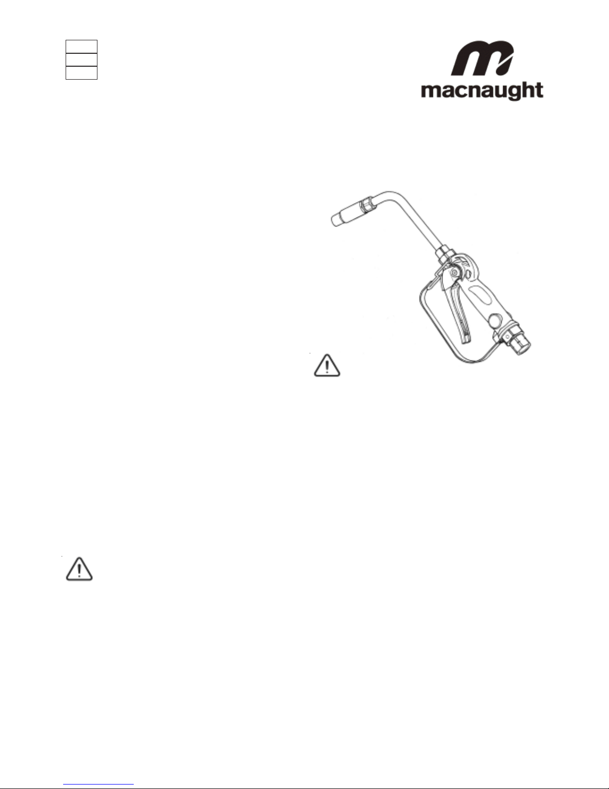
HG 20R(Rigid) and HG20F (Flexible) OIL CONTROL GUNS
0003
INTRODUCTION
Thank you for purchasing a Macnaught oil dispensing gun
complete with either a flexible or rigid extension. The
Macnaught oil dispensing guns have been designed for use
with engine oil, gear oil, automatic transmission fluid,
anti-freeze/anti-boil and compatible fluids.
Macnaught also manufacture a complete range of ratio oil
pumps and retractable oil hose reels, greasing equipment
and accessories to fulfill all your fluid handling and greasing
needs requirements.
GENERAL INFORMATION
This manual assists you in operating and maintaining your
new oil control gun. The information contained will help you
ensure many years of dependable performance and trouble
free operation.
Please take a few moments to read through this manual before
installing and operating your new oil control gun. If you
experience problems with this product, refer to the trouble
shooting sections of this manual. If you require further
assistance please contact your local Macnaught distributor
or authorised Macnaught service centre.
IMPORT ANT INFORMA TION
READ THIS INFORMATION
CAREFULL Y BEFORE USE.
Your safety is important to us. Please read and follow all
safety instructions listed inside.
Some of these instructions alert you to the potential for
personal injury. “Cautions” listed throughout this manual
advise of potential practices or procedures which may
cause damage to your equipment.
Ensure all operators have access to adequate instructions
about safe operating and maintenance procedures.
Do not exceed the maximum working pressure of 6900
kPa / 1000 psi / 69 bar .
CAUTION
Do not hit the oil control gun if it fails to operate. Refer to
“trouble shooting guide” or return the unit to your nearest
authorised service centre.
Never point the nozzle at yourself or anyone else.
Never exceed the pressure rating of any component
installed in the System.
Before every use check all hoses for signs of wear, leaks
or loose fittings. Tighten all fluid connections regularly and
replace weak or damaged hoses
Before attempting any repairs or maintenance of this
product firstly disconnect the air supply from the oil pump,
then release the oil line pressure by squeezing the lever on
your oil control gun.
ASSEMBLY
Use teflon tape (or suitable thread sealant ) when connecting
the oil control gun to an oil hose.
1
OUTLET NOZZLE OPERA TION
When fluid flows through the gun the outlet nozzle will
automatically open. When the fluid flow stops the outlet
nozzle will automatically shut
HANDLE OPERATION
To latch the handle, squeeze the lever, push the button and
then release lever.
To release the latch in manual mode simply squeeze and
release lever.
Please read and retain this instruction manual to assist
you in the operation and maintenance of this quality product.
INSTRUCTION MANUAL
HG616
0206
Before carrying out any maintenance disconnect
the air supply to the pump and release the fluid
pressure in the system by pressing the lever on the
control gun.
Inspect your oil control gun daily for any signs of damage.
Replace any damaged parts or components as required.
CONTROL HANDLE DISASSEMBLY
Use a clean bench to carry out maintenance.
A) Remove the oil hose from the control gun inlet swivel
(21).
B) Unscrew and remove swivel (21) washer (19) and o’ring
(20) from the control gun inlet. (Clean or replace the
swivel strainer and o’ring if required).
Caution the swivel is under spring tension
D) Remove the screw (23), then unclip and remove the
trigger guard (22).
C) Remove valve spring (18), seal/valve body assembly (17).
and plunger (15).
LEVER and VALVE REMOVAL
A) Using a 2.5mm allen key, remove the 2 handle screws
(10).
B) Remove lever (11), ease downwards.
C) Remove the washer (7), “O”Ring (8), then push the valve
cam (9) from the gun body (6), and remove “O”Ring (8).
CONTROL HANDLE REASSEMBLY
A) Clean and inspect all parts. Replace any suspect, worn or
damaged components.
Note: Lightly lubricate the valve cam before assembly.
B) Place “O”Ring (8) onto valve cam (9).
Note: The cutout section in the middle of the valve cam (9)
must face the inlet swivel (21).
C) Replace the valve cam (9) into the body (6). Note the
orientation shown on the assembly drawing. Fit the
second “O”Ring (8) and washer (7).
D) Slide lever assembly (11) into position and replace the two
allen screws (10). (Use Loctite or similar sealant).
E) Replace plunger (15).
Note: The end hole in the plunger must face the gun outlet.
F) Replace the seal/valve body assembly (17), and spring
(18) and replace into the gun body (6).
Note: Install the spring, small end first.
H) Replace washer (19), o’ring (20) on to the swivel assembly
(21), and screw firmly into place (Use Loctite or similar
sealant).
Note: After assembly ensure the handle latch is operating
correctly.
2
G) Re-fit the trigger guard (22) and replace screw (23).
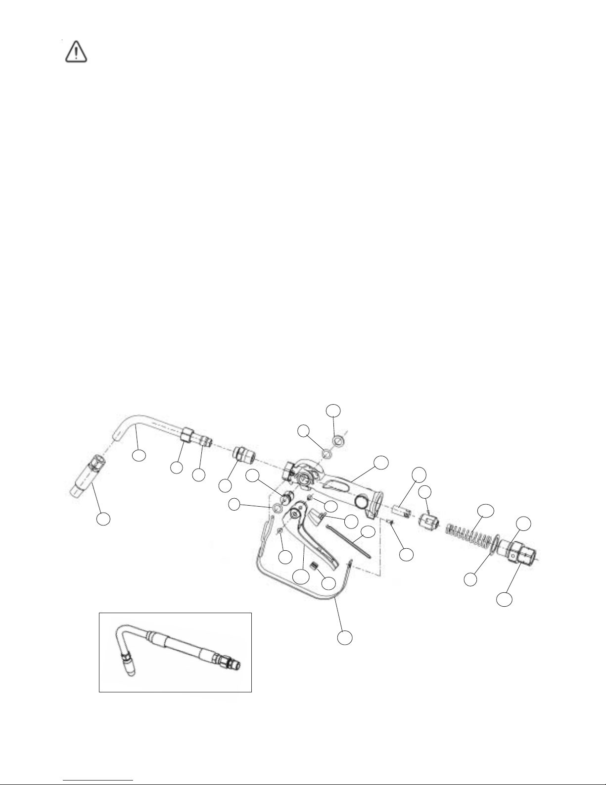
P ARTS DIAGRAM
HGFNZ
1
2
3
4
5
6
7
8
9
10
11
8
10
12
13
14
15
18
19
20
21
22
23
Note: If the plunger has not been removed the cam will not
release from the body.
17

3
SPARE PARTS LIST
** Order HGFEX for Flexible Extension
TROUBLE SHOOTING GUIDE
TROUBLE CAUSE REMEDY
No fluid passing through the g un Block ed strainer Clean or replace str ainer
Constant oil leak from the nozzle Damaged plunger seal Replace plunger seal ( chec k for damage )
Intermittent dr ip f r om t he nozzle Dirt in the noz zle (50) Remove t he nozzle and blow out any dirt par ticles,
replace if nec essary .
Oil leak from the lever assembly ar ea
Damaged o’rings (19) Replace damaged o’rings
Low flow r ate Block ed strainer ( 37) Replace strainer
Oil leak ing f r om the swiv el inlet Damaged o’ring or swive l Replace damaged o’ring or swiv el
ORDER FOR REPLACEMENT
ITEM PART NO. NO OFF PART/SET No KIT. REF DESCRIPTION
HG20- 1 K (Kit A) Se a l Kit
1 HG570 1 HG570s Automatic Nozzle
2 HG510 1 Ridgid Tube
3 N429 1 HG505 s Compres sion Fitting
4N428 1 Olive
5 HG512 1 1/2" NPT Outlet Adaptor
6 HG265 1 HG265s Body Casting
7 HG036 1 A Washer
8BS111 2 A O'Ring
9HG030 1 A Camshaft
10 N55 2 A C'sk Sc rew
11 HG266 1 HG010As Handle (Latching)
11 HG269 1 HG012As Handle (Non-Latc hing)
12 HG025 1 Lever Plug
13 HG024 1 HG022s Button Spring
14 HG022 1 Lever Button
15 HG032 1 Plunger Cage
17 HG038 1 HG032s Valve body and Seal assy
18 HG033 1 A Spring
19 HG045 1 A Was her
20 BS117 1 A O'Ring
21 HG040A 1 HG040As incl HG045 / BS117 Swivel Assembly (BSP)
21 HG043A 1 HG043As incl HG045 / BS117 Swivel Assembly (NPT)
22 HG268A 1 HG268s Guard A ssembly
23 N46 1 C'sk Screw
24 TD81 1 A Filter Mesh
25 BS113 1 A Filter O'Ring

4
SPECIFICATIONS:
Flow Range: 1-25 l/min ( 0.26 – 6.6 US gal/min)
Maximum Pressure: 69 BAR / 6900 kPa / 1000 PSI
Weight:
Swivel Inlet: 1/2” BSPT or 1/2” NPT
Outlet: 1/2” NPT
Wetted Parts: Aluminium, Mild Steel, Nitrile Rubber
Fluid Compatibility:
Engine Oil, Diesel Oil, AutomaticTransmission Fluid,
Mixture. (Maximum Viscocity SAE140)
0.8 kg
Macnaught Pty Ltd
PO Box 90 Arncliffe NSW 2205 Australia
T elephone (02) 9567 0401
Facsimile (02) 9597 7773
Email: sales@macnaught.com.au
Web: www.macnaught.com.au
Macnaught Pty Ltd (“Macnaught”) warrants that all Products manufactured by Macnaught and
purchased after 1st of July 1999 will be free from any defects caused by faulty materials or
workmanship for a period of (5) years from the date of purchase of the product, provided that
during the Warranty period:
1) Macnaught receives notice setting out full details of any defect in any product and
details of the time and place of purchase.
2) The Purchaser, at their own cost returns the product to the nearest authorized Macnaught
service center.
For componentry contained in the product, (such as o’rings, seals, springs and hoses ) which
are subject to wear, the warranty period will be (12) months from the date of purchase of the
product.
Macnaught shall, at its option repair or replace any product found defective by its inspection.
This warranty does not cover failure of parts or components which, in the judgment of Macnaught,
arises from misuse, abrasion corrosion, negligence, accident, substitution of non-Macnaught
parts, faulty installation or tampering.
If Macnaught inspection discloses no defect in material or workmanship, repair or replacement
and return will be made at customary charges.
Macnaught’s liability and the purchaser’s rights under this Warranty shall be limited to such
repair or replacement and in particular, shall not extend to any direct, special, indirect or
consequential damage or losses of any nature.
The foregoing warranty supersedes, voids and is in lieu of all or any other warranties.
“Note: This warranty does not form part of, nor does it constitute, a contract between Macnaught
and the end-user or purchaser. It is additional to any warranty given by the seller of the products.
This warranty does not exclude, limit, restrict or modify the non-excludable rights or remedies
conferred upon the end-user or purchaser, or the non-excludable duties or liabilities imposed
on the seller or Macnaught, by Part V, Divisions 2 and 2A of the Trade Practices act 1974
(Commonwealth) or other legislative provisions. Macnaught otherwise excludes, to the extent
permitted by law, any rights conferred on the end-user or duties or liabilities imposed upon it.”
WARRANTY POLICY
 Loading...