

HG624 Issue 8 © 2017 1
HG100 HIGH FLOW OIL
CONTROL GUN
INSTRUCTION MANUAL
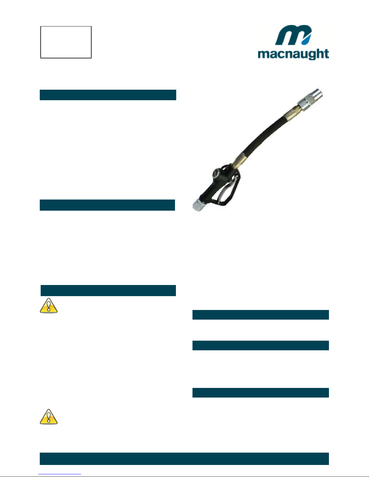
Thank you for purchasing a Macnaught HG100
dispensing gun complete with flexible extension and
non-drip nozzle. The Macnaught oil dispensing gun
and meter has been designed for use with engine oil,
gear oil, automatic transmission fluid, anti-freeze/antiboil and compatible fluids.
Macnaught also manufacture a complete range of
ratio oil pumps and retractable oil hose reels,
greasing equipment and accessories, to fulfil all your
fluid handling or greasing requirements.
Please read and retain this instruction manual to
assist you in the operation and maintenance of this
quality product.
GENERAL INFORMATION
This manual assists you in operating and maintaining your
new oil control gun. The information contained will help
you ensure many years of dependable performance and
trouble free operation.
Please take a few moments to read through this manual
before installing and operating your new oil control gun. If
you experience problems with this product, refer to the
trouble shooting sections of this manual. If you require
further assistance please contact your local Macnaught
distributor or authorised Macnaught service centre.
IMPORTANT INFORMATION
Your safety is important to us. Please read and follow
all safety instructions listed inside.
Some of these instructions alert you to the potential
for personal injury. “Cautions” listed throughout this
manual advise of potential practices or procedures
which may cause damage to your equipment.
Ensure all operators have access to adequate
instructions about safe operating and maintenance
procedures.
Do not exceed the maximum working pressure of
10500 kpa / 1500 psi / 105 bar.
Do not hit the oil control gun if it fails to operate. Refer
to “trouble shooting guide” or return the unit to your
nearest authorised service centre.
Never point the nozzle at yourself or anyone else.
Never exceed the pressure rating of any component.
installed in the System.
Before every use check all hoses for signs of wear,
leaks or loose fittings. Tighten all fluid connections
regularly and replace weak or damaged hoses.
Before attempting any repairs or maintenance of this
product firstly disconnect the air supply from the oil
pump, then release the oil line pressure by squeezing
the lever on your oil control gun.
ASSEMBLY
Use Teflon tape (or suitable thread sealant) when
connecting the oil control gun to an oil hose.
MANUAL NOZZLE OPERATION
With the nozzle pointing away from you turn the nozzle tip
clock-wise to open.
With the nozzle pointing away from you turn the nozzle tip
anti-clockwise to close.
HANDLE OPERATION
Ensure the manual nozzle is open before operating the
handle.
To latch the handle, squeeze the lever, push the latch
button on the rear of the gun and then release lever.
To release the latch in simply squeeze and release lever.
Introduction
READ THIS INFORMATION
CAREFULLY BEFORE USE.
CAUTION
Include s m odels
HG100-01
HG100-01-11
HG100-02
HG100B-01
HG624 Issue 8 © 2017 2
Before carrying out any maintenance, disconnect the
air supply to the pump and release the fluid pressure
in the system by pressing the lever on the control gun.
Inspect your metered oil control gun daily for any signs of
damage. Replace any damaged parts or components as
required.
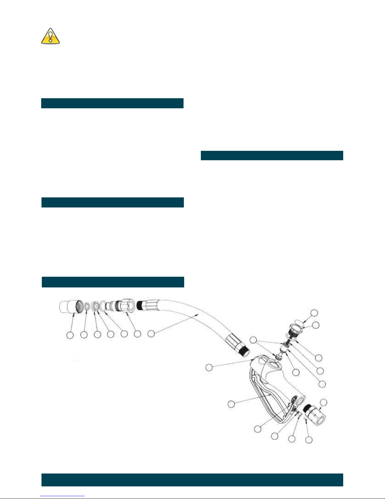
CONTROL HANDLE DISASSEMBLY
Use a clean bench to carry out maintenance.
A) Remove the oil delivery hose from the control gun inlet
swivel (14).
C) Carefully unscrew the valve cap (20), remove the valve
spring (19) and valve stem assembly (15,16,17) from
the gun body (8).
D) Remove the Gun Handle (9).
CONTROL HANDLE REASSEMBLY
A) Clean and inspect all parts for wear or damage.
Replace any suspect, worn or damaged components.
Note: Lightly lubricate all o-rings and seals before
assembly.
B) If required, carefully place new o-rings (16,17,18) onto
valve stem (15).
Note: o-ring (16) has a green dot and is different to the 2 o
-rings (17).
C) Re-fit the gun handle (9).
D) Carefully insert the valve stem assembly(15,16.17)
into the gun body (8).
E) Replace the valve spring (19), then replace the valve
cap.
Note: Ensure the valve spring locates around the nipple on
the underside of the valve cap.
F) Replace the swivel assembly (14).
Note: After assembly ensure the control gun handle
operating correctly.
MANUAL NOZZLE MAINTENANCE
1) Using a spanner and strap wrench, unscrew the nozzle
cap (1) from the nozzle body (6).
Note: All the nozzle seals must be replaced if the nozzle
is disassembled.
2) Remove all the old seals from the nozzle body (6).
3) Inspect the nozzle cap (1) and nozzle body (6) for
damage. Replace if found to be damaged.
4) Replace all the nozzle seals (2,3,4,5).
5) Lightly lubricate the seals, then reassemble nozzle.
B) Unscrew and remove swivel (14) from the control gun
inlet.
2 3
1
4
6 5
7
8
9
10
11
12
13
14
15
16
17
18
19
20
21
PARTS DIAGRAM

HG624 Issue 8 © 2017 3
SPARE PARTS LIST
TROUBLE SHOOTING GUIDE
Order for replacement
Item No. off Part / Set Kit ref Description
HG100-1K (KIT A) Overhaul Kit
1 1 Nozzle cap
2 1 A Quad Ring
3 1 A O'ring (BS212)
4 1 HG424s A Back up washer
5 1 A O'ring (BS214)
6 1 Nozzle body
7 1 Outlet hose
8 1 n/a - new gun required Gun body
9 1 HG411s Gun handle
10 1 A Latch pin
11 1 A Latch spring
12 1 A Latch cap
13 1 A Latch screw
14 1 HG421s Swivel (BSP)
14 1 HG422s Swivel (NPT)
15 2 A O'ring (BS113)
16 1 A O'ring (Green Dot)
17 1 order HG413s Valve stem
18 1 A Valve spring
19 1 A O'ring (BS122)
20 1 HG413s incl items 17, 18,21 Valve cap
21 1 Label
TROUBLE CAUSE REMEDY
Constant oil leak from the nozzle Damaged o'ring (16,17) Replace damaged o'ring
Intermittent drip from the nozzle Nozzle open or damaged 1) Remove the nozzle and blow out any dirt particles.
2) Close nozzle fully or replace the nozzle seals.
Oil leak from valve stem area Damaged o’rings (16,17 or 18) Replace damaged o’rings
Oil leaking from the sw ivel inlet Damaged sw ivel Replace sw ivel

HG624 Issue 8 © 2017 4
SPECIFICATIONS
For Warranty Terms and Conditions see macnaught.com.au
For a list of Australian Service Centres see macnaught.com.au
Flow Range: Up to 56 ltr / min (15 US GAL)
Maximum Pressure: 105 BAR / 10500 kPa / 1500 PSI
Maximum Operating Temp: 70 deg C (158 deg F)
Weight: 1.8 KG
Swivel Inlet: 3/4" BSPT or 3/4" NPT
Outlet: 3/4" NPT
Wetted Parts: Aluminium, Mild Steel, Nitrile Rubber
Fluid Compatibility: Transmission Fluid, Anti-freeze / Anti-Boil, Engine oil
Diesel Oil, and Lubricating oils to SAE140
Note:
This product should be disposed of according to all applicable local
and national government environment regulations and guidelines.
 Loading...