

Macnaught ER-RMP, ER-M, ER-RMA, GA012P, GB012P Operation Manual

FLOWRATE INDICATOR / TOTALIZER
Electronic Register (ER)
METER MOUNT REMOTE MOUNT
ER-RMA
ER-M ER-RMP
GA012P GB012P
Signal input flowmeter: NPN and Reed
MS574
0210
0007

MS574 0210 0007
Page 2
SAFETY INSTRUCTIONS
Any responsibility is lapsed if the instructions and procedures as described in this
manual are not followed.
LIFE SUPPORT APPLICATIONS: The ER is not designed for use in life support
appliances, devices, or systems where malfunction of the product can reasonably be
expected to result in a personal injury. Customers using or selling these products for use
in such applications do so at their own risk and agree to fully indemnify the manufacturer
and supplier for any damages resulting from such improper use or sale.
Electro static discharge does inflict irreparable damage to electronics! Before installing
or opening the unit, the installer has to discharge himself by touching a well-grounded
object.
This unit must be installed in accordance with the EMC guidelines (Electro Magnetic
Compatibility).
DISPOSAL - WEEE DIRECTIVE
The WEEE Directive requires the recycling of waste electrical and electronic equipment
in the European Union.
Whilst the WEEE Directive does not apply to some of Macnaught’s products, we
support its policy and ask you to be aware of how to dispose of this product.
The crossed out wheelie bin symbol illustrated and found on our products signifies that
this product should not be disposed of in general waste or landfill.
Please contact your local dealer national distributor or Macnaught Technical Services
for information on product disposal..
SAFETY RULES AND PRECAUTIONARY MEASURES
The manufacturer accepts no responsibility whatsoever if the following safety rules and
precautions instructions and the procedures as described in this manual are not followed.
Modifications of the ER implemented without preceding written consent from the manufacturer,
will result in the immediate termination of product liability and warranty period.
Installation, use, maintenance and servicing of this equipment must be carried out by authorized
technicians.
Check the mains voltage and information on the manufacturer's plate before installing the unit.
Check all connections, settings and technical specifications of the various peripheral devices
with the ER supplied.
Open the casing only if all leads are free of potential.
Never touch the electronic components (ESD sensitivity).
Never expose the system to heavier conditions than allowed according to the casing
classification (see manufacture's plate and chapter 4.2.).
If the operator detects errors or dangers, or disagrees with the safety precautions taken, then
inform the owner or principal responsible.
The local labor and safety laws and regulations must be adhered to.
MS574 0210 0007
Page 3
ABOUT THE OPERATION MANUAL
This operation manual is divided into two main sections:
The daily use of the unit is described in chapter 2 "Operation". These instructions are meant for
users.
The following chapters and appendices are exclusively meant for electricians/technicians. These
provide a detailed description of all software settings and hardware installation guidance.
This operation manual describes the standard unit as well as most of the options available. For
additional information, please contact your supplier.
A hazardous situation may occur if the ER is not used for the purpose it was designed for or
is used incorrectly. Please carefully note the information in this operating manual indicated
by the pictograms:
A "warning" indicates actions or procedures which, if not performed correctly, may lead to
personal injury, a safety hazard or damage of the ER or connected instruments.
A "caution" indicates actions or procedures which, if not performed correctly, may lead to
personal injury or incorrect functioning of the ER or connected instruments.
A "note" indicates actions or procedures which, if not performed correctly, may indirectly
affect operation or may lead to an instrument response which is not planned.
Hardware version : FB03.03.xx
Software version : MCN0121
Manual : MS574 0210 0007
© Copyright 2013 : Macnaught – All rights reserved
Information in this manual is subject to change without prior notice. The
manufacturer is not responsible for mistakes in this material or for incidental
damage caused as a direct or indirect result of the delivery, performance or
use of this material.
© All rights reserved. No parts of this publication may be reproduced or used
in any form or by any means without written permission of your supplier.

MS574 0210 0007
Page 4
CONTENTS MANUAL
Safety instructions ................................................................................................................................... 2
Disposal - WEEE Directive ...................................................................................................................... 2
Safety rules and precautionary measures ............................................................................................... 2
About the operation manual .................................................................................................................... 3
Contents manual ...................................................................................................................................... 4
1. Introduction ......................................................................................................................................... 5
1.1. System description of the ER ......................................................................................... 5
2. Operational ......................................................................................................................................... 6
2.1. General .......................................................................................................................... 6
2.2. Control panel .................................................................................................................. 6
2.3. Operator information and functions ............................................................................... 7
3. Configuration ...................................................................................................................................... 8
3.1. Introduction .................................................................................................................... 8
3.2. Programming SETUP-level ............................................................................................ 8
3.2.1. General .......................................................................................................................... 8
3.2.2. Overview functions SETUP level ................................................................................. 11
3.2.3. Explanation of SETUP-functions.................................................................................. 12
1 - Total ................................................................................................................... 12
2 - Flowrate ............................................................................................................. 13
3 - Display ............................................................................................................... 14
4 - Power management .......................................................................................... 14
5 - Flowmeter .......................................................................................................... 15
6 - Others ................................................................................................................ 15
4. Installation ........................................................................................................................................ 16
4.1. General directions ........................................................................................................ 16
4.2. Installation / surrounding conditions ............................................................................ 16
4.3. Dimensions- Enclosure ................................................................................................ 17
4.4. Installing the hardware ................................................................................................. 19
4.4.1. Introduction .................................................................................................................. 19
4.4.2. Terminal connectors with power supply ....................................................................... 19
5. Maintenance ..................................................................................................................................... 22
5.1. General directions ........................................................................................................ 22
5.2. Repair ........................................................................................................................... 22
Appendix A: Technical specification ................................................................................................... 23
Appendix B: Problem solving .............................................................................................................. 25
Index of this manual ............................................................................................................................... 26
List of figures in this manual .................................................................................................................. 27
List of configuration settings ................................................................................................................. 28
MS574 0210 0007
Page 5
1. INTRODUCTION
1.1. SYSTEM DESCRIPTION OF THE ER
Functions and features
The flowrate / totalizer model ER is a microprocessor driven instrument designed to display flowrate,
total and accumulated total.
This product has been designed with a focus on:
ultra-low power consumption to allow long-life battery powered applications (type PB / PC),
several mounting possibilities with Meter mount, GRP or aluminum enclosures for industrial
surroundings,
ability to process two types of flowmeter signals, NPN and Reed.
Flowmeter input
This manual describes the unit with a pulse type input from the flowmeter "-P version".
One flowmeter with a NPN or Reed switch output can be connected to the ER. To power the sensor,
several options are available.
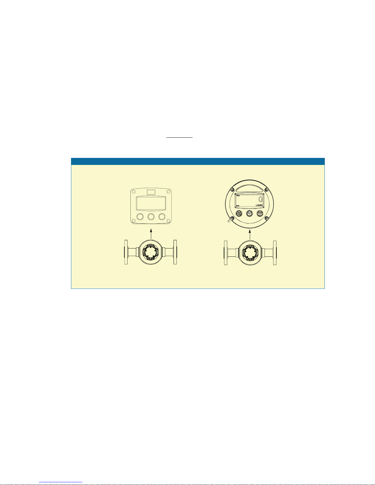
Overview typical application ER
Fig. 1: Typical application for the ER
Configuration of the unit
The ER has been designed to be implemented in many types of applications. For that reason, a
SETUP-level is available to configure your ER according to your specific requirements.
It includes several important features, such as K-factors, measurement units, signal selection etc. All
setting are stored in EEPROM memory and will not be lost in the event of power failure. To extend
the battery-life time, please use of the power-management functions as described in chapter 3.2.3.
Display information
The unit has a large transflective LCD with all kinds of symbols and digits to display measuring units,
status information, trend-indication and key-word messages.
Flowrate and totals can be displayed either with the small 8mm digits or with the 17mm digits.
A backup of the total and accumulated total in EEPROM memory is made every minute.
Options
The following options are available: power- and sensor-supply options, panel-mount, wall-mount,
meter mount and weather-proof enclosures and LED backlight.
MS574 0210 0007
Page 6
2. OPERATIONAL
2.1. GENERAL
The ER may only be operated by personnel who are authorized and trained by the
operator of the facility. All instructions in this manual are to be observed.
Take careful notice of the " Safety rules, instructions and precautionary measures " in
the front of this manual.
This chapter describes the daily use of the ER. This instruction is meant for users / operators.
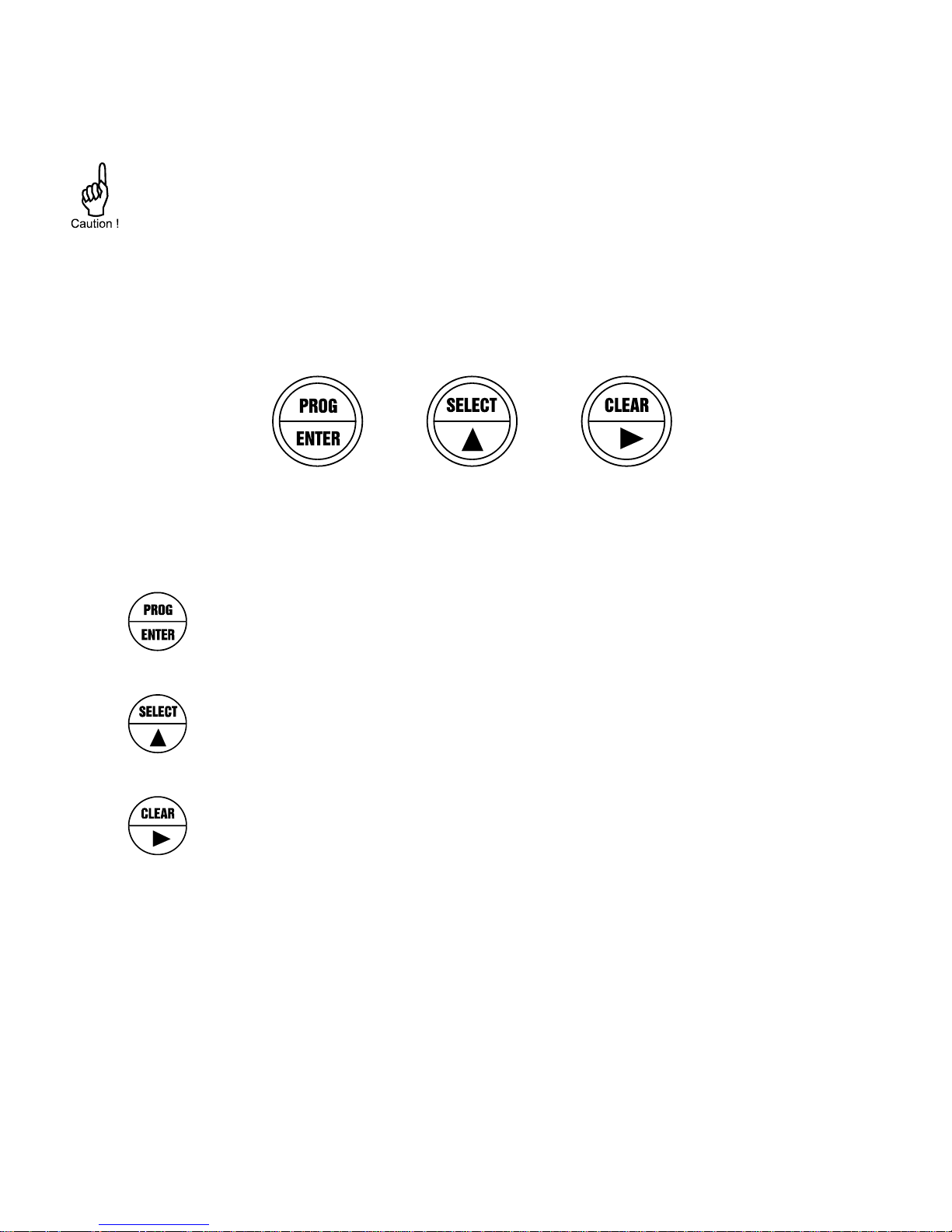
2.2. CONTROL PANEL
The following keys are available:
Fig. 2: Control Panel.
Functions of the keys
This key is used to program and save new values or settings.
It is also used to gain access to SETUP-level; please read chapter 3.
This key is used to SELECT accumulated total.
The arrow-key is used to increase a value after PROG has been pressed
or to configure the unit; please read chapter 3.
Press this key twice to CLEAR the value for total.
The arrow-key is used to select a digit after PROG has been pressed or to
configure the unit; please read chapter 3.
MS574 0210 0007
Page 7
2.3. OPERATOR INFORMATION AND FUNCTIONS
In general, the ER will always function at Operator level. The information displayed is dependent
upon the SETUP-settings The signal from the connected sensor is processed by the ER in the
background, whichever screen refresh rate setting is chosen. After pressing a key, the display will be
updated very quickly during a 30 second period, after which it will slow-down again.
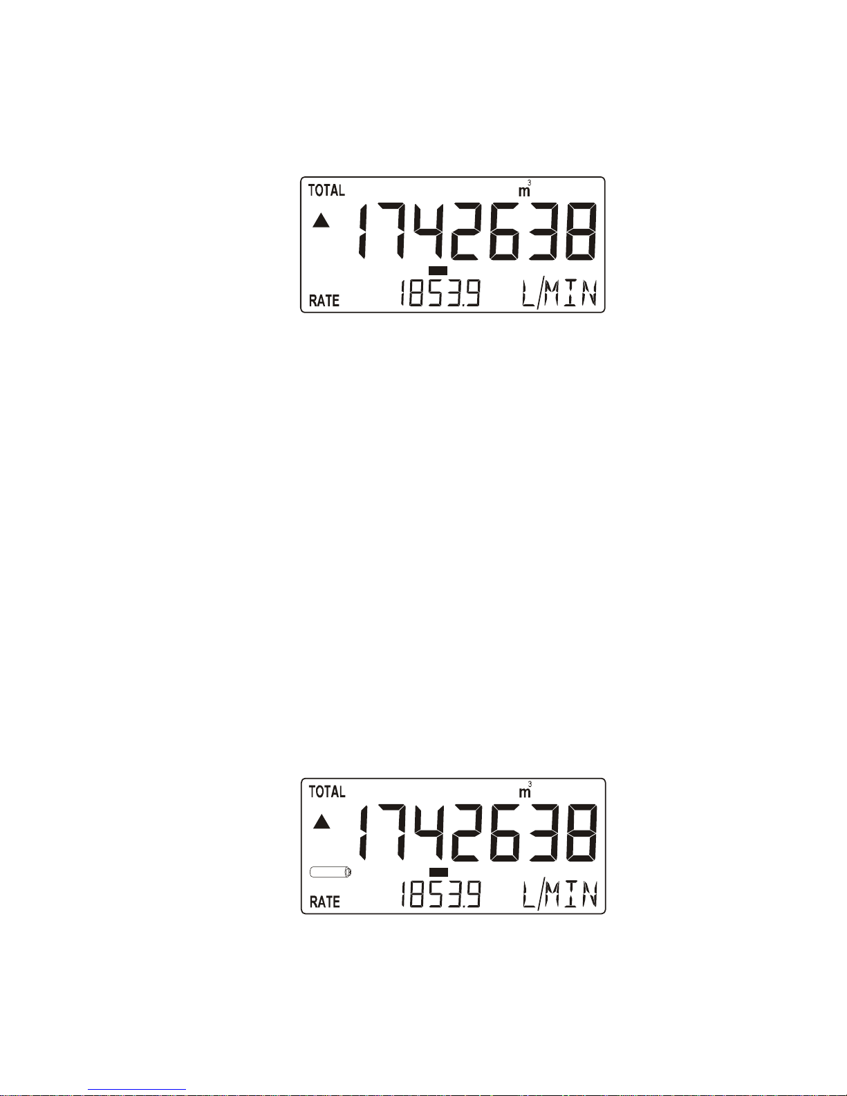
Fig. 3: Example of display information during process.
For the Operator, the following functions are available:
Display flowrate / total or flowrate
This is the main display information of the ER. After selecting any other information, it will
always return to this main display automatically.
Total is displayed on the upper-line of the display and flowrate on the bottom line.
It is possible to display flowrate only with the large 17mm digits; in this instance press the
SELECT-key to read the total.
When "-------" is shown, then the flowrate value is too high to be displayed. The arrows
indicate the increase/decrease of the flowrate trend.
Clear total
The value for total can be re-initialized. To do so, press CLEAR twice. After pressing CLEAR
once, the flashing text "PUSH CLEAR" is displayed. To avoid re-initialization at this stage,
press another key than CLEAR or wait for 20 seconds.
Re-initialization of total DOES NOT influence the accumulated total.
Display accumulated total
When the SELECT-key is pressed, total and accumulated total are displayed. The
accumulated total cannot be re-initialized. The value will count up to 99,999,999,999. The unit
and number of decimals are displayed according to the configuration settings for total.
Low-battery alarm
When the battery voltage drops, it must be replaced. At first "low-battery" will flash, but as
soon as it is displayed continuously, the battery MUST be replaced shortly after!
Only original batteries supplied by the manufacturer may be used, else the guarantee and
liability will be terminated. The remaining lifetime after the first moment of indication is
generally several days up to some weeks.
Fig. 4: Example of low-battery alarm.
Alarm 01-03
When "alarm" is displayed, please consult Appendix B: problem solving.
RUN
LOW BATTERY
RUN
MS574 0210 0007
Page 8
3. CONFIGURATION
3.1. INTRODUCTION
This and the following chapters are exclusively meant for electricians and non-operators. In these,
an extensive description of all software settings and hardware connections are provided.
Mounting, electrical installation, start-up and maintenance of the instrument may only
be carried out by trained personnel authorized by the operator of the facility. Personnel
must read and understand this Operating Manual before carrying out its instructions.
The ER may only be operated by personnel who are authorized and trained by the
operator of the facility. All instructions in this manual are to be observed.
Ensure that the measuring system is correctly wired up according to the wiring
diagrams. The housing may only be opened by trained personnel.
Take careful notice of the " Safety rules, instructions and precautionary measures " in
the front of this manual.
3.2. PROGRAMMING SETUP-LEVEL
3.2.1. GENERAL
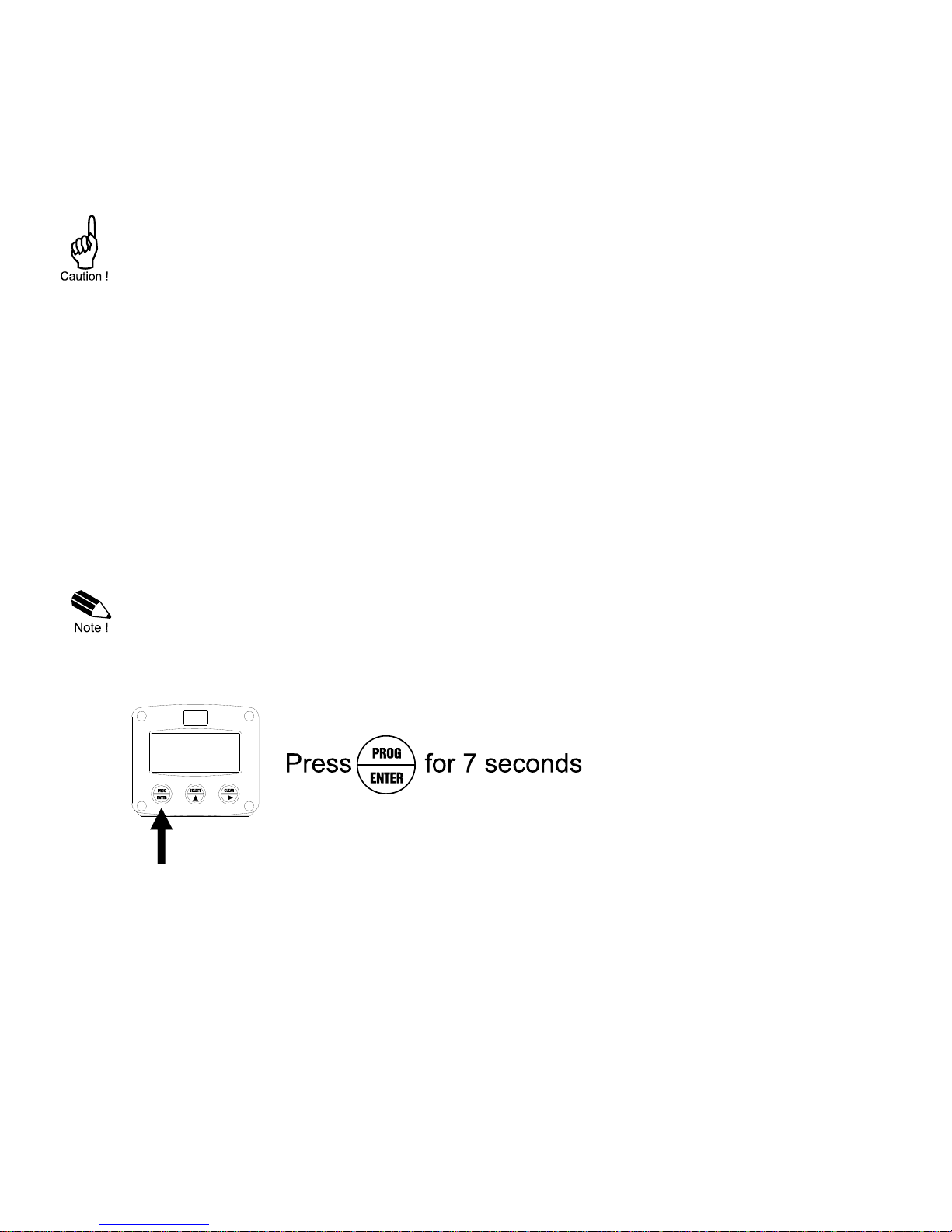
Configuration of the ER is done at SETUP-level. SETUP-level is reached by pressing the
PROG/ENTER key for 7 seconds; at which time, both arrows will be displayed. In order to return
to the operator level, PROG will have to be pressed for three seconds. Alternatively, if no keys are
pressed for 2 minutes, the unit will exit SETUP automatically.
SETUP can be reached at all times while the ER remains fully operational.
Note: A pass code may be required to enter SETUP. Without this pass code access to SETUP is
denied.
To enter SETUP-level:
MS574 0210 0007
Page 9
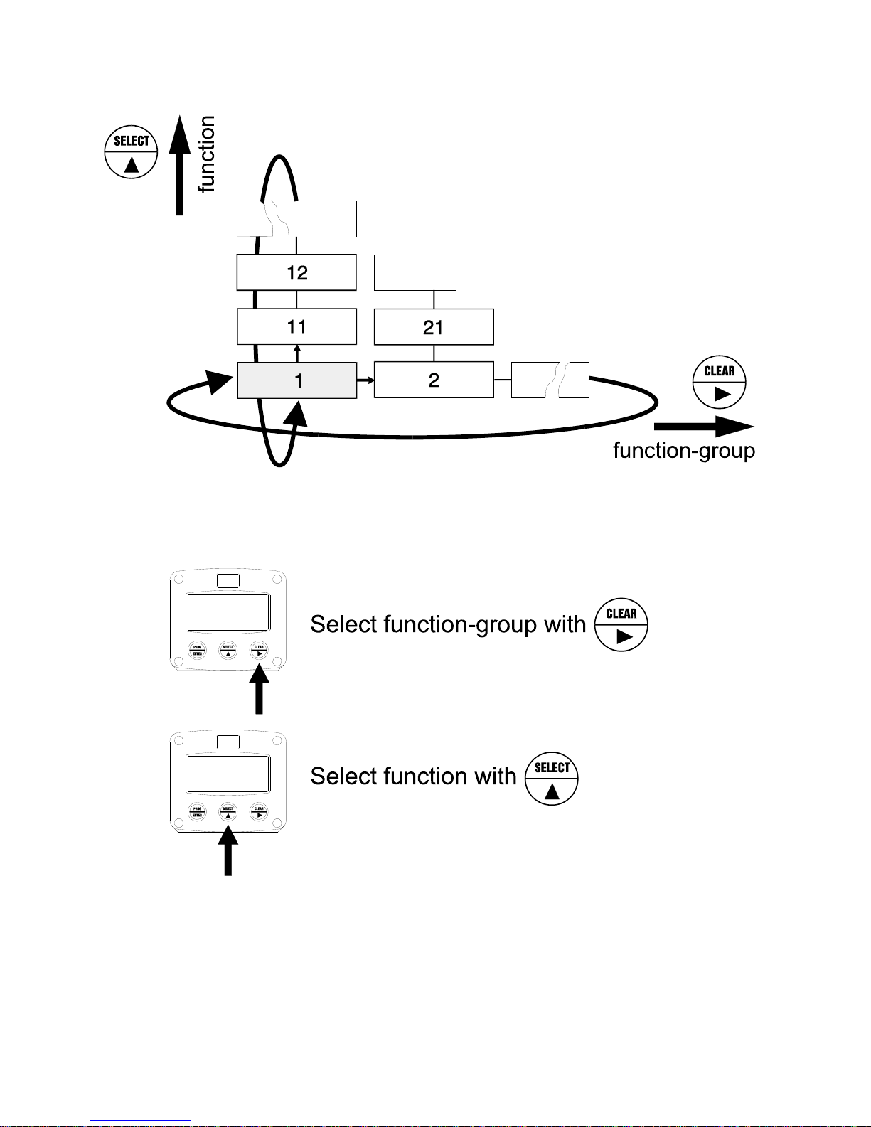
Matrix structure SETUP-level:
SCROLLING THROUGH SETUP-LEVEL
Selection of function-group and function:
SETUP is divided into several function groups and functions.
Each function has a unique number, which is displayed below the word "SETUP" at the bottom of
the display. The number is a combination of two figures. The first figure indicates the function-group
and the second figure the sub-function. Additionally, each function is expressed with a keyword.
After selecting a sub-function, the next main function is selected by scrolling through all "active" subfunctions (e.g. 1, 11, 12, 13, 14, 1, 2, 3, 31 etc.). The “CLEAR” button can be used
to jump a step back if you missed the desired function.
 Loading...