

0001
MS1208
0809
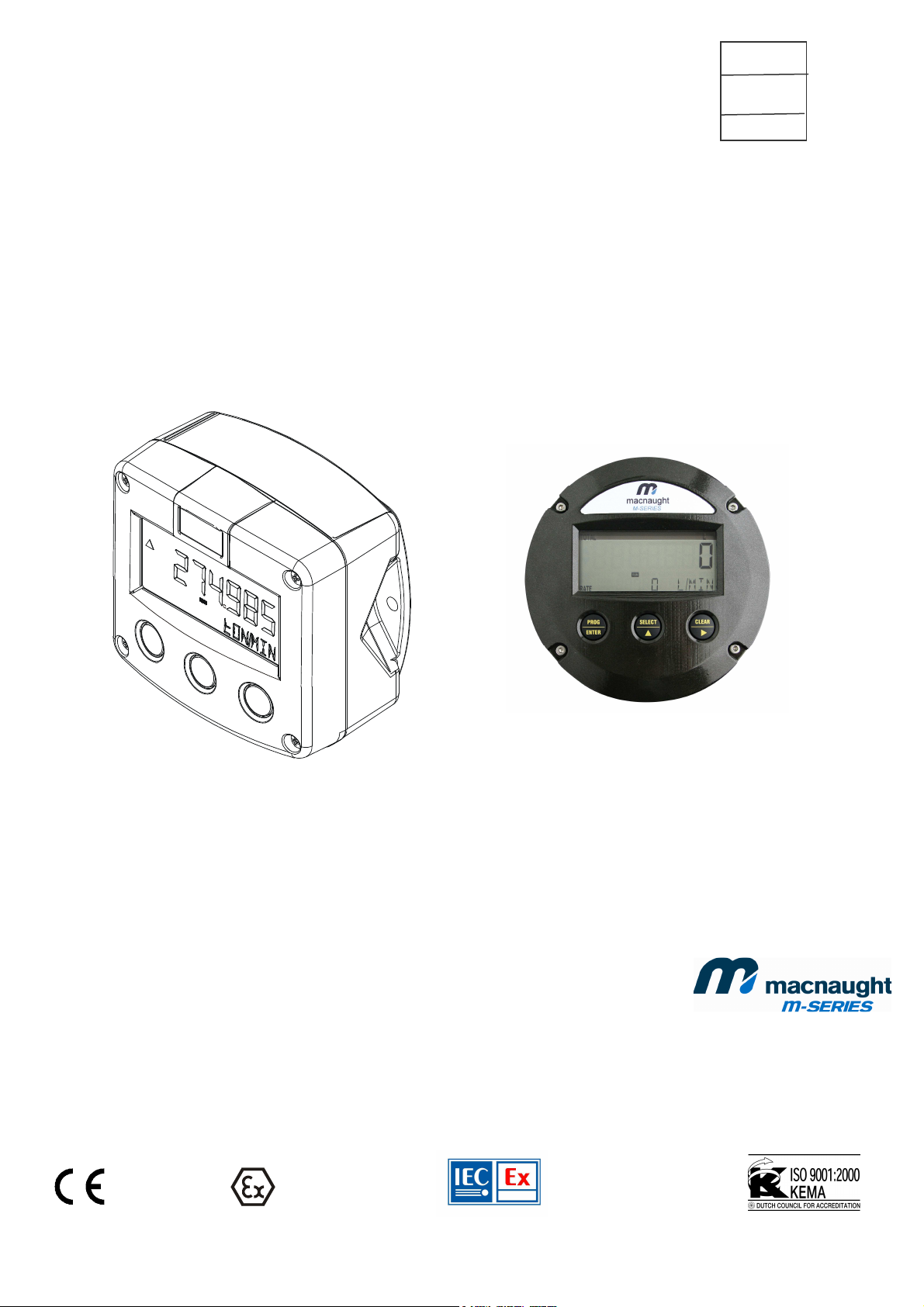
FLOWRATE INDICATOR / TOTALIZER
Intrinsically Safe
H5012PHR
H5012PHE - H5012PHA
Signal input flowmeter: pulse, Namur and coil.

Page
2
SAFETY INSTRUCTIONS
Any responsibility is lapsed if the instructions and procedures as described in this
manual are not followed.
LIFE SUPPORT APPLICATIONS: The H5012-P is not designed for use in life support
appliances, devices, or systems where malfunction of the product can reasonably be
expected to result in a personal injury. Customers using or selling these products for
use in such applications do so at their own risk and agree to fully indemnify the
manufacturer and supplier for any damages resulting from such improper use or sale.
Electro static discharge does inflict irreparable damage to electronics! Before installing
or opening the unit, the installer has to discharge himself by touching a well-grounded
object.
This unit must be installed in accordance with the EMC guidelines (Electro Magnetic
Compatibility).
Do connect a proper grounding to the aluminum casing as indicated if the H5012-P has
been supplied with the 115-230V AC power-supply type PM. The green / yellow wire
between the back-casing and removable terminal-block may never be removed.
Intrinsically Safe applications: follow the instructions as mentioned in Chapter 5.
SAFETY RULES AND PRECAUTIONARY MEASURES
The manufacturer accepts no responsibility whatsoever if the following safety rules and
precautions instructions and the procedures as described in this manual are not followed.
Modifications of the H5012-P implemented without preceding written consent from the
manufacturer, will result in the immediate termination of product liability and warranty period.
Installation, use, maintenance and servicing of this equipment must be carried out by authorized
technicians.
Check the mains voltage and information on the manufacturer's plate before installing the unit.
Check all connections, settings and technical specifications of the various peripheral devices
with the H5012-P supplied.
Open the casing only if all leads are free of potential.
Never touch the electronic components (ESD sensitivity).
Never expose the system to heavier conditions than allowed according to the casing
classification (see manufacture's plate and chapter 4.2.).
If the operator detects errors or dangers, or disagrees with the safety precautions taken, then
inform the owner or principal responsible.
The local labor and safety laws and regulations must be adhered to.
MS1208 0809 0001(H5012).doc
Page
3
ABOUT THE OPERATION MANUAL
This operation manual is divided into two main sections:
The daily use of the unit is described in chapter 2 "Operation". These instructions are meant for
users.
The following chapters and appendices are exclusively meant for electricians/technicians. These
provide a detailed description of all software settings and hardware installation guidance.
This operation manual describes the standard unit as well as most of the options available. For
additional information, please contact your supplier.
A hazardous situation may occur if the H5012-P is not used for the purpose it was designed
for or is used incorrectly. Please carefully note the information in this operating manual
indicated by the pictograms:
A "warning" indicates actions or procedures which, if not performed correctly, may lead to
personal injury, a safety hazard or damage of the H5012-P or connected instruments.
A "caution" indicates actions or procedures which, if not performed correctly, may lead to
personal injury or incorrect functioning of the H5012-P or connected instruments.
A "note" indicates actions or procedures which, if not performed correctly, may indirectly
affect operation or may lead to an instrument response which is not planned.
Hardware version : FB03.03.xx
Software version : 03.02.xx
Manual : MS1208 0809 0001(H5012).doc
© Copyright 2009 : Macnaught
Information in this manual is subject to change without prior notice. The
manufacturer is not responsible for mistakes in this material or for incidental
damage caused as a direct or indirect result of the delivery, performance or
use of this material.
© All rights reserved. No parts of this publication may be reproduced or used
in any form or by any means without written permission of your supplier.
MS1208 0809 0001(H5012).doc

Page
4
CONTENTS MANUAL
safety instructions............................................................................................................................................2
Safety rules and precautionary measures.......................................................................................................2
About the operation manual ............................................................................................................................3
Contents manual..............................................................................................................................................4
1.
1.1.
2.
2.1.
2.2.
2.3.
3.
3.1.
3.2.
3.2.1.
3.2.2.
3.2.3.
4.
4.1.
4.2.
4.3.
4.4.
4.4.1.
4.4.2.
5.
5.1.
5.2.
5.3.
5.4.
6.
6.1.
6.2.
Appendix A: Technical specification..............................................................................................................13
Appendix B: Problem solving.........................................................................................................................13
Index of this manual.......................................................................................................................................13
List of figures in this manual ..........................................................................................................................13
Notes ..................................................................................................................................................13
Notes ..................................................................................................................................................13
List of configuration settings .........................................................................................................................13
Introduction..................................................................................................................................5
System description of the H5012-P .......................................................................................5
Operational..................................................................................................................................6
General ..................................................................................................................................6
Control panel..........................................................................................................................6
Operator information and functions........................................................................................7
Configuration...............................................................................................................................8
Introduction ............................................................................................................................8
Programming SETUP-level....................................................................................................8
General ..................................................................................................................................8
Overview functions SETUP level .........................................................................................11
Explanation of SETUP-functions..........................................................................................12
1 - Total...........................................................................................................................12
2 - Flowrate.....................................................................................................................13
3 - Display.......................................................................................................................13
4 - Power management...................................................................................................13
5 - Flowmeter..................................................................................................................13
6 - Others........................................................................................................................13
Installation.................................................................................................................................13
General directions................................................................................................................13
Installation / surrounding conditions.....................................................................................13
Dimensions- Enclosures ......................................................................................................13
Installing the hardware.........................................................................................................13
Introduction ..........................................................................................................................13
Terminal connectors with power supply - type : PB / PD / PX.............................................13
Intrinsically safe applications.....................................................................................................13
General information and instructions:..................................................................................13
Terminal connectors Intrinsically Safe applications:............................................................13
Configuration examples Intrinsically Safe applications:.......................................................13
Battery replacement instructions..........................................................................................13
Maintenance..............................................................................................................................13
General directions................................................................................................................13
Repair...................................................................................................................................13
MS1208 0809 0001(H5012).doc
Page
5
1. INTRODUCTION
1.1. SYSTEM DESCRIPTION OF THE H5012-P
Functions and features
The flowrate / totalizer model H5012-P is a microprocessor driven instrument designed to display
flowrate, total and accumulated total.
This product has been designed with a focus on:
ultra-low power consumption to allow long-life battery powered applications (type PB / PC),
intrinsic safety for use in hazardous applications (type XI),
several mounting possibilities with GRP or aluminum enclosures for industrial surroundings,
ability to process all types of flowmeter signals,
Flowmeter input
This manual describes the unit with a pulse type input from the flowmeter "-P version". Other
versions are available to process (0)4-20mA or 0-10V flowmeter signals.
One flowmeter with a passive or active pulse, Namur or coil signal output can be connected to the
H5012-P. To power the sensor, several options are available.
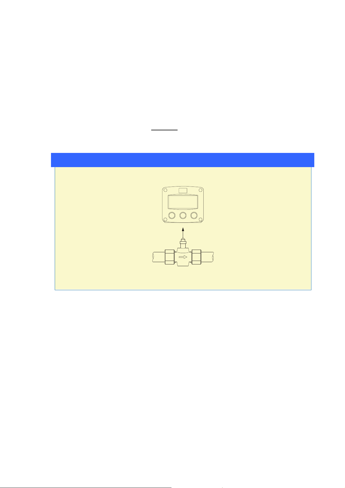
Overview Typical applications H5012
Overview typical application F012
Fig. 1: Typical application for the H5012-P.
Configuration of the unit
The H5012-P has been designed to be implemented in many types of applications. For that reason,
a SETUP-level is available to configure your H5012-P according to your specific requirements.
It includes several important features, such as K-factors, measurement units, signal selection etc. All
setting are stored in EEPROM memory and will not be lost in the event of power failure. To extend
the battery-life time, please use of the power-management functions as described in chapter 3.2.3.
Display information
The unit has a large transflective LCD with all kinds of symbols and digits to display measuring units,
status information, trend-indication and key-word messages.
Flowrate and totals can be displayed either with the small 8mm digits or with the 17mm digits.
A backup of the total and accumulated total in EEPROM memory is made every minute.
Options
The following options are available: intrinsic safety, power- and sensor-supply options, panel-mount,
wall-mount and weather-proof enclosures, flame proof enclosure and LED backlight.
MS1208 0809 0001(H5012).doc
Page
6
2. OPERATIONAL
2.1. GENERAL
The H5012-P may only be operated by personnel who are authorized and trained by the
operator of the facility. All instructions in this manual are to be observed.
Take careful notice of the " Safety rules, instructions and precautionary measures " in
the front of this manual.
This chapter describes the daily use of the H5012-P. This instruction is meant for users / operators.
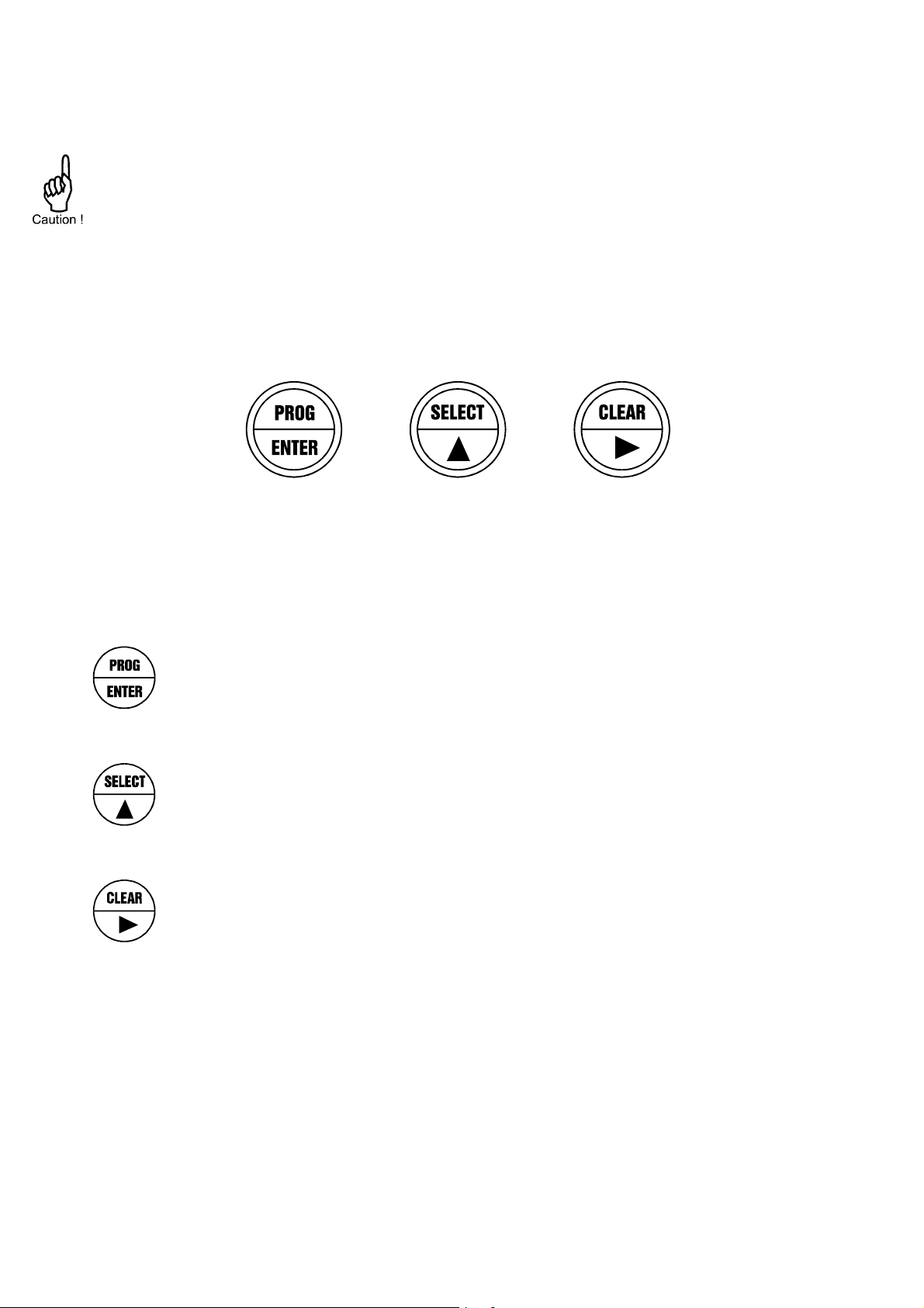
2.2. CONTROL PANEL
The following keys are available:
Fig. 2: Control Panel.
Functions of the keys
This key is used to program and save new values or settings.
Press this key twice to CLEAR the value for total.
configure the unit; please read chapter 3.
It is also used to gain access to SETUP-level; please read chapter 3.
This key is used to SELECT accumulated total.
The arrow-key t is used to increase a value after PROG has been pressed
or to configure the unit; please read chapter 3.
The arrow-key 4is used to select a digit after PROG has been pressed or to
MS1208 0809 0001(H5012).doc

Page
7
2.3. OPERATOR INFORMATION AND FUNCTIONS
In general, the H5012-P will always function at Operator level. The information displayed is
dependant upon the SETUP-settings The signal from the connected sensor is processed by the
H5012-P in the background, whichever screen refresh rate setting is chosen. After pressing a key,
the display will be updated very quickly during a 30 second period, after which it will slow-down
again.
RUN
Fig. 3: Example of display information during process.
For the Operator, the following functions are available:
Display flowrate / total or flowrate
This is the main display information of the H5012-P. After selecting any other information, it
will always return to this main display automatically.
Total is displayed on the upper-line of the display and flowrate on the bottom line.
It is possible to display flowrate only with the large 17mm digits; in this instance press the
SELECT-key to read the total.
When "-------" is shown, then the flowrate value is too high to be displayed. The arrows v
indicate the increase/decrease of the flowrate trend.
Clear total
The value for total can be re-initialized. To do so, press CLEAR twice. After pressing CLEAR
once, the flashing text "PUSH CLEAR" is displayed. To avoid re-initialization at this stage,
press another key than CLEAR or wait for 20 seconds.
Re-initialization of total DOES NOT influence the accumulated total.
Display accumulated total
When the SELECT-key is pressed, total and accumulated total are displayed. The
accumulated total cannot be re-initialized. The value will count up to 99,999,999,999. The unit
and number of decimals are displayed according to the configuration settings for total.
Low-battery alarm
When the battery voltage drops, it must be replaced. At first "low-battery" will flash, but as
soon as it is displayed continuously, the battery MUST be replaced shortly after!
Only original batteries supplied by the manufacturer may be used, else the guarantee and
liability will be terminated. The remaining lifetime after the first moment of indication is
generally several days up to some weeks.
LOW BATTERY
RUN
Fig. 4: Example of low-battery alarm.
MS1208 0809 0001(H5012).doc
Page
8
Alarm 01-03 When "alarm" is displayed, please consult Appendix B: problem solving.
3. CONFIGURATION
3.1. INTRODUCTION
This and the following chapters are exclusively meant for electricians and non-operators. In these,
an extensive description of all software settings and hardware connections are provided.
Mounting, electrical installation, start-up and maintenance of the instrument may only
be carried out by trained personnel authorized by the operator of the facility. Personnel
must read and understand this Operating Manual before carrying out its instructions.
The H5012-P may only be operated by personnel who are authorized and trained by the
operator of the facility. All instructions in this manual are to be observed.
Ensure that the measuring system is correctly wired up according to the wiring
diagrams. The housing may only be opened by trained personnel.
Take careful notice of the " Safety rules, instructions and precautionary measures " in
the front of this manual.
3.2. PROGRAMMING SETUP-LEVEL
3.2.1. GENERAL
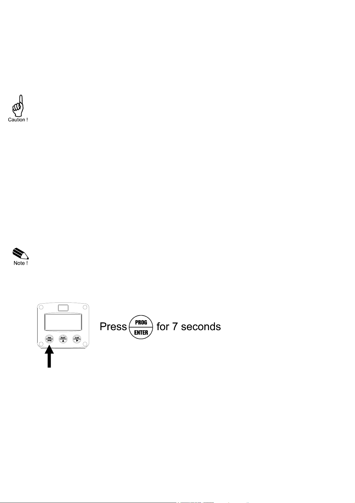
Configuration of the H5012-P is done at SETUP-level. SETUP-level is reached by pressing the
PROG/ENTER key for 7 seconds; at which time, both arrows v will be displayed. In order to return
to the operator level, PROG will have to be pressed for three seconds. Alternatively, if no keys are
pressed for 2 minutes, the unit will exit SETUP automatically.
SETUP can be reached at all times while the H5012-P remains fully operational.
Note: A pass code may be required to enter SETUP. Without this pass code access to SETUP is
denied.
To enter SETUP-level:
MS1208 0809 0001(H5012).doc
Page
9
Matrix structure SETUP-level:
SCROLLING THROUGH SETUP-LEVEL
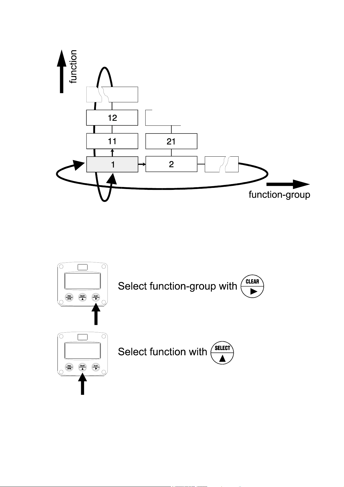
Selection of function-group and function:
SETUP is divided into several function groups and functions.
Each function has a unique number, which is displayed below the word "SETUP" at the bottom of
the display. The number is a combination of two figures. The first figure indicates the function-group
and the second figure the sub-function. Additionally, each function is expressed with a keyword.
After selecting a sub-function, the next main function is selected by scrolling through all "active" subfunctions (e.g. 1t, 11t, 12t, 13t, 14t, 14, 24, 3t, 31 etc.). The “CLEAR” button can be used
to jump a step back if you missed the desired function.
MS1208 0809 0001(H5012).doc
Page
10
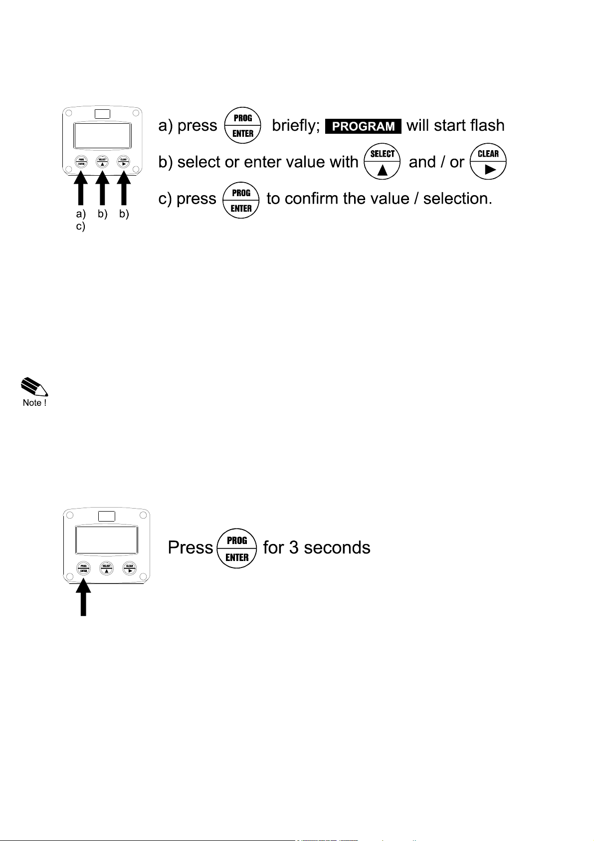
To change or select a value:
To change a value, use 4 to select the digits and t to increase that value.
If the new value is invalid, the increase signt or decrease-signu will be displayed while you are
programming.
To select a setting, tis used to select in one direction and 4 can be used to select in the other
direction.
When data is altered but ENTER is not pressed, then the alteration can still be cancelled by waiting
for 20 seconds or by pressing ENTER for three seconds: the PROG-procedure will be left
automatically and the former value reinstated.
Note: alterations will only be set after ENTER has been pressed!
To return to OPERATOR-level:
In order to return to the operator level, PROG will have to be pressed for three seconds. Also, when
no keys are pressed for 2 minutes, SETUP will be left automatically.
MS1208 0809 0001(H5012).doc

Page
11
3.2.2. OVERVIEW FUNCTIONS SETUP LEVEL
SETUP FUNCTIONS AND VARIABLES
1 TOTAL
11 UNIT L - m3 - kg - lb - GAL - USGAL - bbl - no unit
12 DECIMALS 0 - 1 - 2 - 3 (Ref: displayed value)
13 K-FACTOR: 0.000010 - 9,999,999
14 DECIMALS K-FACTOR 0 - 6
2 FLOWRATE
21
22 TIME UNIT
23 DECIMALS
24 K-FACTOR
25 DECIMALS K-FACTOR
26 CALCULATION
27 CUT-OFF
3 DISPLAY
31 FUNCTION total - flowrate
32 BACKLIGHT (optional) off - green - amber
33 BL. BRIGHTNESS 1 - 5
4 POWER MANAGEMENT
41 LCD UPDATE fast - 1 sec - 3 sec - 15 sec - 30 sec - off
42 BATTERY MODE operational - shelf
5 FLOWMETER
51 SIGNAL npn - npn_lp - reed - reed_lp - pnp - pnp_lp - namur - coil_hi -
6 OTHERS
61 TYPE / MODEL H5012-P
62 SOFTWARE VERSION 03.xx.xx
63 SERIAL NO. xxxxxxx
64 PASS CODE 0000 - 9999
65 TAGNUMBER 0000000 - 9999999
UNIT mL - L - m3 - mg - g - kg - ton - GAL - bbl - lb - cf - REV -
no unit - scf - Nm3 - NL - P
sec - min - hour - day
0 - 1 - 2 - 3 (Ref: displayed value)
0.000010 - 9,999,999
0 - 6
per 1 - 255 pulses
0.1 - 999.9 seconds
coil_lo - active
MS1208 0809 0001(H5012).doc

Page
12
3.2.3. EXPLANATION OF SETUP-FUNCTIONS
1 - TOTAL
MEASUREMENT UNIT
11
DECIMALS
12
K-FACTOR
13
DECIMALS K-FACTOR
14
SETUP - 11 determines the measurement unit for total and accumulated
total. The following units can be selected:
L - m3 - kg - lb. - GAL - USGAL - bbl - _ (no unit).
Alteration of the measurement unit will have consequences for operator
and SETUP-level values.
Please note that the K-factor has to be adapted as well; the calculation is
not done automatically.
The decimal point determines for total and accumulated total the number
of digits following the decimal point. The following can be selected:
0000000 - 111111.1 - 22222.22 - 3333.333
With the K-factor, the flowmeter pulse signals are converted to a quantity.
The K-factor is based on the number of pulses generated by the
flowmeter per selected measurement unit (SETUP 11), for example per
cubic meter. The more accurate the K-factor, the more accurate the
functioning of the system will be.
Example 1: Calculating the K-factor.
Let us assume that the flowmeter generates 2.4813 pulses per
liter and the selected unit is "cubic meters / m3". A cubic meter
consists of 1000 parts of one liter which implies 2,481.3 pulses
per m3. So, the K-factor is 2,481.3. Enter for SETUP - 13:
"2481300" and for SETUP - 14 - decimals K-factor "3".
Example 2: Calculating the K-factor.
Let us assume that the flowmeter generates 6.5231 pulses per
gallon and the selected measurement unit is gallons. So, the KFactor is 6.5231. Enter for SETUP - 13: "6523100" and for
SETUP - 14 decimals K-factor "6".
This setting determines the number of decimals for the K-factor entered.
(SETUP 13). The following can be selected:
0 - 1 - 2 - 3 - 4 - 5 - 6
Please note that this setting influences the accuracy of the K-factor
indirectly. (i.e. the position of the decimal point and thus the value given)
This setting has NO influence on the displayed number of digits for total
(SETUP 12)!
MS1208 0809 0001(H5012).doc

Page
13
2 - FLOWRATE
The settings for total and flowrate are entirely separate. In this way, different units of measurement
can be used for each e.g. cubic meters for total and liters for flowrate.
The display update time for flowrate is one second or more.
MEASUREMENT UNIT
21
TIME UNIT
22
DECIMALS
23
K-FACTOR
24
DECIMALS K-FACTOR
25
CALCULATION
26
CUT-OFF TIME
27
SETUP - 21 determines the measurement unit for flowrate.
The following units can be selected:
mL - L - m3 - mg - g - kg - ton - GAL - bbl - lb - cf - REV -
no unit - scf - Nm3 - NL - P.
Alteration of the measurement unit will have consequences for operator
and SETUP-level values.
Please note that the K-factor has to be adapted as well; the calculation is
not done automatically.
The flowrate can be calculated per second (SEC), minute (MIN), hour
(HR) or day (DAY).
This setting determines for flowrate the number of digits following the
decimal point. The following can be selected:
00000 - 1111.1 - 2222.22 - 3333.333
With the K-factor, the flowmeter pulse signals are converted to a flowrate.
The K-factor is based on the number of pulses generated by the
flowmeter per selected measurement unit (SETUP 21), for example per
liter. The more accurate the K-factor, the more accurate the functioning of
the system will be. For examples read SETUP 13.
This setting determines the number of decimals for the K-factor
(SETUP 24). The following can be selected:
0 - 1 - 2 - 3 - 4 - 5 - 6
Please note that this SETUP - influences the accuracy of the K-factor
indirectly.
This setting has NO influence on the displayed number of digits for
"flowrate" (SETUP 23)!
The flowrate is calculated by measuring the time between a number of
pulses, for example 10 pulses. The more pulses the more accurate the
flowrate will be. The maximum value is 255 pulses.
Note: the lower the number of pulses, the higher the power consumption
of the unit will be (important for battery powered applications).
Note: for low frequency applications (below 10Hz): do not program more
than 10 pulses else the update time will be very slow.
Note: for high frequency application (above 1kHz) do program a value of
100 or more pulses.
With this setting, you determine a minimum flow requirement thresh-hold,
if during this time less than XXX-pulses (SETUP 26) are generated, the
flowrate will be displayed as zero.
The cut-off time has to be entered in seconds - maximum time is 999
seconds (about 15 minutes).
MS1208 0809 0001(H5012).doc

Page
14
3 - DISPLAY
FUNCTION
31
The functions below will only effect the optional LED-backlight.
BACKLIGHT
(OPTION)
32
BRIGHTNESS
(OPTION)
33
The large 17mm digits can be set to display total or flowrate.
When "total" is selected, both total and flowrate are displayed
simultaneously.
When "flowrate" is selected, only flowrate will be displayed with it’s
measuring unit while total will be displayed after pressing SELECT.
If a LED backlight has been supplied, the color can be selected.
Following selections are available:
OFF - GREEN - AMBER
The density of the backlight can be set in following range:
1 - 5
One is minimum and five is maximum brightness.
4 - POWER MANAGEMENT
When used with the internal battery option, the user can expect reliable measurement over a long
period of time. The H5012-P has several smart power management functions to extend the battery
life time significantly. Two of these functions can be set:
LCD NEW
41
BATTERY-MODE
42
The calculation of the display-information influences the power
consumption significantly. When the application does not require a fast
display update, it is strongly advised to select a slow refresh rate.
Please understand that NO information will be lost; every pulse will be
counted and the output signal will be generated in the normal way.
The following can be selected:
Fast - 1 sec - 3 sec - 15 sec - 30 sec - off.
Example battery life-time:
life-time with a coil pick-up, 1kHz. pulses and FAST update: about 2 years.
life-time with a coil pick-up, 1kHz. pulses and 1 sec update: about 5 years.
Note: after a button has been pressed by the operator - the display
refresh rate will always switch to FAST for 30 seconds. When "OFF" is
selected, the display will be switched off after 30 seconds and will be
switched on as soon as a button has been pressed.
The unit has two modes: operational or shelf.
After "shelf" has been selected, the unit can be stored for several years; it
will not process the sensor signal; the display is switched off but all
settings and totals are stored. In this mode, power consumption is
extremely low.
To wake up the unit again, press the SELECT-key twice.
MS1208 0809 0001(H5012).doc

Page
15
SIGNAL
51
TYPE OF SIGNAL
5 - FLOWMETER
The H5012-P is able to handle several types of input signal. The type of
flowmeter pickup / signal is selected with SETUP 51.
Read also par. 4.4.2. or 4.4.3 - flowmeter input terminals.
NPN NPN input
NPN - LP
REED Reed-switch input
REED - LP
PNP PNP input
PNP - LP
NAMUR Namur input
COIL HI High sensitive coil input -
COIL LO Low sensitive coil input -
ACTIVE
EXPLANATION
NPN input
with low pass filter
Reed-switch input
with low pass filter
PNP input
with low pass filter
Active pulse input
detection level 1.2V DC
RESISTANCE
100kOhm
pull-up
100kOhm
pull-up
1mOhm
pull-up
1mOhm
pull-up
47kOhm
pull-down
100kOhm
pull-down
820 Ohm
pull-down
47kOhm 10KHz.
FREQ. / M
V
6 kHz. (open collector)
1.2 kHz.
600 Hz.
120 Hz. Less sensitive
6 kHz.
1.2 kHz. Less sensitive
4 kHz.
20mV
p.t.p.
90mV
p.t.p.
Normal sensitivity
REMARK
(open collector)
less sensitive
External power
required
Sensitive for
disturbance!
External power
required
TYPE OF MODEL
61
VERSION SOFTWARE
62
SERIAL NUMBER
63
PASS CODE
64
TAGNUMBER
65
6 - OTHERS
For support and maintenance it is important to have information about the
characteristics of the H5012-P.
Your supplier will ask for this information in the case of a serious
breakdown or to assess the suitability of your model for upgrade
considerations.
For support and maintenance it is important to have information about the
characteristics of the H5012-P.
Your supplier will ask for this information in the case of a serious
breakdown or to assess the suitability of your model for upgrade
considerations.
For support and maintenance it is important to have information about the
characteristics of the H5012-P.
Your supplier will ask for this information in the case of a serious
breakdown or to assess the suitability of your model for upgrade
considerations.
All SETUP-values can be pass code protected.
This protection is disabled with value 0000 (zero).
Up to and including 4 digits can be programmed, for example 1234.
For identification of the unit and communication purposes, a unique tag
number of maximum 7 digits can be entered.
MS1208 0809 0001(H5012).doc

Page
16
4. INSTALLATION
4.1. GENERAL DIRECTIONS
Mounting, electrical installation, start-up and maintenance of this instrument may only
be carried out by trained personnel authorized by the operator of the facility. Personnel
must read and understand this Operating Manual before carrying out its instructions.
The H5012-P may only be operated by personnel who are authorized and trained by the
operator of the facility. All instructions in this manual are to be observed.
Ensure that the measuring system is correctly wired up according to the wiring
diagrams. Protection against accidental contact is no longer assured when the housing
cover is removed or the panel cabinet has been opened (danger from electrical shock).
The housing may only be opened by trained personnel.
Take careful notice of the " Safety rules, instructions and precautionary measures " at
the front of this manual.
4.2. INSTALLATION / SURROUNDING CONDITIONS
Take the relevant IP classification of the casing into account (see manufactures plate). Even an IP67
(NEMA 4X) casing should NEVER be exposed to strongly varying (weather) conditions.
When panel-mounted, the unit is IP65 (NEMA 4X)!
When used in very cold surroundings or varying climatic conditions, take the necessary precautions
against moisture by placing a dry sachet of silica gel, for example, inside the instrument case.
Mount the H5012-P on a solid structure to avoid vibrations.
MS1208 0809 0001(H5012).doc

Page
17
4.3. DIMENSIONS- ENCLOSURES
75 mm (2.95")
115 mm (4.53”)
31 mm
HE
2
2
,
5
m
m
30mm
30mm
D=16mm
D=20mm
D=16mm
120 mm (4.72")
130 mm (5.12")
30mm 30mm
60 mm (2.36")
112 mm (4.40")
HA
HB/HC
PG9
(1.22”)
22,5mm
PG9
M20 x 1,5
29.1 mm (1.15”)
98 mm (3.86”)
Fig. 5: HA / HE and panel mount Housings
Fig. 6 : HR Housing
MS1208 0809 0001(H5012).doc

Page
18
4.4. INSTALLING THE HARDWARE
4.4.1. INTRODUCTION
Electro static discharge does inflict irreparable damage to electronics! Before installing
or opening the unit, the installer has to discharge himself by touching a well-grounded
object.
This unit must be installed in accordance with the EMC guidelines (Electro Magnetic
Compatibility).
Do ground the aluminum casing properly as indicated, if the H5012-P has been supplied
with the 115-230V AC power-supply type PM. The green / yellow wire between the backcasing and removable terminal-block may never be removed.
Fig. 7: Grounding aluminum enclosure with option PM 115-230V AC.
FOR INSTALLATION, PAY EMPHATIC ATTENTION TO:
Separate cable glands with effective IP67 (NEMA4X) seals for all wires.
Unused cable entries: ensure that you fit IP67 (NEMA4X) plugs to maintain rating.
A reliable ground connection for both the sensor, and if applicable, for the metal casing. (above)
An effective screened cable for the input signal, and grounding of it’s screen to the “┴ “ terminal
or at the sensor itself, whichever is appropriate to the application.
MS1208 0809 0001(H5012).doc

Page
19
5
POWER SUPPLY
TYPE: PD / PX
SENSOR SIGNAL
SIGNAL
3
+++
10
POWER SUPPLY
+
SENSOR
4.4.2. TERMINAL CONNECTORS WITH POWER SUPPLY - TYPE : PB / PD / PX
For Intrinsically Safe applications: read chapter 5.
The following terminal connectors are available:
PULSE INPUT
TYPE: P
Fig. 8: Overview of terminal connectors H5012-P-(PB / PD / PX) and options.
SENSOR SUPPLY
Type PB / PD / PX - terminal 3: sensor supply 1.2V, 3.2V:
Terminal 3 provides a limited supply voltage of 3.2 V DC (coil signals 1.2V) for the signal output of
the flowmeter.
Note: This voltage MAY NOT be used to power the flowmeters electronics, converters etc, as it will
not provide adequate sustained power ! All energy used by the flowmeters pick-up will directly
influence the battery life-time (type PB). It is strongly advised to use a "zero power" pickup such as a
coil or reed-switch when operating without external power. It is possible to use some low power NPN
or PNP output signals, but the battery life time will be significantly reduced (consult your distributor).
Type PD - terminal 6: sensor supply 8.2V:
With this option, a basic but real sensor supply of max. 5mA@8.2V is available to power e.g. a
Namur sensor.
UNIT
4 9
SUPPLY
TYPE: PD
61 2
BACKLIGHT
OPTION: ZB
MS1208 0809 0001(H5012).doc

Page
20
3
2
1
GND
Input
sensitivity
selectable:
coil high / low
shielding
2
1
GND
shielding
REMARKS: TERMINAL CONNECTORS:
Terminals 1-3; Flowmeter input:
Three basic types of flowmeter signals can be connected to the unit: pulse, active pulse or coil. The
screen of the signal wire must be connected to the common ground terminal
The input signal type has to be selected with the correct SETUP-function (read par. 3.2.3.)
Coil-signal:
The H5012-P is suitable for use with flowmeters which have a coil output signal.
Two sensitivity levels can be selected with the SETUP-function:
COIL LO: sensitivity from about 90mVp-p.
COIL HI: sensitivity from about 20mVp-p.
Type ZF (option): offers for setting COIL HI : sensitivity from about 10mVp-p.
Type ZG (option): offers for setting COIL HI : sensitivity from about 5mVp-p.
Coil signal input
INTERNAL EXTERNAL
V ref.
1.2V DC
COIL
+
Common ground unit
COIL
Pulse-signal NPN / NPN-LP:
The H5012-P is suitable for use with flowmeters which have a NPN output signal. For reliable pulse
detection, the pulse amplitude has to go below 1.2V. Signal setting NPN-LP employs a low-pass
signal noise filter, which limits the maximum input frequency - read par. 3.2.3.
NPN signal input
INTERNAL EXTERNAL
+ 3.2V DC
100K
low-pass filter
selection NPN-LP
SIGNAL
NPN
Common ground unit
MS1208 0809 0001(H5012).doc

Page
21
Active signal input
2
1
GND
shielding
1
GND
shielding
+3.2V DC
6
Option Type PD-PF-PM: 8.1V DC
Pulse-signal PNP / PNP-LP:
The H5012-P is suitable for use with flowmeters which have a PNP output signal. Terminal 3 offers
3.2V which has to be switched by the sensor to terminal 2 (SIGNAL). For a reliable pulse detection,
the pulse amplitude has to go above 1.2V. Signal setting PNP-LP employs a low-pass signal noise
filter, which limits the maximum input frequency - read par. 3.2.3.
A sensor supply voltage of 8.1V DC can be provided with option PD on terminal 6.
PNP signal input
INTERNAL EXTERNAL
3
PNP
SIGNAL
low-pass filter
selection PNP-LP
100K
2
Common ground unit
Active signal:
Active signal selection may well be desired in the case of option PD being supplied for sensor
supply.
INTERNAL EXTERNAL
+8.1V DC (type PD)
6
SIGNAL
Resistance value:
see signal selection
Common ground unit
MS1208 0809 0001(H5012).doc

Page
22
2
1
GND
shielding
820 Ohm
+8.1V DC
2
1
GND
shielding
Reed-switch:
The H5012-P is suitable for use with flowmeters which have a reed-switch. To avoid pulse bounce
from the reed-switch, it is advised to select REED LP - low-pass filter (read par. 3.2.3.)
Reed - switch signal input
INTERNAL EXTERNAL
+ 3.2V DC
1M
low-pass filter
selection REED-LP
Common ground unit
NAMUR-signal:
The H5012-P is suitable for flowmeters with an Namur signal. The standard H5012-P is not able to
power the Namur sensor, as an external power supply for the sensor is required. However, a 8.2V
sensor supply voltage (terminal 6) can be provided with type PD.
SIGNAL
REED
SWITCH
Namur signal input
INTERNAL EXTERNAL
(Type PD: +8.1V)
6
SIGNAL
Namur
Common ground unit
Terminal 4-5: POWER SUPPLY UNIT - TYPE PD / PX:
To power the unit an internal battery can be used (type PB) and / or an external DC power supply
of 8-30V DC (type PX) or 16-30V DC (type PD).
Connect the "-" to terminal 4 and the "+" to terminal 5. When power is applied to these terminals, the
optional internal battery will be disabled / enabled automatically to extend the battery life time.
Terminal 6: Power supply type PD: 8.2V sensor supply.
With this option, a limited power supply for the sensor is available, for example to power a Namur
sensor. It offers 8.2V DC (max. 5mA).
Remark: this terminal is only available if option PD has been ordered.
Terminal 9-10: power supply backlight - type ZB (option):
To power the backlight, a voltage in the range 20-30V DC has to be connected.
Maximum current 30mA. Connect the "-" to terminal 9 and the "+" to terminal 10.
MS1208 0809 0001(H5012).doc

Page
23
5. INTRINSICALLY SAFE APPLICATIONS
5.1. GENERAL INFORMATION AND INSTRUCTIONS:
Mounting, electrical installation, start-up and maintenance of this device may only be
carried out by trained personnel authorized by the operator of the facility. Personnel
must read and understand this Operating Manual before carrying out its instructions.
This device may only be operated by personnel who are authorized and trained by the
operator of the facility. All instructions in this manual are to be observed.
Ensure that the measuring system is correctly wired up according to the wiring
diagrams. Protection against accidental contact is no longer assured when the housing
cover is removed or the cabinet has been opened (danger of electric shock). The
housing may only be opened by trained personnel.
Take careful notice of the " Safety rules, instructions and precautionary measures " in
the front of this manual.
Safety Instructions
For installation under ATEX directive: this intrinsically safe device must be installed in
accordance with the ATEX directive 94/9/EC and the product certificate KEMA
09ATEX0019 X
For installation under IECEx scheme: this intrinsically safe device must be installed in
accordance with the product certificate IECEx KEM 09.0004X
Exchange of Intrinsically Safe battery MAC-LiBAT with certificate number KEMA
09ATEX0017 U or IECEx KEM 09.0003U - is allowed in Hazardous Area.
See paragraph 5.4 for battery replacement instructions.
Please note
Special conditions for safe use mentioned in both the certificate and the installation
instructions must be observed for the connection of power to both input and / or output
circuits.
When installing this device in hazardous areas, the wiring and installation must comply
with the appropriate installation standards for your industry.
Study the following pages with wiring diagrams per classification.
Serial number and year of production
This information can be looked-up on the display:
setup function (par. 3.2.2.).
Fig. 9: Example serial number.
MS1208 0809 0001(H5012).doc

Page
24
5
POWER SUPPLY
TYPE: PD / PX
SENSOR SIGNAL
SIGNAL
3
+++
10
POWER SUPPLY
+
SENSOR
Label information pulse input type - P (inside and outside the enclosure)
Fig. 10: Label information Intrinsically Safe application.
5.2. TERMINAL CONNECTORS INTRINSICALLY SAFE APPLICATIONS:
Terminal connectors H5012-P-(PC / PD / PX)-XI-(ZB):
PULSE INPUT
TYPE: P
Fig. 11: Overview terminal connectors XI - Intrinsically Safe applications.
Remarks power supply options:
Type PC: offers - additional to type PX - an internal Intrinsically Safe lithium battery. This ATEX &
IECEx certified battery (MAC-LiBAT MS493XS) may be changed in hazardous area.
Type PD: offers with terminal 6 - additional to type PX - a real sensor supply of 8.2V DC to power a
Namur sensor for example.
Type PX: as standard, all intrinsically product are supplied with terminal 4 and 5 to power the
product externally.
UNIT
SUPPLY
TYPE: PD
4 9
MS1208 0809 0001(H5012).doc
61 2
BACKLIGHT
OPTION: ZB

Page
25
I.S. flowmeter
Configuration example IIA - IIB and IIC
Backlight option: type ZB
(not used in this example).
Signal
Supply *
Supply backlight
+
-
Note: above values are safety values.
Consult the technical specification for operational values.
Configuration example IIA
–
IIB & IIC
Configuration example IIA
–
IIB & IIC application H5012
-P-PD-XI-ZB
5.3. CONFIGURATION EXAMPLES INTRINSICALLY SAFE APPLICATIONS:
Configuration example no. 1
H5012-P-PC-(PX)-XI- (ZB) Battery Powered
TERMINAL C ONNECTORS
F0-series
Common ground
Main supply
Common ground
type of signal
Circuit depends on
Common ground
*Sensor supply voltage for pulse flowmeter type P : Terminal 3: 1.2 - 3.2V DC.
Please note: type PX may be used in combination with the battery (type PC).
PX will power the unit; the battery will be disabled automatically till power is disconnected.
9 10
4 5
1 2 3
battery powered unitF012-P-PC-(PX)-XI-(ZB) -
HAZARDOUS AREA SAFE AREA
Basic power supply type PX:
8-30V DC
(not used in this example).
input type: P
pulse
Fig. 12: Configuration example Intrinsically Safe.
Configuration example no. 2
Configuration example IIA - IIB and IIC application - F012-P-PD-XI-ZB
TERMINAL CON NECTORS
F0-series
Supply *
l
a
n
g
Supply *
i
s
f
o
e
p
y
t
Signal
0
1
9
6
5
4
3
2
1
Backlight option: type ZB
Power supply type PD: 16-30V DC
I.S. flowmeter
input type: P
pulse
Supply backlight
Common ground
Main supply
Common ground
n
o
s
d
n
e
p
e
d
t
i
u
c
r
i
C
Common ground
*Sensor supply voltage for pulse type P: Terminal 3: 1.2V - 3.2V DC. Terminal 6: 8.2V DC.
Please note: type PD may be used in combination with the battery (type PC). PD will power the unit; the battery will be disabled automatically till power is disconnected.
Fig. 13: Configuration example Intrinsically Safe.
HAZARDOUS AREA SAFE AREA
= max. 30 V
Uo
= max. 200 mA
Io
= max. 0,75 W
Po
+
= max. 30 V
Uo
= max. 200 mA
Io
-
= max. 1,2 W
Po
Power supply
For example
MTL5025
Power supply
For example
MTL5025
MS1208 0809 0001(H5012).doc

Page
26
Note: above values are safety values.
Consult the technical specification for operational values.
+
-
Note: above values are safety values.
Consult the technical specification for operational values.
Uo
Io
Po
Configuration example IIA
–
IIB & IIC application H5012
-P-PX-XI-ZB
Configuration example IIA
–
IIB & IIC application H5012
-P-PX-XI-ZB
Configuration example no. 3
Configuration example IIA - IIB and IIC application - F012-P-PX-XI-(ZB)
TERMINAL CONNECTORS
F0-series
Supply backlight
Common ground
Main supply
Common ground
Circuit depends on
Common ground
*Sensor supply voltage for pulse type P: Terminal 3: 1.2V - 3.2V DC.
Please note: type PX may be used in combination with the battery (type PC). PX will power the unit; the battery will be disabled automatically till power is disconnected.
Supply *
type of signal
10
9
5
4
3
Signal
1 2
Backlight option: type ZB
(not used in this example).
I.S. flowmeter
input type: P
pulse
Power supply type PX: 8-30V DC
HAZARDOU S AREA SAFE ARE A
+
= max. 30 V
Uo
= max. 200 mA
Io
-
= max. 1,2 W
Po
Fig. 14: Configuration example Intrinsically Safe.
Configuration example no. 4
Power supply
For example
MTL5025
Configuration example IIA - IIB and IIC application - F012-P-PX-XI-ZB
TERMINAL CONNECTORS
F0-series
Supply backlight
Common ground
Main supply
Common ground
type of signal
Circuit depends on
Common ground
*Sensor supply voltage for pulse type P: Terminal 3: 1.2V - 3.2V DC.
Please note: type PX may be used in combination with the battery (type PC). PX will power the unit; the battery will be disabled automatically till power is disconnected.
Supply *
Signal
10
9
5
4
3
1 2
Backlight option: type ZB
Power supply type PX: 8-30V DC
I.S. flowmeter
input type: P
pulse
Fig. 15: Configuration example Intrinsically Safe.
HAZARDOUS AREA SAFE AREA
= max. 30 V
Uo
= max. 200 mA
Io
= max. 0,75 W
Po
+
= max. 30 V
Uo
= max. 200 mA
Io
-
= max. 1,2 W
Po
+
= max. 30 V
= max. 150 mA
-
= max. 0,92 W
Power supply
For example
MTL5025
Power supply
For example
MTL5025
Power supply
For example
MTL5025
MS1208 0809 0001(H5012).doc

Page
27
MAC-LiBAT-001 - INST002
B
A
T
T
E
R
Y
H5-series
:
cnaught I.S. battery pack !
TEX0017 U
M 09.0003
U
ual for replacement instructions.
: Fire, explosion or severe
lt if mistreated. Do not
ssemble, incinerate, heat
°F) or expose contents to water
.
burns
recharge,
above
INSTRUCTION SHEET BATTERY REPLACEMENT MAC-LiBAT-001
5.4. BATTERY REPLACEMENT INSTRUCTIONS
Manufacturer
Macnaught PTY Ltd. - Australia
Fig. 16: Battery replacement instructions Intrinsically Safe Battery.
41-49 Henderson Street - Turrella NSW 2205
www.macnaught.com - sales@macnaught.com.au
Safety Instructions
WARNING: Fire, explosion or severe burns may result if
mistreated. Do not recharge, crush, disassemble, incinerate,
MS1208 0809 0001(H5012).doc
WARNING
heat above 100°C (212°F) or expose contents to wate r.
Battery label:
0344
Macnaught PTY Ltd Australia
Intrinsically Safe Battery
Part. no.: MAC-LiBAT-001
Uo = 3.9V Co = 100 F
Io = 35mA Lo = 25mH
Po = 35mW Ta = -40°C to +70°C
Primary Lithium Battery - Only replace with Ma
II 1 G Ex ia IIC
Ga Ex ia IIC
µ
KEMA 09A
IECEx KE
Consult man
WARNING
crush, disa
100°C (212
may resu
Replacement Instructions
Mounting, electrical installation, start-up and maintenance of
this device may only be carried out by trained personnel
authorized by the operator of the facility.
Personnel must read and understand this Instruction before
carrying out its instructions.
It is allowed to replace the Intrinsically Safe battery MAC-LiBAT-001
in hazardous area. The battery may only be replaced with an
original
For replacement,
MAC-LiBAT-001 manufactured by Macnaught PTY Ltd.
unplug the connector carefully and lift
the old
battery out of the mounting clip. The new battery can be placed in
the clip and the connector plugged on the board.
Disposal
Disposal should be done in accordance with applicable regulations,
which vary from country to country. Trashing of used batteries is
forbidden and disposal can be done through non-profit organizations
mandated by local authorities or organized by professionals.

Page
28
6. MAINTENANCE
6.1. GENERAL DIRECTIONS
Mounting, electrical installation, start-up and maintenance of the instrument may only
be carried out by trained personnel authorized by the operator of the facility. Personnel
must read and understand this Operating Manual before carrying out its instructions.
The H5012-P may only be operated by personnel who are authorized and trained by the
operator of the facility. All instructions in this manual are to be observed.
Ensure that the measuring system is correctly wired up according to the wiring
diagrams. Protection against accidental contact is no longer assured when the housing
cover is removed or the panel cabinet has been opened (danger from electrical shock).
The housing may only be opened by trained personnel.
Take careful notice of the " Safety rules, instructions and precautionary measures " in
the front of this manual.
The H5012-P does not require special maintenance unless it is used in low-temperature applications
or surroundings with high humidity (above 90% annual mean). It is the users responsibility to take all
precautions to dehumidify the internal atmosphere of the H5012-P in such a way that no
condensation will occur, for example by placing dry silica-gel sachet in the casing just before closing
it. Furthermore, it is required to replace or dry the silica gel periodically as advised by the silica gel
supplier.
Battery life-time:
It is influenced by several issues :
Type of sensor: read chapter 3.2.3. NPN and PNP inputs consume more energy than coil inputs.
Input frequency: the higher the frequency, the shorter the battery life-time.
Flowrate calculation: the lower number of pulses (SETUP 26) the shorter the battery life-time.
Display update: fast display update uses significantly more power.
Low temperatures; the available power will be less due to battery chemistry.
Note: It is strongly advised to use only necessary functions.
Check periodically:
The condition of the casing, cable glands and front panel.
The input/output wiring for reliability and aging symptoms.
The process accuracy. As a result of wear and tear, re-calibration of the flowmeter might be
necessary. Do not forget to re-enter any subsequent K-factor alterations.
The indication for low-battery.
Clean the casing with soapy-water. Do not use any aggressive solvents as these might damage
the coating.
6.2. REPAIR
This product cannot be repaired by the user and must be replaced with an equivalent certified
product. Repairs should only be carried out by the manufacturer or his authorized agent.
MS1208 0809 0001(H5012).doc

Page
29
APPENDIX A: TECHNICAL SPECIFICATION
GENERAL
Display
Type High intensity reflective numeric and alphanumeric LCD, UV-resistant.
Digits Seven 17mm (0.67") and eleven 8mm (0.31"). Various symbols and measuring units.
Refresh rate User definable: 8 times/sec - 30 secs.
Type ZB (option) Bi-color configurable LED-backlight - green or amber. Intensity adjustable from the keyboard.
Enclosures
General
Control Keys
Painting
Panel-mount enclosures
Classification
Panel cut-out
Type HC
Type HB
Field/wall-mount enclosures
Classification
Aluminum enclosure
Type HA
GRP enclosures
Type HE
Operating temperature
Operational -40°C to +80°C (-40°F to +178°F).
Intrinsically Safe -40°C to +70°C (-40°F to +158°F).
Power requirements
Type PC Intrinsically Safe lithium battery - life-time depends upon settings - up to 5 years.
Type PD 16-30 V DC. Power consumption max. 1 Watt.
Type PX 8-30 V DC (also available with PB / PC). Power consumption max. 0.3 Watt.
Type ZB
Note I.S. application for intrinsically safe applications, consult the safety values in the certificate.
Sensor excitation
Type PC / PX Sensor supply voltage: 3.2V DC for pulse signals and 1.2V DC for coil pick-up.
Type PD With pulse input type P: sensor supply 1.2, 3.2, 8.2V DC - max. 5mA@8.2V DC.
Terminal connections
Type: Removable plug-in terminal strip. Wire max. 1.5mm2 and 2.5mm2
Data protection
Type EEPROM backup of all settings. Data retention at least 10 years.
Pass code Configuration settings can be pass code protected.
Hazardous area
(option)
Intrinsically safe
Type XI
Die-cast aluminum or GRP (Glassfibre Reinforced Polyamide) enclosure with Polycarbonate
window, silicone and EPDM gaskets. UV stabilized and flame retardant material.
Three industrial micro-switch keys. UV-resistant silicone keypad.
Aluminum enclosure only: UV-resistant 2-component industrial painting.
Dimensions: 130 x 120 x 60mm (5.10" x 4.72" x 2.38") – LxHxD.
IP65 / NEMA 4X
115 x 98mm (4.53" x 3.86") LxH.
GRP panel-mount enclosure
Aluminum panel-mount enclosure
Dimensions: 130 x 120 x 75mm (5.10” x 4.72” x 2.95”) – LxHxD.
IP67 / NEMA 4X
Drilling: 2x PG9 – 1x M20.
Drilling: 2x 16mm (0.63”) – 1x 20mm (0.78”).
20-30V DC. Power consumption max. 1 Watt. Note: with type PF / PM: internally powered.
Please note: this is not a real sensor supply. Only suitable for sensors with a very low power
consumption like coils (sine wave) and reed-switches.
Analog sensors type A / U: sensor supply not available.
With analog input type A / U: as connected power supply voltage (internally linked)
ATEX & IECEx approval ref.: <EX> II 1 GD EEx ia IIC T4 T100°C
.
MS1208 0809 0001(H5012).doc

Page
30
Environment
Electromagnetic
Compliant ref: EN 61326 (1997), EN 61010-1 (1993)
compatibility
Low voltage directive Compliant ref: EN60950.
INPUTS
Flowmeter
Type P Coil/sine wave (minimum 20mVpp or 80mVpp - sensitivity selectable), NPN/PNP, open
collector, reed-switch, Namur, active pulse signals.
Frequency Minimum 0 Hz - maximum 7 kHz for flowrate.
Maximum frequency depends on signal type and internal low-pass filter.
E.g. Reed switch with low-pass filter: max. frequency 120 Hz.
K-Factor 0.000010 - 9,999,999 with variable decimal position.
Low-pass filter Available for all pulse signals.
Note For coil signal input: higher sensitivity is available - type ZF (10mVpp) / type ZG (5mVpp).
OPERATIONAL
Operator functions
Displayed functions
• total and/or flowrate.
• total and accumulated total.
• total can be reset to zero by pressing the CLEAR-key twice.
Total
Digits 7 digits.
Units L, m3, GAL, USGAL, KG, lb, bbl, no unit.
Decimals 0 - 1 - 2 or 3.
Note total can be reset to zero.
Accumulated total
Digits
11 digits.
Units / decimals according to selection for total.
Flowrate
Digits 7 digits.
Units mL, L, m3, Gallons, KG, Ton, lb, bl, cf, RND, ft3, scf, Nm3, Nl, igal - no units.
Decimals 0 - 1 - 2 or 3.
Time units /sec - /min - /hr - /day.
MS1208 0809 0001(H5012).doc

Page
31
APPENDIX B: PROBLEM SOLVING
In this appendix, several problems are included that can occur when the H5012-P is going to be
installed or while it is in operation.
Flowmeter does not generate pulses:
Check:
Signal selection SETUP - 51,
Pulse amplitude (par. 4.4.2. / 4.4.3.),
Flowmeter, wiring and connection of terminal connectors (par. 4.4.2. / 4.4.3.),
Power supply of flowmeter (par. 4.4.2. / 4.4.3.).
Flowmeter generates "too many pulses":
Check:
Settings for total and Flowrate: SETUP 11-14 and 21-27,
Type of signal selected with actual signal generated - SETUP - 51,
Sensitivity of coil input - SETUP - 51 and par. 4.4.2 / 4.4.3.
Proper grounding of the H5012-P - par. 4.4.1.
Use screened wire for flowmeter signals and connect screen to the “┴ “ terminal.
Flowrate displays "0 / zero" while there is flow (total is counting):
Check:
SETUP 22 / 25: are the K-factor and time unit correct?
SETUP 26 / 27: The unit has to count the number of pulses according to SETUP 26 within the
time according to SETUP 27. Make sure that 27 is set to 10.0 seconds for example : the result is
that the unit has at least 10 seconds time to measure the number of pulses according to SETUP
26.
The pass code is unknown:
If the pass code is not 1234, there is only one possibility left: call your supplier.
ALARM
When the alarm flag starts to blink an internal alarm condition has occurred. Press the "select
button" several times to display the 5-digit error code. The codes are:
0001: irrecoverable display-data error: data on the display might be corrupted.
0002: irrecoverable data-storage error: the programming cycle might have gone wrong: check
programmed values.
0003: error 1 and error 2 occurred simultaneously
The alarm condition will almost certainly be handled internally and if all mentioned values still appear
correct, no intervention by the operator is needed. If the alarm occurs more often or stays active for
a longer time, please contact your supplier.
MS1208 0809 0001(H5012).doc

Page
32
INDEX OF THIS MANUAL
accumulated total 7
active pulse signal 22
actual settings 36
backlight 23
color 14
density 14
battery life time 14, 29
Battery replacement 28
clear total 7
coil-signal 21
configuration 8
contents 4
dimensions 17
display
function 14
display update time 14
flowmeter
signal 15
flowmeter input 21
flowrate
calculation 13
cut-off time 13
decimals 13
decimals k-factor 13
measuring unit 13
time unit 13
functional description 5
installation 16
intrinsic safety 24
Intrinsic safety 24
IP classification 16
keys 6
low-battery 7
main-function 9
maintenance 29
model 15
namur signal 23
operational 6
operator level 7
pass code 15, 32
power supply 23
problem solving 32
pulse-signal NPN 21
pulse-signal PNP 22
rate / total 7
reed-switch: 23
safety instructions 2
sensor supply voltage 20, 23
serial number 15
setup-level 8
subfunction 9
tagnumber 15
technical specification 30
terminal connectors 20
total
decimals 12
decimals k-factor 12
k-factor 12, 13
measuring unit 12
version software 15
MS1208 0809 0001(H5012).doc

Page
33
LIST OF FIGURES IN THIS MANUAL
Fig. 1: Typical application for the H5012-P...........................................................................................5
Fig. 2: Control Panel..............................................................................................................................6
Fig. 3: Example of display information during process. ........................................................................7
Fig. 4: Example of low-battery alarm.....................................................................................................7
Fig. 5: HA / HE and panel mount Housings ........................................................................................13
Fig. 6 : HR Housing.............................................................................................................................13
Fig. 7: Grounding aluminum enclosure with option PM 115-230V AC................................................13
Fig. 8: Overview of terminal connectors H5012-P-(PB / PD / PX) and options. .................................13
Fig. 9: Example serial number. ...........................................................................................................13
Fig. 10: Label information Intrinsically Safe application......................................................................13
Fig. 11: Overview terminal connectors XI - Intrinsically Safe applications..........................................13
Fig. 12: Configuration example Intrinsically Safe................................................................................13
Fig. 13: Configuration example Intrinsically Safe................................................................................13
Fig. 14: Configuration example Intrinsically Safe................................................................................13
Fig. 15: Configuration example Intrinsically Safe................................................................................13
Fig. 16: Battery replacement instructions Intrinsically Safe Battery....................................................13
MS1208 0809 0001(H5012).doc

Page
34
NOTES
MS1208 0809 0001(H5012).doc

Page
35
NOTES
MS1208 0809 0001(H5012).doc

Page
36
LIST OF CONFIGURATION SETTINGS
SETTING DEFAULT DATE : DATE :
1 - TOTAL Enter your settings here
11 unit L
12 decimals 0000000
13 K-factor 0000001
14 decimals K-factor 0
2 - FLOWRATE Enter your settings here
21 unit L
22 time unit /min
23 decimals 0000000
24 K-factor 0000001
25 decimals K-factor 0
26 calculation / pulses 010
27 cut-off time 30.0 sec.
3 - DISPLAY Enter your settings here
31 function total
32 backlight off
33 brightness 5
4 - POWER MANAGEMENT Enter your settings here
41 LCD-new 1 sec.
42 mode operational
5 - FLOWMETER Enter your settings here
51 signal coil-lo
6 - OTHERS Enter your settings here
61 model H5012-P H5012-P H5012-P
62 software version 03.____.____ 03.____.____ 03.____.____
63 serial number _ _ _ _ _ _ _ _ _ _ _ _ _ _ _ _ _ _ _ _ _
64 pass code 0000
65 tagnumber 0000000
MS1208 0809 0001(H5012).doc
 Loading...