

Instruction for Use -
Replacing Fan Motor for D and TS series
Warming Cabinets
Fan Motor Part Numbers
When replacing the Fan Motor (which comes with the
fan blade), check the table below to order the right
voltage motor for your model cabinet.
Fan Motors
W0036 Fan Motor with Fan blade (120V)
W0106 Fan Motor with Fan blade (220V)
Removing and Replacing the Fan Motor
WARNING: The Fan Motor is essential for proper
operation of the Warming Cabinet. An authorized
experienced technician should replace the motor.
An electrical hazard is possible to the warmer and
potential injury to personnel.
Instruction for Use
CAUTION: Turn OFF Circuit Breaker if Warming
Cabinet is hard wired to the facility’s electrical supply.
Failure to do so can cause damage to the Warming
Cabinet and injury to personnel.
Unplug and remove the Warming Cabinet from
its power supply.
Working on Free Standing Units
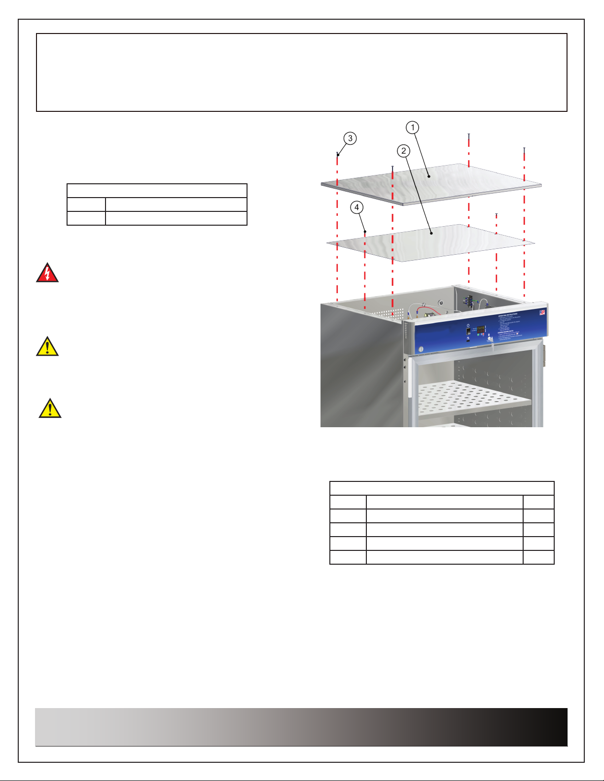
1. Remove four 8 X 1-5/8” self-tapping screws (Table
1, Item 4))from outside Top Panel (Table 1, Item 1).
Remove outside Top Panel and set aside (Fig. 1).
2. Remove two 8 X 1/2” self-tapping screws (Table 1,
Item 3) from the inside Top Panel (Table 1, Item 2).
Remove the inside Top Panel and set aside.
3. The motor can now be accessed through the
top and also from beneath to disassemble it and
install a new motor.
A. If necessary, remove a cabinet shelf to allow
easier access to the bottom of the Drawer
Assembly.
Go to Step 4, page 3.
Fig. 1: Remove/re-install Top Panels - Free Standing Units
Table 1 (Fig. 1)
Item # DESCRIPTION QTY
1 Outside Top Panel 1
2 Inside Top Panel 1
3 Screw, self-tapping 8 x 1/2” 2
4 Screw, self-tapping 8 x 1-5/8” 4
Information regarding this product is
subject to change without prior
notice.
Publication No. IFU-130 Rev A
Printed in USA
January 2018
1
Replacing Fan Motor for D and TS series
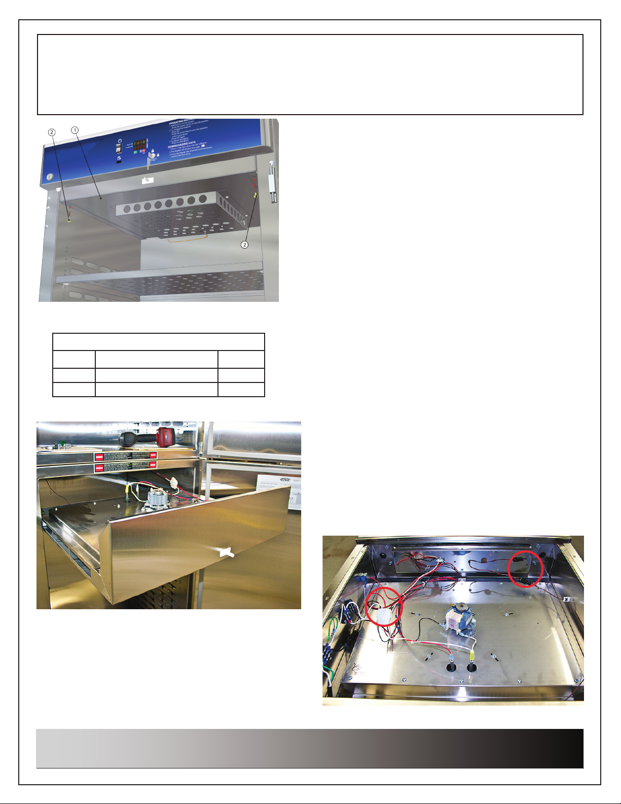
Fig. 2: Remove Drawer Assembly screws
Table 2 (Fig. 2)
Item # DESCRIPTION QTY
1 Drawer Assembly 1
2 Screw, 8-32 X 1/2, Pan Head 2
Instruction for Use -
Warming Cabinets
Working on Units in Recessed Spaces
For units situated in recessed spaces where the top
panels cannot be removed, skip Steps 2 and 3 on
page 1 which pertain to free standing units and use
this procedure instead.
Open the cabinet door and remove two 8-32 X 1/2
self tapping screws (Table 2, Item 2) located at the
bottom front of the Drawer Assembly.
A. Slide the Drawer Assembly (Table 3, Item 1) out
approximately 8” along the rail guide of the
cabinet. A top Drawer Assembly will come
out with the Header Assembly attached.
There is no Header Assembly attached to
Lower Drawer Assemblies.
i. In most cases, there is no need to
ii. For TS series cabinets, in addition to the
C. Fig. 3 shows a Lower Drawer Assembly on a
Dual Chamber cabinet that has been slid out
and its components ready for servicing.
D. After sliding out the Drawer Assembly, go to
Step 4.
Instruction for Use
completely remove the Drawer Assembly
from the cabinet to change the motor. If
complete drawer removal is preferred,
unplug the Drawer connectors, plugs and
probe wire (items circled in red as shown
in Fig. 4, Fig. 5 and Fig. 6).
connectors, plugs and probe wire, unplug
the Ethernet connection at the back.
Fig. 3: Lower Drawer Assembly - Dual Cabinet
Information regarding this product is
subject to change without prior
notice.
Fig. 4: Unplug connector and probe wire - D Series - Single
Publication No. IFU-130 Rev A
2
Printed in USA
January 2018

Instruction for Use -
Instruction for Use
Replacing Fan Motor for D and TS series
Warming Cabinets
Fig. 5: Unplug 2 connectors & probe wire - D series - Dual Fig. 6: Unplug 2 connectors, probe wire & plug - TS Series
4. Detach the fan blade by removing four 8-32 X 1/2 self-tapping screws (Table 3, Item 3) from the Air Box
(Table 3, Item 4). Note: Do not remove the Air Box from the Warming Unit. There is a probe wire attached to
the back of the Air Box that could become detached if removal is attempted. Let the Air Box hang from the
wire or let the edge of the Air Box rest against the lower panel.
5. Unscrew two 8-32 X 1/2 self tapping screws (Table 3, Item 3) to remove the Fan Guard (Table 3, Item 2).
Now the fan motor blade is accessible.
Table 3 (Fig. 7)
Item # DESCRIPTION QTY
1 Drawer Assembly 1
2 Fan Guard 1
3 Screw, 8-32 X 1/2, Phillips Pan Head 6
4 Air Box 1
Information regarding this product is
subject to change without prior
notice.
Fig. 7: Exploded view - Airbox and Fan Guard
3
Publication No. IFU-130 Rev A
Printed in USA
January 2018

Instruction for Use -
Instruction for Use
Replacing Fan Motor for D and TS series
Warming Cabinets
6. Secure the Fan Blade (Table 4, Item 3) to prevent it from turning.
7. The Motor Shaft stud (Table 4, Item 2) has left-hand threads. This
prevents the Fan Blade from coming off during normal operations.
Turn the 10-32 Hex Nut (Table 4, Item 4) to the right to remove it from
the Motor .
8. Remove the Fan Blade and the 10-32 at washer (Table 4, Item 1)
from the Motor Assembly.
9. Once the Fan Blade is removed, re-attach the 10-32 nut (along with
the at washer) to the Motor Shaft, and tighten the nut to nger tight
ONLY. Remember, the 10-32 nut has left-hand threads and must be
turned to the left to tighten it on the motor shaft
Table 4 (Fig. 8)
Item # DESCRIPTION QTY
1 Washer, 10-32 Flat 1
2 Motor Shaft Stud 1
3 Fan Blade 1
4 Nut, 10-32 1
Fig. 8: Exploded View - Fan
Disconnecting and Removing Fan Motor
10. Remove the power (black) wire (Table 5, Item 1) from the Fan Motor (Table 5, Item 2).
11. Remove the ground (white) wire (Table 5, Item 3) from the Fan Motor.
12. From below the Drawer Assembly, loosen the three 10-32 X 1/2” pan head screws located under the fan
motor (Table 5, Item 4).
13. Lift out the old Fan Motor from the top. (Table 5 Item 2).
Fig. 9: Motor Wire Connections
Information regarding this product is
subject to change without prior
notice.
Fig. 10: Remove Motor Screws
4
Table 5 (Fig. 9 & Fig. 10)
Item # DESCRIPTION QTY
1 Power Lead, Fan Motor,
Black
2 Fan Motor 1
3 Ground Lead, Fan Motor,
White
4 Screw 10-32 X 1/2” Pan
head with External
Lockwasher
Publication No. IFU-130 Rev A
Printed in USA
January 2018
1
2
3

Instruction for Use -
Replacing Fan Motor for D and TS series
Warming Cabinets
Install New Fan Motor
1. Place the new Fan Motor (Table 6, Item 1) on the top of
the Element Tray panel in the Drawer Assembly (Table
6, Item 2) and line up the motor fastener holes with the
holes on the tray panel.
2. From below, thread the 3 pan head screws back into
the Element Tray panell and into the base of the new
Fan Motor.
3. Securely tighten the 3 pan head screws to
secure the motor rmly against the Element
Tray panel.
Table 6 (Fig. 11)
Item # DESCRIPTION QTY
1 Fan Motor 1
2 Element Tray panel 1
Connecting the New Fan Motor
1. Attach the power (black) wire (Table
7, Item 1) to the Fan Motor (Table 7,
Item 2).
2. Attach the ground (white) wire (Table
7, Item 3) to the Fan Motor.
Fig. 11: Install New Motor
Instruction for Use
Table 7 (Fig. 12)
Item # DESCRIPTION QTY
1 Power Lead, Fan Motor, Black 1
2 Fan Motor 1
3 Ground Lead, Fan Motor, White 2
Attaching the Fan Blade
Fig. 12: Motor Wire Connections
1. Attach the 10-32 at washer (Table 8, Item 1) on the
motor shaft.
2. Attach the new Fan Blade (Table 8, Item 3) by
pushing it upwards on the motor shaft until it rests
against the 10-32 at washer installed in Step 1.
3. Secure the Fan Blade preventing it from turning.
4. Install the 10-32 nut (Table 8, Item 4) on the motor
shaft until it is tight against the new Fan Blade.
NOTE: The nut counterbore side faces the blade
(Fig. 14). Once applied, the fan should not wobble.
5. The Motor Shaft Stud (Table 8, Item 2) has left-hand
threads. This prevents the Fan Blade from coming
off during normal operations. Turn the 10-32 Hex Nut
to the left to install it on the threaded motor shaft.
Fig. 13: Exploded View - Fan
Item # DESCRIPTION QTY
Fig. 14: Counterbore side to blade
Table 8 (Fig. 13)
1 Washer, 10-32 Flat 1
2 Motor Shaft Stud 1
3 Fan Blade 1
4 Nut, 10-32 1
Fig. 15: Side faces away from blade
Information regarding this product is
subject to change without prior
notice.
Publication No. IFU-130 Rev A
Printed in USA
January 2018
5

Instruction for Use -
Instruction for Use
Replacing Fan Motor for D and TS series
Warming Cabinets
6. Place the Fan Guard (Table 9, Item 2) against the bottom of the Drawer Assembly and align the two tabs
with holes in the bottom of the drawer. Install two 8-32 X 1/2” screws (Table 9, Item 3) and attach the guard
to the drawer.
7. Place the Air Box (Table 9, Item 4) over the Fan Guard on the bottom of the Drawer Assembly (Table 9, Item
1). Align the four holes in the air box with four holes in the bottom of the drawer. Make sure that the probe
wire that is attached to the Air Box is to the rear of the Warming Unit.
Table 9 (Fig. 16)
Item # DESCRIPTION QTY
1 Drawer Assembly 1
2 Fan Guard 1
3 Screw, 8-32 X 1/2, Pan Head 6
4 Air Box 1
Fig. 16: Exploded view - Airbox and Fan Guard
8. Install four 8-32 X 1/2” screws (Table 9, Item 3)) to attach the air box to the bottom of the drawer.
9. Finishing the Cabinet Re-assembly for Free Standing Units
A. Re-install the outer and inner top panels, securing with two 8 X 1-5/8” self-tapping screws (Table 1, Item
4) to the Inside Top Panel (Table 1, Item 1) and four 8 x 1-5/8” self-tapping screws to the Outside Top
Panel (Fig. 1).
10. Finishing the Cabinet Re-assembly for Units Situated in Recessed Walls
A. Plug in the unplugged connectors, plugs and probe wire. (Fig. 4, Fig. 5 or Fig. 6). If a TS series unit, also
plug in the Ethernet connection.
B. Slide the Drawer Assembly back into the Warming Cabinet.
iii. Important: Ensure proper door switch operation - For both steel and glass door units, the top Drawer
Assembly should be re-installed to sit ush with the front surface of the door frame edge. For steel
door units, the lower Drawer Assembly front surface should sit ush with the front surface of the door
frame edge. For glass door units, the lower Drawer Assembly front surface should be re-ijnstalled to
sit recessed up to 1/8” below the front surface of the door frame edge.
D. Align the two holes (located bottom-front) on the drawer with the two holes in the rail guides in the
Warming Cabinet. Secure the Drawer Assembly to the cabinet guide rails by attaching two 8-32 X 1/2”
self-tapping screws (Table 1, Item 2) into the holes of the guide rails of the cabinet (Fig. 1).
Information regarding this product is
subject to change without prior
notice.
Publication No. IFU-130 Rev A
Printed in USA
January 2018
6
 Loading...