

Mac Medical PT1001, PT1001-31 Instruction Manual

INSTRUCTION MANUAL
PT1001 & PT1001-31
(General Transport Stretcher)
MAN-037 Rev C 11/2017
Read and understand all of the instructions and safety
information in this manual before operating this product.
© 2017 MAC Medical, Inc.

Instruction Manual
DESCRIPTION OF PRODUCT
The General Transport Stretcher is capable of transporting 750 lbs. It features directional movement, cornering
and pivoting, Trendelenburg/reverse Trendelenburg bed positions, six IV pole congurations, ergonomically
located oxygen tank holder, six brake/steer locations, Dual Fowler assisted adjustable back rest and large
storage area for patient belongings.
The General Transport Stretcher comes as either a 29” bed width or a 31” bed width.
PURPOSE OF THIS MANUAL
This manual provides the parts list, operation, cleaning and maintenance instructions for the General Transport
Stretcher.
This manual pertains to both the PT1001 (29” bed with) and the PT1001-31 (31” bed width).
To place an order, contact our customer service
department at 618-476-3550 or 877-828-9975 or
by email at sales@macmedical.com
TABLE OF CONTENTS
Warnings and Cautions Icon Key 3
Warnings and Cautions When Installing or Operating This Product 3
General Material Specications of the PT1001 and PT1001-31 General Transport Stretcher 4
Overall Stretcher Dimensions 4
Parts List of PT1001 and PT1001-31 General Transport Stretcher 5
Operation of the PT1001 General Transport Stretcher 8
Fowler Adjustment for PT1001 and PT1001-31 General Transport Stretcher 13
Stretcher Optional Features 15
Maintenance 15
Cleaning 15
Transportation and Storage Conditions 15
Transportation Damage And Claims 16
Limited Lifetime Warranty 16
KEEP THIS MANUAL
MAN-037
2
www.macmedical.com
Instruction Manual
Warnings and Cautions Icon Key
The following is a list identifying the various warning and caution icons used in this manual.
Icon Type Icon Description
Cautions (Yellow triangle with an exclamation point) indicate
the potential minor injury to personnel and damage to
equipment.
Note: The exclamation point will not be visible where only
equipment damage is present.
Warnings and Cautions When Installing or Operating This Product
1. Prior to installation or operation, the user must read the warnings and cautions listed below.
2. The following is a list of the safety precautions, which must be observed when operating this equipment.
WARNINGS indicate the potential for danger to personnel.
CAUTIONS indicate the potential for damage to equipment.
These precautions are repeated (in whole or in part), where applicable, throughout the manual. It is important
to review these precautions before using the equipment.
WARNING-INJURY HAZARD -
REPAIRS AND ADJUSTMENTS should be only attempted by experienced service agents fully acquainted with
this equipment. The use of inexperienced, unqualied persons to service the equipment, or the installation of
unauthorized parts, could cause serious personal injury, or result in costly damage.
CAUTION-POSSIBLE EQUIPMENT DAMAGE -
When cleaning the stretcher - See complete Cleaning Instructions in this manual.
NOTE: This product is to be used strictly for the purpose it was designed for. If this product is used in a manner
not specied by MAC Medical, Inc., the protection provided by the equipment may be impaired. MAC
Medical, Inc disclaims all liability for the consequences of this product being used for purposes other than its
intended design. Product modication or misuse can be dangerous. MAC Medical, Inc disclaims all liability for
the consequences of product alterations or modications, as well as for the consequences which might result
from the combination of this product with other products, whether supplied by MAC Medical, Inc or by other
manufacturers, unless such a combination has been specically endorsed by MAC Medical, Inc.
MAN-037
3
www.macmedical.com
Instruction Manual
General Material Specications of the PT1001 and PT1001-31 General Transport Stretcher
Chassis Shroud: LDR33/1 552 ABS FS8039 Mattress Pad: Polyurethane Foam Core
Wheel Lock Pedal: Hot Rolled Bar Stock Pedals: Flexible PVC
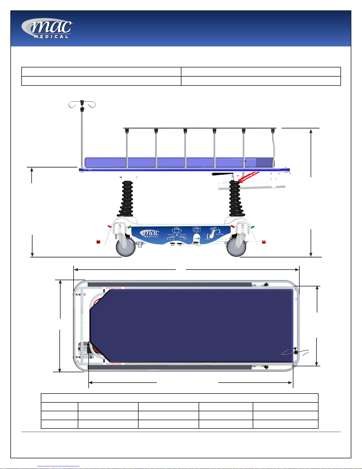
Overall Stretcher Dimensions
[889 mm]
35”
(fully extended height)
[558.8 mm]
22”
(lowest height position)
[1295.39 mm]
51” (fully
extended height)
[965.19 mm]
38” (lowest
height position)
A
B
D “Patient Surface”
Width and Length Dimensions (in millimeters and inches)
Model # A B C D
PT1001 [2116.14mm] 83 5/16” [852.49mm] 33 9/16” [739.77mm] 29 1/8” [1916.11mm] 75 7/16”
PT1001-31 [2116.14mm] 83 5/16” [903.29mm] 35 9/16” [790.57mm] 31 1/8” [1916.11mm] 75 7/16”
C
“Patient
Surface”
MAN-037
4
www.macmedical.com
Instruction Manual
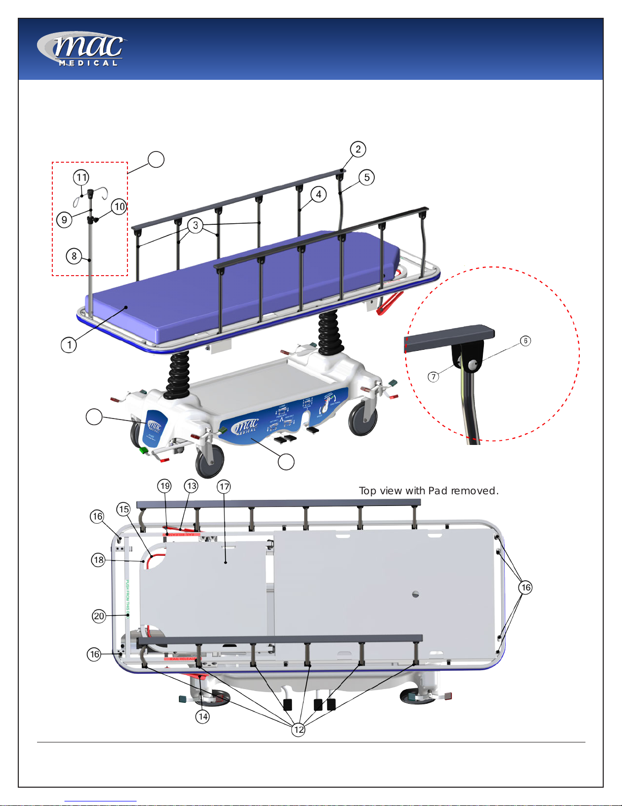
Parts List of PT1001 and PT1001-31 General Transport Stretcher
The main structural and operational Stretcher components called out in the following illustrations are identied
in the table on Page 7. The operational components will be covered in more detail in this installation manual.
39
For either 29” width
or 31” width stretchers
40
40
Detail A
Top view with Pad removed.
MAN-037
5
www.macmedical.com
 Loading...