

Mac Medical DWC24-TL, DWC24-TL-D Installation Instructions Manual
INSTALLATION INSTRUCTIONS: Replacing a Standard Warmer
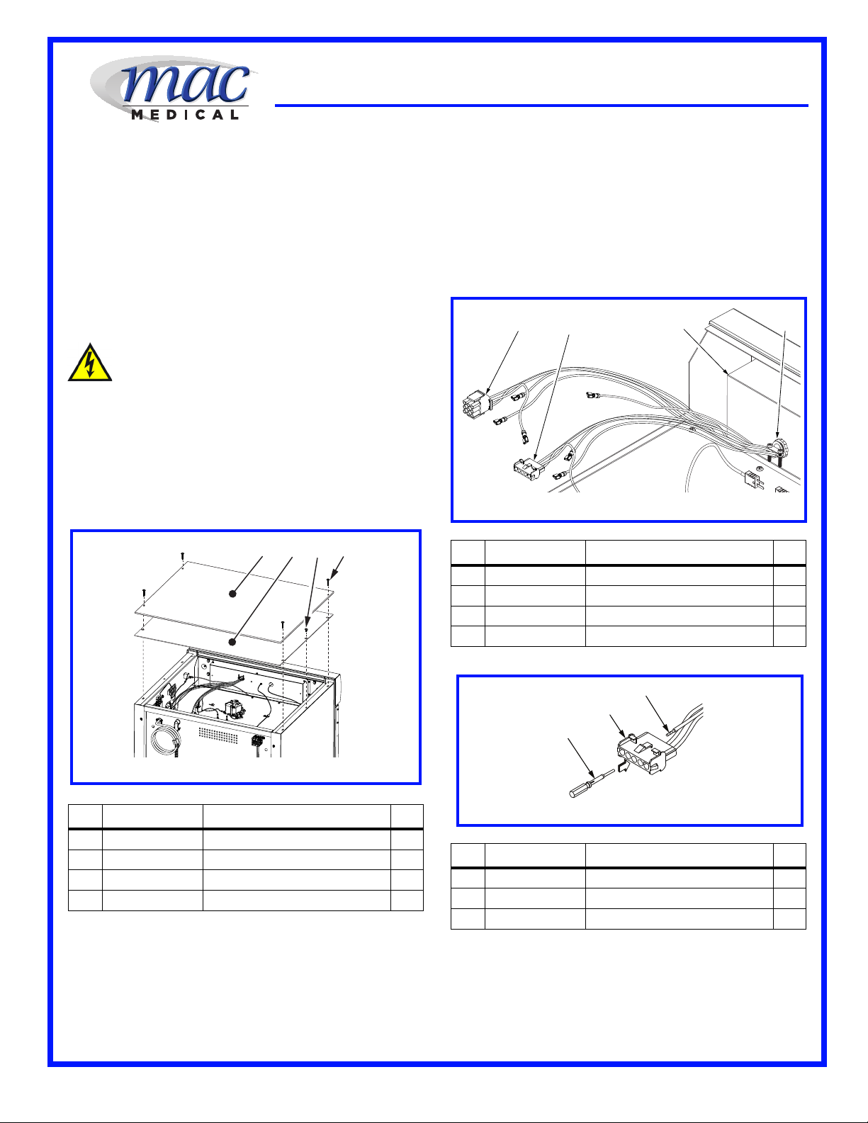
Figure 1: Removing Inside and Outside Top Panel
1
2
3
4
Figure 2: Loosening Wire Connector on Electrical Box
12
3
4
Figure 3: Removing Wires from Circuit Plug
1
2
Header (DWC24-TL) with a Data Log Header (DWC24-TL-D)
A: Removing Standard Warmer Cabinet Header
(p/n: DWC24-TL)
The Standard Warmer Header for a DWC24-TL
Dual Warmer Cabinet can be easily replaced
with a DWC24-TD-D Warmer Cabinet Header
with a Data Logger option.
1. Disconnect all electrical power to the Warming
Cabinet by removing the power cord from the
electrical supply. If the unit is hard-wired to
facility power, turn OFF the circuit breaker.
CAUTION:
Failure to remove the power cord from
the electrical supply can result in severe
electrical shock and even death to
personnel as well as severe damage to
the equipment.
2. The Outside and Inside Top Panels must be
removed first. See Figure 1.
3. Remove four 8 X 1-5/8” self-tapping screws
from Outside Top Panel. Remove Outside
Top Panel and set aside. See Figure 1.
1. There is no specific order in removing all
wiring to the Header, just specific steps that
allows the wiring to pass safely through the
electrical box.
2. Loosen two screws on the 3/8” straightthrough electrical connector mounted on the
back side of the Warmer Cabinet Electrical
Box (just behind the Header). See Figure 2.
REF P/N DESCRIPTION
1 W0199 Connector, 9 Circuit Plug 1
2 W0198 Connector, 5 Circuit Plug 1
3 SMW0032 Cover, Electrical Box 1
4 W0140 Connector, 3/8” Straight 1
QTY
REF P/N DESCRIPTION
1 SMW0027 Outside Top Panel 1
2 SMW0028 Inside Top Panel 1
3 H0012-01 Screw, Self-Tapping, 8 X 1/2” 2
4 H0012-02 Screw, Self-Tapping, 8 X 1-5/8” 4
4. Remove two 8 X 1/2” self-tapping screws from
Inside Top Panel. Remove Inside Top Panel
and set aside. See Figure 1.
The Standard Warmer Header for a DWC24-TL
Dual Warmer Cabinet can be removed from a
standard dual warming cabinet without removing
the Upper Drawer Assembly (p/n: W0288).
IFU - 033 Rev.A
3
QTY
REF P/N DESCRIPTION
1 16AWG Tool, Pin Extraction 1
2 W0198 Connector, 5 Circuit Plug 1
3 16AWG Wire, Crimped Terminal End 1
3. Use a Pin Extraction Tool (for 16AWG wire) to
QTY
remove the wire leads from the 9-/5-Connector
Circuit Plugs. See Figure 3.
CAUTION: Use ONLY a Pin Extraction Tool
designed for the specific wire size
1
02/23/2015
INSTALLATION INSTRUCTIONS: Replacing a Standard Warmer
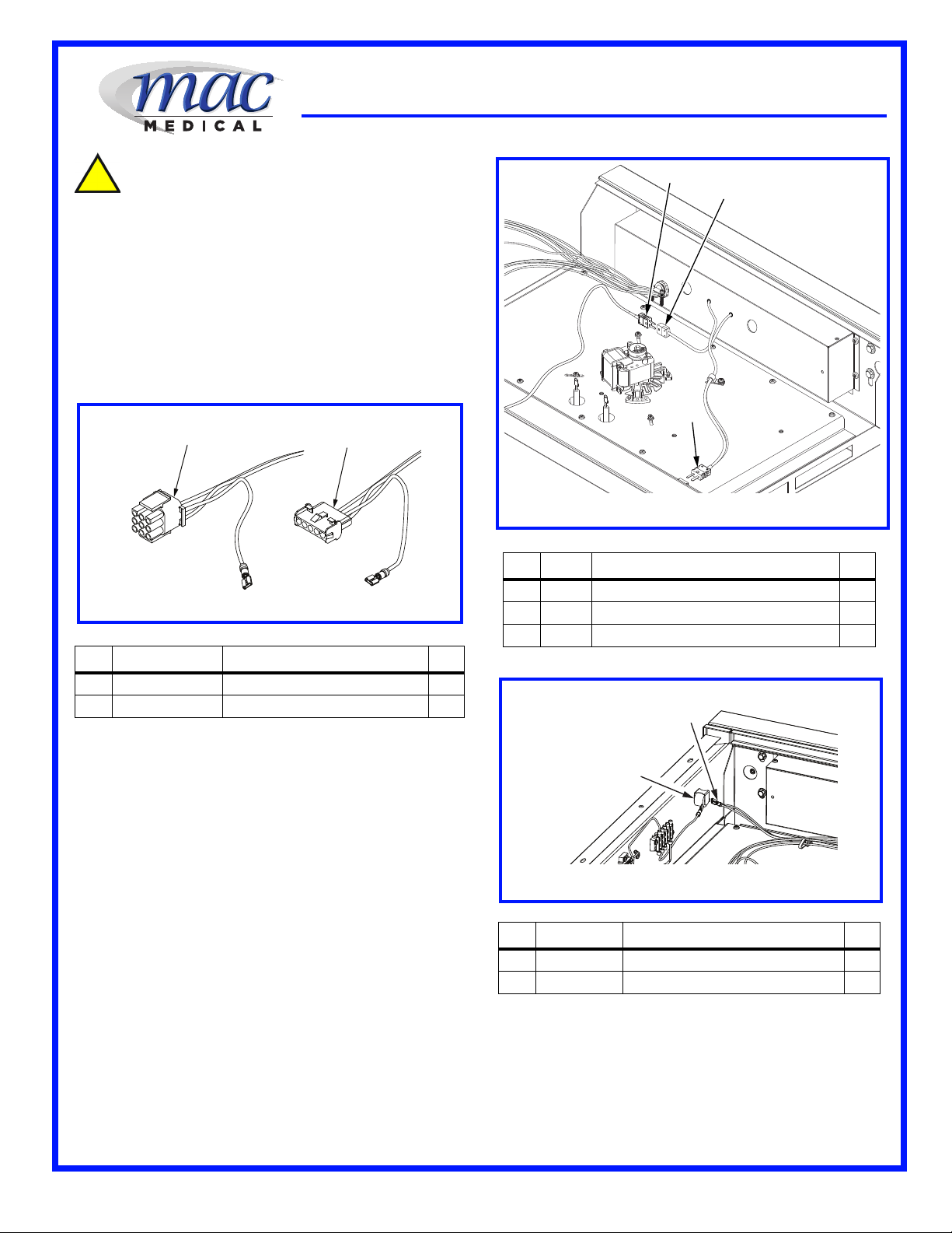
Figure 4: Molded Power Connectors
1
2
Figure 5: Disconnecting Thermocouple Connectors
1
3
2
Figure 6: Over Temperature Alarm Buzzer
1
2
Header (DWC24-TL) with a Data Log Header (DWC24-TL-D)
used. DO NOT attempt to push the
wire terminal out of the connector
with a small Phillips screwdriver or
similar tool. This method will
damage both the connector and
wire resulting in replacement.
4. There are two molded connectors used. A 9pin is used for the Lower Warmer connection
and a 5-pin is used for the Upper Warmer
connection. It is recommended that before
disconnecting the wires, each set should be
taped together and marked to prevent placing
the wrong wire in a connector. See Figure 4.
REF P/N DESCRIPTION
1 W0199 Connector, 9 Circuit Plug 1
2 W0198 Connector, 5 Circuit Plug 1
5. There are two (an upper and lower) Thermocouple connections that feeds data to the
header from the upper and lower warmer
units. These Thermocouple connectors are
located in the upper drawer of the Warming
Cabinet.
6. When exchanging the header, each Thermocouple connector must be disconnected. See
Figure 5, Items 1 through 2. Items 1 (p/n:
W0037) is a male connection and does not go
through the Header and does not need to be
taken apart. Item number 2, is a female
receptacle, (p/n: W0038) and must have the
wires removed before the header can be
removed.
7. Remove the two screws on one female
receptacle and one male receptacle and lift off
the cover. See Figure 5, Items 2 and 3. Place
the screws and cover in an area where they
will not be misplaced. Loosen the two screws
on the inside and pull the two wires away from
the receptacle.
QTY
REF P/N DESCRIPTION
1 W0037 Connector, Male, Upper Chamber 2
2 W0038 Connector, Female, Upper Chamber 1
3 W0037 Connector, Male Lower Chamber 1
REF P/N DESCRIPTION
1 W0013 Buzzer, Over Temperature Alarm 1
2 W0118 Terminal, Over Temperature Alarm 1
8. The only remaining wires to disconnect are the
lead to the Over Temperature Alarm Buzzer
and the power leads to the 5-Position Terminal
block on the cabinet side wall. See Figure 7.
9. The Over Temperature Alarm Buzzer lead pulls
directly off the buzzer and out through the
Electrical Box behind the Header. The
connector will consist of two wires in the
QTY
QTY
IFU - 033 Rev.A
2
02/23/2015
 Loading...