

Mac Medical SWC243024, SWC243036, SWC242436, SWC182464, SWC242464 Installation Operation & Maintenance
...
INSTRUCTION MANUAL
Installation - Operation - Maintenance
MAN-001 Rev J
D-Series Warming Cabinets
OSHPD
R
C
Read and understand all of the instructions and safety
information in this manual before operating this product.
© 2018 MAC Medical, Inc.
Pre-Approved
10/2018

Instruction Manual
TAble Of COnTenTS
Summary 3
D-Series Warming Cabinet Models
Interior Dimensions, Cubic Foot Capacity, Approximate Capacity
General Specications
Main Features of a Typical Warming Cabinet
Warnings and Cautions
Unpacking Instructions
Receiving Requirements
Installing D-Series Warming Cabinets
Environmental Conditions
Installation
Testing before Using
Installing Warming Cabinet Leg Levelers
Optional Direct Wiring Using Facility Power Supply
Basic Operation
Recommended Settings
Loading Contents in Cabinet
In Case of Power Failure
Explanation of the Controls
Operation of Display Panel
Installing the Shelves
Adjusting the Shelves
Installing and Adjusting Optional Roller Basket Shelves
Unloading the Warming Cabinet
Retrieval of Recorded Temperatures
Turning Off the Warming Cabinet
Troubleshooting
Overheat Alarm (HI) Condition
Cleaning Stainless Steel Warming Cabinets
Preventative Maintenance Checklist
Replacement Parts - General
Replacement Parts - Header Assembly and Electrical Drawer
Optional Cabinet Bases, Mobile Bases and Mobile Stands
Steel or Glass Door Hinge Reversal
Remove Panels
Remove Header Assembly Box & Relocate Cam Lock
Purchase Parts Needed for Cam Lock Reversal
Glass Door Hinge Reversal and Re-installation
Steel Door Hinge Reversal and Re-installation
Purchase Parts Needed for Door Hinge Reversal
Wiring Diagram - Single Chamber Warmers
Wiring Diagram - Dual Chamber Warmers
Wiring Diagram - Triple Chamber Warmers
Index
41
Limited Lifetime Warranty
7
9
11
11
12
12
15
18
18
21
28
44
4
5
8
12
12
13
14
15
15
15
16
17
19
20
20
20
21
22
23
24
25
27
28
29
29
32
35
35
38
39
40
MAN-001
2
www.macmedical.com
Summary
Instruction Manual
DeSCRIPTIOn Of PRODUCT
This manual covers the D-Series (Data
Logging) blanket and uid warming cabinets,
manufactured for commercial use only. These
include the single, dual and triple chamber units.
PURPOSe Of THIS MAnUAl
This manual is to provide the user instructions in
the installation, operation and maintenance of
the D-Series warming cabinets.
This manual also contains general
specications, warnings and cautions.
Indications for Use:
The MAC Medical Inc. Blanket and Solution Warming Cabinets are designed to store and warm blankets,
hospital linens, irrigation uids, and/or injection uids in accordance with recommended warming
temperatures and storage time guidelines provided by the manufacturers of such products.
MAN-001
3
www.macmedical.com
Instruction Manual
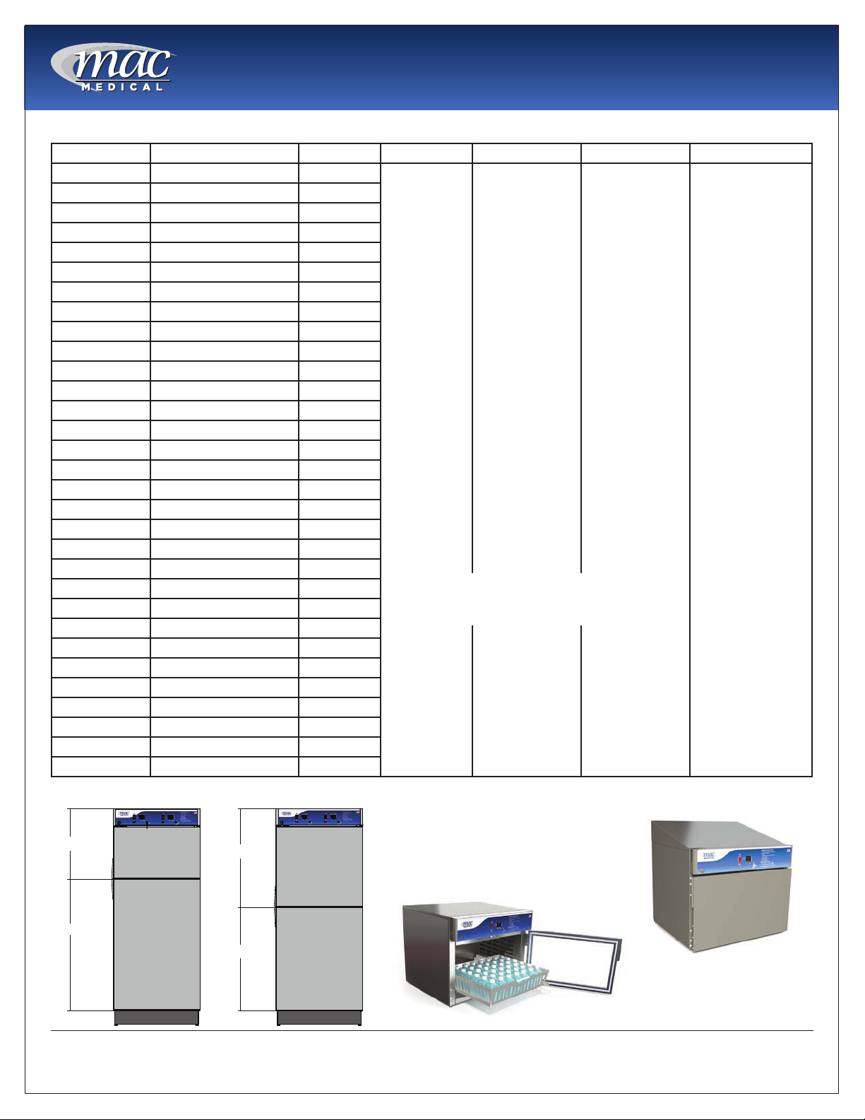
D-Series Warming Cabinet Models
Model # Overall Size Chambers Door Type Door Hinge base Style Other Options
SWC151822 17.25"D x 18"W x 22"H Single G=Glass Door
SWC182424 20.5"D x 24"W x 24.5"H Single
SWC242424 26.5”D x 24”W x 24.5”H Single
SWC183024 20.5"D x 30"W x 24.5"H Single
SWC243024 26.5"D x 30"W x 24.5"H Single
SWC182436 20.5”D x 24”W x 36”H Single
SWC183036 20.5"D x 30"W x 36"H Single
SWC242436 26.5”D x 24”W x 36”H Single
SWC243036 26.5"D x 30"W x 36"H Single
SWC182464 20.5"D x 24"W x 64.75"H Single
SWC242464 26.5"D x 24"W x 64.75"H Single
SWC183064 20.5"D x 30"W x 64.75"H Single
SWC243064 26.5"D x 30"W x 64.75"H Single
SWC182474 20.5”D x 24”W x 74.5”H Single
SWC183074 20.5"D x 30"W x 74.5"H Single
SWC242474 26.5”D x 24”W x 74.5”H Single
SWC243074 26.5"D x 30"W x 74.5"H Single
DWC182464T* 20.5"D x 24"W x 64.75"H Dual
DWC242464T* 26.5"D x 24"W x 64.75"H Dual
DWC183064T* 20.5"D x 30"W x 64.75"H Dual
DWC243064T* 26.5"D x 30"W x 64.75"H Dual
DWC182474T* 20.5"D x 24"W x 74.5"H Dual
DWC242474T* 26.5"D x 24"W x 74.5"H Dual
DWC183074T* 20.5"D x 30"W x 74.5"H Dual
DWC243074T* 26.5"D x 30"W x 74.5"H Dual
DWC182474E** 20.5”D x 24”W x 74.5”H Dual
DWC183074E** 20.5"D x 30"W x 74.5"H Dual
DWC242474E** 26.5”D x 24”W x 74.5”H Dual
DWC243074E** 26.5"D x 30"W x 74.5"H Dual
TWC183078 20.5"D x 30"W x 78.75"H Triple
TWC243078 26.5"D x 30"W x 78.75"H Triple
Blank=Stainless
Steel Door
(Standard)
ţ Only available for Triple Chamber Unit
ţţ Only available for Dual and Triple Chamber Units
LH=Left Hinge
Blank = Right
Hinge (Standard)
2B = 2” Base
4B = 4” Base
6B = 6” Base
NB = No Base
MB = Mobile Base
220 = 220/240V
Power Supply
C = Celsius
R1 = Recessed
Unit with Insulation
Wrap, no Top Panel,
no Side Panels and
no Trim Kit.
R2 = Recessed Unit
with Top Panel, Side
Panels, and Trim Kit.
SB = Seismic Braces
WB = Roll Out
Basket
P = Pass Through
Chamber
IV = IV/Injection
Fluids
ST = Sloped Top
EL = Electronic
Keypad lock
ţ DL = Intermediate
Chamber Door Lock
(triple chamber
units)
ţţ LDL = Lower
Chamber Door
Lock (dual/triple
chamber units)
* = Chambers in Thirds ** = Equal Chambers
1/3
2/3
1/2
1/2
MAN-001
Sloped Top
Roll Out basket
4
www.macmedical.com

Interior Dimensions, Cubic foot Capacity, Approximate Capacity
Instruction Manual
Model # Upper or single
Chamber
(h x w x d) in
inches
SWC151822 14.0 x 14.0 x 11.63 n/a n/a/ 1.30 n/a n/a 5 - 6 blankets, 8 bottles
SWC182424 15.25 x 20.0 x 17.0 n/a n/a 3.0 n/a n/a 9 blankets, 8 bottles
SWC242424 15.25 x 20.0 x 23.0 n/a n/a 4.06 n/a n/a 9 blankets, 12 bottles
SWC183024 15.25 x 26.0 x 17.0 n/a n/a 3.9 n/a n/a 18 blankets, 8 bottles
SWC243024 15,25 x 26.0 x 23.0 n/a n/a 5.27 n/a n/a 18 blankets, 20 bottles
SWC242436 36.0 x 20.0 x 23.0 n/a n/a 6.7 n/a n/a 16 blankets, 25 bottles
SWC182436 25.0 x 20.0 x 17.0 n/a n/a 5.0 n/a n/a 16 blankets, 20 bottles
SWC183036 25.0 x 26.0 x17.0 n/a n/a 6.39 n/a n/a 32 blankets, 36 bottles
SWC243036 25.0 x 26.0 x 23.0 n/a n/a 8.65 n/a n/a 32 blankets, 40 bottles
SWC182464 49.5 x 20.0 x 17.0 n/a n/a 9.74 n/a n/a 32 blankets, 48 bottles
SWC242464 51.0 x 20.0 x 23.0 n/a n/a 13.60 n/a n/a 80 blankets, 120 bottles
SWC183064 51.0 x 26.0 x 17.0 n/a n/a 13.05 n/a n/a 66 blankets, 72 bottles
SWC243064 51.0 x 26.0 x 23.0 n/a n/a 17.65 n/a n/a 80 blankets, 120 bottles
SWC182474 61.0 x 20.0 x 17.0 n/a n/a 12.00 n/a n/a 32 blankets, 60 bottles
SWC183074 61.0 x 26.0 x 17.0 n/a n/a 15.60 n/a n/a 80 blankets, 72 bottles
SWC242474 61.0 x 20.0 x 23.0 n/a n/a 16.24 n/a n/a 80 blankets, 120 bottles
SWC243074 61.0 x 26.0 x 23.0 n/a n/a 21.1 n/a n/a 80 blankets, 120 bottles
DWC182464T* 13.5 x 20.0 x 17.0 n/a 24.5 x 20.0 x
DWC242464T* 13.5 x 20.0 x 23.0 n/a 24.5 x 20.0 x
DWC183064T* 13.5 x 26.0 x 17.0 n/a 24.5 x 26.0
DWC243064T* 13.5 x 26.0 x 23.0 n/a 24.5 x 26.0 x
DWC182474T* 15.25 x 20.0 x 17.0 n/a 34.5 x 20.0 x
DWC242474T* 15.25 x 20.0 x 23.0 n/a 34.5 x 20.0 x
DWC183074T* 15.25 x 26.0 x 17.0 n/a 34.5 x 26.0 x
DWC243074T* 15.25 x 26.0 x 23.0 n/a 34.5 x 26.0 x
DWC182474E** 25.0 x 20.0 x 17.0 n/a 26.0 x 20.0 x
DWC183074E** 25.0 x 26.0 x 17.0 n/a 26.0 x 26.0 x
DWC242474E** 25.0 x 20.0 x 23.0 n/a 26.0 x 20.0 x
DWC243074E** 25.0 x 26.0 x 23.0 n/a 26.0 x 26.0 x
TWC183078 11.25 x 26.0 x 17.0 10.75 x 26.0
TWC243078 11.25 x 26.0 x 23.0 10.75 x 26.0
Middle
Chamber
(h x w x d)
in inches
x 17.0
x 23.0
lower
Chamber
(h x w x d)
in inches
17.0
23.0
x17.0
23.0
17.0
23.0
17.0
23.0
17.0
17.0
23.0
23.0
18.5 x 26.0
x 17
18.5 x 26.0 x
23.0
Cubic foot
Capacity
Upper or single
Chamber
2.65 n/a 4.82 26 blankets, 36 bottles
3.59 n/a 6.52 52 blankets, 80 bottles
3.45 n/a 6.27 50 blankets, 54 bottles
4.67 n/a 8.48 52 blankets, 96 bottles
2.65 n/a 6.79 32 blankets, 48 bottles
4.06 n/a 9.18 52 blankets, 80 bottles
3.45 n/a 8.82 52 blankets, 72 bottles
5.28 n/a 11.93 52 blankets, 120 bottles
4.97 n/a 5.24 44 blankets, 48 bottles
6.39 n/a 6.65 64 blankets, 72 bottles
6.65 n/a 6.99 64 blankets, 80 bottles
8.65 n/a 8.99 64 blankets, 120 bottles
2.88 2.75 4.73 62 blankets, 54 bottles
3.89 3.72 6.4 62 blankets, 90 bottles
Cubic foot
Capacity
Middle
Chamber
Cubic foot
Capacity
lower
Chamber
Approximate
Capacity
(blankets or 1 liter
solution bottles)
MAN-001
5
www.macmedical.com
Instruction Manual
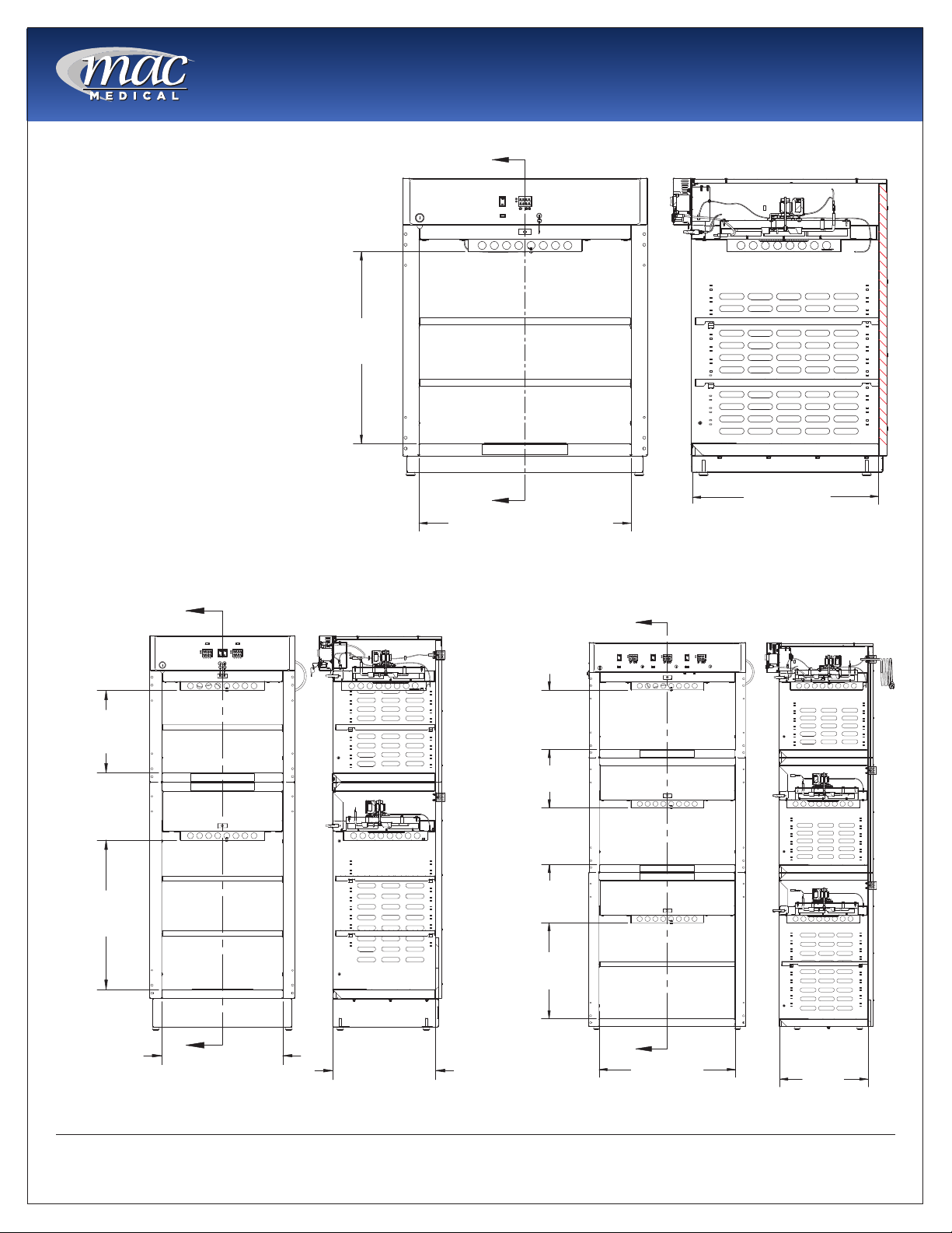
Usable Chamber Space
The usable chamber space of the
single, dual and triple cabinets
is slightly different from the
height, width, and depth interior
dimensions in the table on the
previous page.
Note that the usable chamber
inner height is measured from
the bottom of the air box to the
bottom of the chamber.
(In these views, the doors were
removed for clarity.)
USABLE
INNER HEIGHT
DIMENSION
A
A
CHAMBER WIDTH DIMENSION
Fig. 1: Single Chamber Unit Usable Space
CHAMBER DEPTH
DIMENSION
SECTION A-A
A
USEABLE
INNER HEIGHT
DIMENSION
USEABLE
INNER HEIGHT
DIMENSION
A
CHAMBER
WIDTH
DIMENSION.
Fig. 2: Dual Chamber Unit Usable Space
SECTION A-A
CHAMBER
DEPTH
DIMENSION.
A
USEABLE
INNER HEIGHT
DIMENSION
USEABLE
INNER HEIGHT
DIMENSION
USEABLE
INNER HEIGHT
DIMENSION
A
CHAMBER
WIDTH
DIMENSION
Fig. 3: Triple Chamber Unit Usable Space
SECTION A-A
CHAMBER
DEPTH
DIMENSION
MAN-001
6
www.macmedical.com
Instruction Manual
General Specications
Cabinet Construction and Material
• 300 Stainless Steel (all panels, header and doors) Double walled construction with insulation. Doors are
double pan stainless steel.
• Fully insulated to provide uniform heating
• Optional Glass door are double paned tempered glass framed with aluminum.
• Doors are fully gasketed and hinged on right side or optionally on the left side.
Factory Presets
• All units are preset to measure temperature in Fahrenheit (unless the unit was specically ordered to be
preset for Celsius.)
Power Requirements
• 120VAC, 60Hz, Single Phase, 15 AMP,
Ground Fault Interrupter Circuit (GFIC)
protected electrical outlet, or 220 VAC,
60Hz, Single Phase, 7 AMP, GFIC protected
electrical outlet (by others) installed
per local building codes and provides
protective grounding.
• Cabinets are supplied with a 7 foot (2.3m)
long, 14-3 SJT power cord with a 120V
(NEMA 15P) hospital grade plug. For multichambered units, ON/OFF switches are
supplied for each chamber.
• All individual electronic components are
Underwriter’s Laboratory (UL) approved
and recognized.
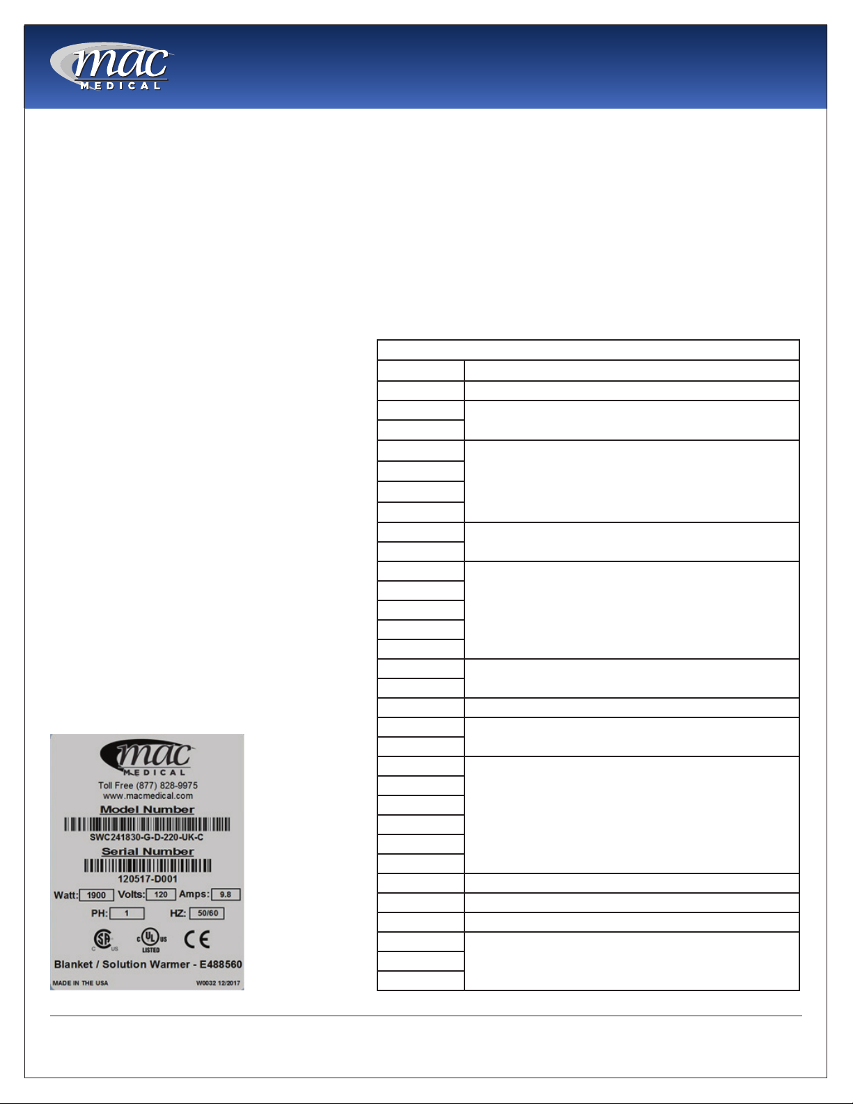
Power Specications are located on the unit
identication rating tag (see Fig. 4) which is
permanently attached on the inside of the
door or on the back of the upper chamber.
Model # Description
SWC151822 120V, 2.08 Amp, 50/60Hz, .25 kWh (Avg.), 853 BTU/hr (Avg.)
SWC182424
SWC182436
SWC242424
SWC242436
SWC243024
SWC243036
SWC183024
SWC183036
SWC182464
SWC182474
SWC183074
SWC242474
SWC243074
SWC242464
SWC243064
SWC183064 120V, 6.3 Amp, 50/60 Hz, .41 kWh (Avg.), 1400 BTU/hr (Avg.)
DWC183064T
DWC242464T
DWC182464T
DWC182474E
DWC182474T
DWC243064T
DWC242474E
DWC242474T
DWC183074T 120V, 8.3 Amp, 50/60 Hz, .82 kWh (Avg.), 2047 BTU/hr (Avg.)
DWC243074T 120V, 12.5 Amp, 50/60 Hz, .90 kWh (Avg.), 3071 BTU/hr (Avg.)
DWC183074E 120V, 11.4 Amp, 50/60 Hz, .82 kWh (Avg.), 2798 BTU/hr (Avg.)
DWC243074E
TWC243078
Electrical Specications by Model
120V, 2.9 Amp, 50/60 Hz, .23 kWh (Avg.), 785 BTU/hr (Avg.)
120V, 6.3 Amp, 50/60 Hz, .45 kWh (Avg.), 1535 BTU/hr (Avg.)
120V, 5.7 Amp, 50/60 Hz, .45 kWh (Avg.), 1535 BTU/hr (Avg.)
120V, 6.5 Amp, 50/60 Hz, .47 kWh (Avg.), 1604 BTU/hr (Avg.)
120V, 6.5 Amp, 50/60 Hz, .41 kWh (Avg.), 1604 BTU/hr (Avg.)
120V, 8.3 Amp, 50/60 Hz, .60 kWh (Avg.), 2047 BTU/hr (Avg.)
120V, 8.9 Amp, 50/60 Hz, .65 kWh (Avg.), 2218 BTU/hr (Avg.)
120V, 12.9 Amp, 50/60 Hz, .90 kWh (Avg.), 3071 BTU/hr (Avg.)TWC183078
Fig. 4: Power Specication Label
MAN-001
7
www.macmedical.com

Instruction Manual
MAC Medical Warming Cabinet handles are equipped with CuVerro® bactericidal copper surfaces.
° This product is made from a copper surface that continuously kills bacteria* left behind by dirty
hands, killing more than 99.9% of bacteria* within 2 hours.
Laboratory testing has shown that when cleaned regularly this surface:
° Kills more than 99.9% of bacteria* within 2 hours, and continues to kill 99% of bacteria* even after
repeated contamination.
° Delivers continuous and ongoing antibacterial* action, remaining effective in killing greater than
99.9% of bacteria* within 2 hours.
° Helps inhibit buildup and growth of bacteria* within 2 hours of exposure between routine cleaning
and sanitizing steps.
° Kills greater than 99.9% of Gram-negative and Gram-positive bacteria* within 2 hours of exposure.
° Continuously reduces bacterial* contamination, achieving 99.9% reductin within 2 hours of exposure.
* Laboratory testing shows that, when cleaned regulary, CuVerro surfaces kill greater than 99.9% of the following bacteria
within 2 hours of exposure: Methicillin-Resistant Staphylococcus aureus, Staphylococcus aureus, Enterobacter aerogenes,
Pseudomonas aeruginosa, E. coli O157:H7, and Vancomycin-Resistant Enterococcus faecalis (VRE).
The use of CuVerro® bactericidal copper products is a supplement to and not a substitute for standard infection control
practices; users must continue to follow all current infection control practices, including those practices related to cleaning
and disinfection of environmental surfaces. This surface has been shown to reduce microbial contamination, but it does not
necessarily prevent cross contamination.
CuVerro® is a registered trademark of GBC Metals, LLC and is used with permission.
EPA Company No. 92702-IL-1 EPA Registration No. 92701
MAN-001
8
www.macmedical.com
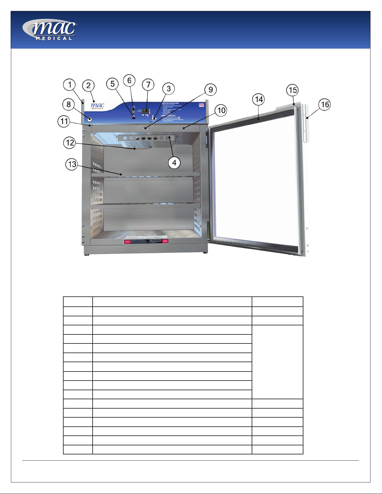
Main features of a Typical Warming Cabinet
(Single Chamber Cabinet shown here)
Instruction Manual
Fig. 5: Main Elements of a Warming Cabinet
This list shows the main elements of a warming cabinet. For a list of replacement parts with their part numbers
and quantities, see”Replacement Parts - General” on page 25 and “Replacement Parts - Header Assembly
and Electrical Drawer” on page 26.
Item # Description Qty
1 Header Assembly (24” and 30”) 1
2 Overlay (24” and 30”) D-Series 1
3 Key Housing
4 Air Box
5 USB cable plug
6 On/Off Switch
7 Display Board -Data (1 for each chamber)
8 Key Lock
9 Door Switch
10 Drawer Assembly (1 for each chamber)
11 Cam Lock Latch 1 per door
12 Probe J Type Thermocouple 1 per chamber
13 Adjustable Perforated Shelf As Required
14 Door (glass or steel) As Required
15 Cam Lock Plate 1 per door
16 Handle 1 per door
1 per chamber
MAN-001
9
www.macmedical.com
Instruction Manual
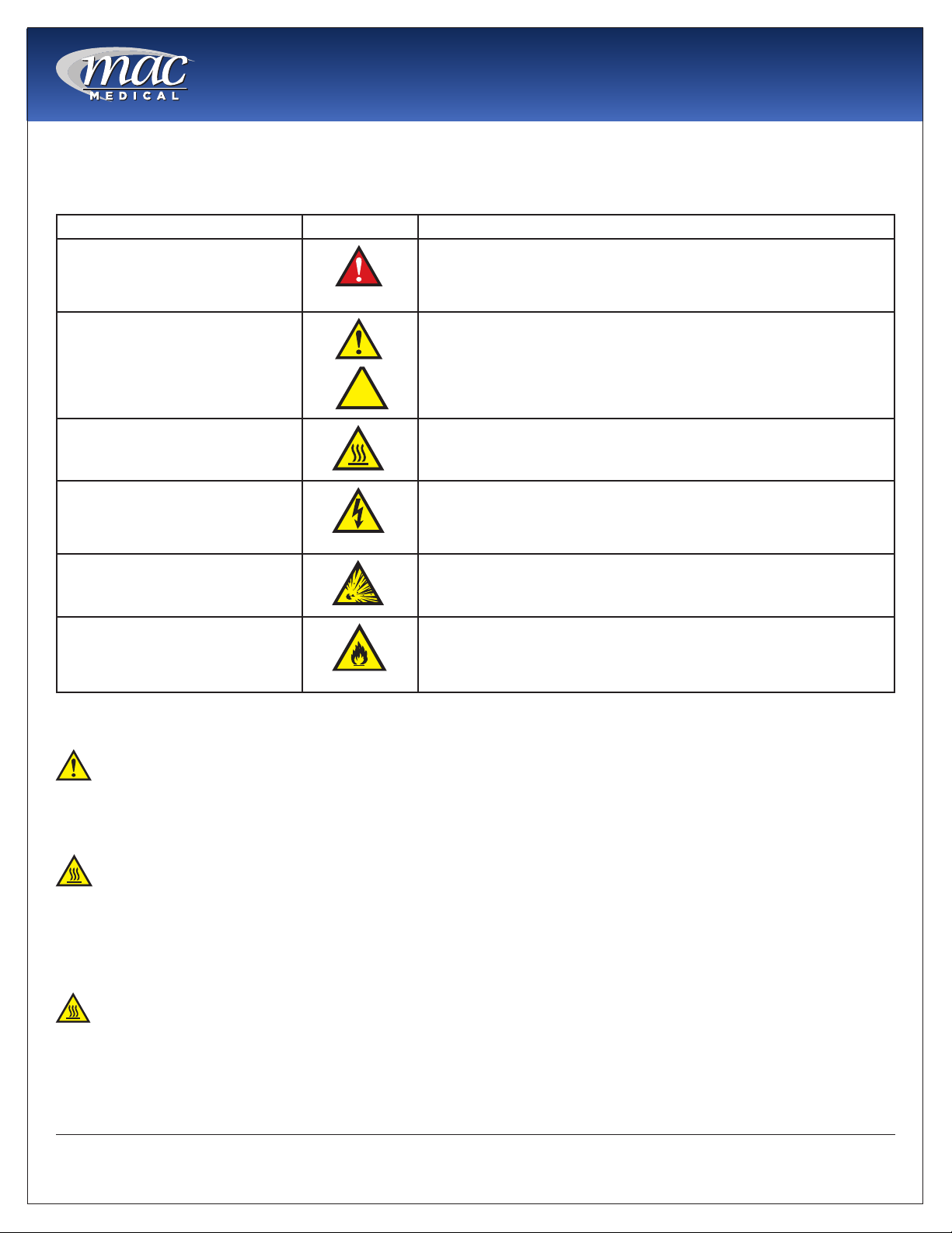
Warnings and Cautions
The following is a list identifying the various warning and caution icon used in this manual.
Icon Type Icon Description
Warnings
(Red triangle with an exclamation point) indicates the potential for
minor to severe injuries up to and including death to personnel.
Cautions
Burn Hazard Warnings
Electrical Warnings
Explosion Hazard
Fire Hazard
(Yellow triangle with an exclamation point) indicates the potential
minor injury to personnel and damage to equipment.
Note: The exclamation point will not be visible where only
equipment damage is present.
(Yellow triangle with radiating lines) indicates a potential burn injury
to personnel.
(Yellow triangle with a lightning bolt) indicates a possible shock
hazard is present. Severe shock hazards shall be a lightning bolt in a
red triangle.
(Yellow triangle with the explosion icon) indicates the equipment
should not be operated in areas where explosions could occur.
(Yellow triangle with the re icon) indicates the warning cabinet
should not be loaded with materials or liquids that are ammable or
use in the presence of ammable anesthetics or solvents.
The following is a list of safety precautions that must be observed when operating this equipment.
Warning - Injury Hazard
REPAIRS AND ADJUSTMENTS should be attempted only by experienced service representatives. Use of
unqualied persons to work on this equipment could result in personal injury or costly damage.
Warning - Burn Hazard
• Do NOT use in the presence of ammable anesthetics.
• Do NOT heat liquids in the presence of ammable solvents.
• Failure to observe this Warning can result in severe personal injury and even death.
Warning - Burn Hazard
• Do NOT exceed 150° F (65.56 C) for non-vented closures; (screw caps, crimp seals, plastic pouches, etc.).
Do not exceed pre-sterile solution manufacturer’s temperature requirements.
• Do NOT raise set temperature to increase rate of heating. Allow approximately 4-6 hours for solutions to
reach desired temperatures.
MAN-001
10
www.macmedical.com
Instruction Manual
• Do NOT use liquids on or inject into living tissue, unless actual liquid temperature has been measured
and is acceptable. Temperature of the warming cabinet’s contents may be hotter than the displayed
air temperature. For patient safety, in accordance with good medical practice, always check liquid
temperature prior to using.
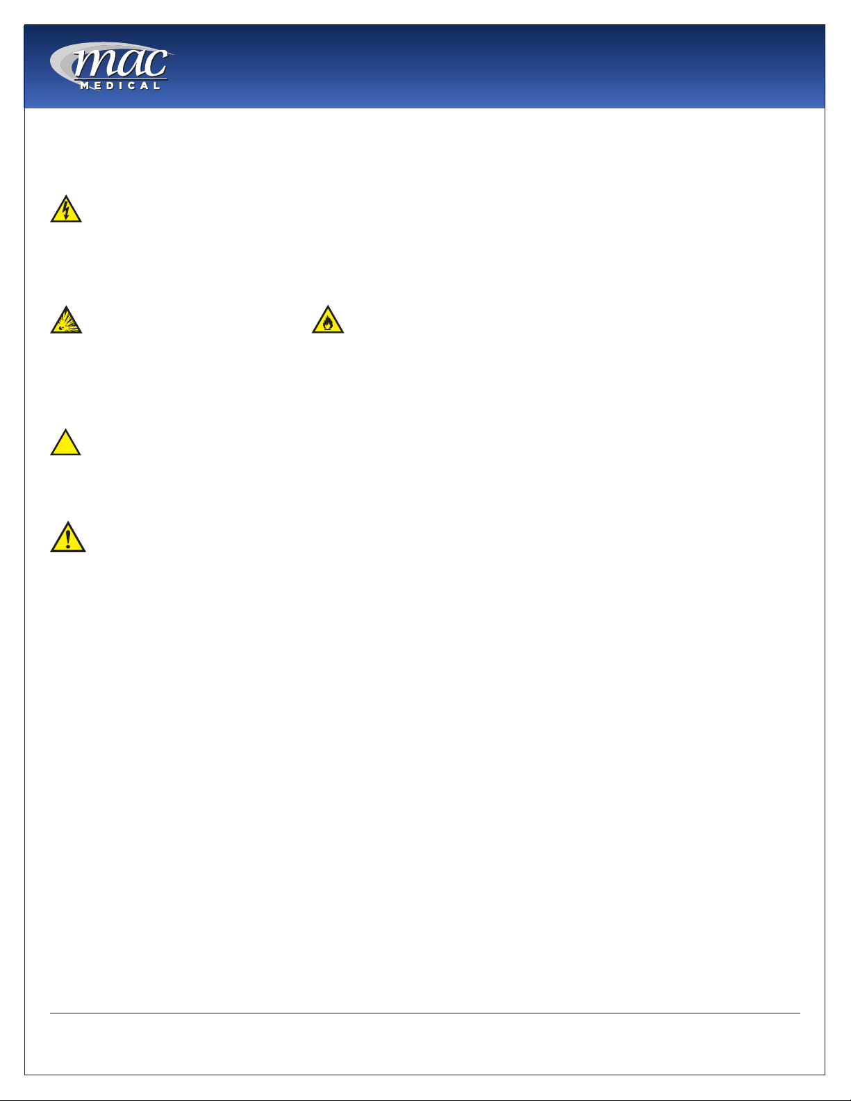
Warning - Electric Shock Hazard
Do NOT remove control tray. Contact a qualied service representative. Some of the troubleshooting
procedures can require access to live electrical circuitry. Dangerous accidental contact with line voltage is
possible. Only qualied service personnel should be allowed to perform these procedures.
Warning - Explosion Hazard or Fire Hazard
• Do not warm ammable materials or liquids.
• Do Not use in the presence of ammable anesthetics.
• Do Not heat liquids in the presence of ammable solvents.
Caution - Possible Equipment Damage
Some items are not acceptable in these warming cabinets. If in doubt as to whether an item can be safely
processed, have the facility supervisor contact the manufacturer of the item.
Caution: Repairs And Adjustments should only be attempted by experienced service personnel
who are fully acquainted with this equipment. Use of unqualied or inexperienced personnel to work on the
equipment, or the installation of unauthorized parts, could result in serious personal injury, or result in costly
damage. Always unplug power cord from power source before attempting any repairs or servicing of this
equipment.
Special User Attention
Prior to use, all personnel who will operate the Warming Cabinet must be instructed in the correct usage and
operation. All personnel who will use the Warming Cabinet should be aware that sensible care must be
exercised to maintain patient safety and to keep the Warming Cabinet performing at peak efciency.
Intended Use Notice
This product is intended to be used by medical personnel for the purpose of providing heated storage of
blankets, sterile water and saline solutions used in the care of patients in surgery, recovery, OB/GYN, ICU,
ER and trauma areas in healthcare facilities where al operators are instructed on the usage, limitations and
hazards. No other use is authorized or recommended.
This product is to be used strictly for the purpose for which it was designed. Using this product in a manner
not specied by MAC Medical, Inc. can void the protection provided by the equipment manufacturer. MAC
Medical, Inc. disclaims all liability for the consequences of this product being used for other than what it was
designed for. Product modication or misuse can be dangerous. MAC Medical, Inc. disclaims all liability for
the consequences of product alterations or modications, as well as for the consequence that can result
from the combination of this product with other products, whether supplied by MAC Medical, Inc. or by other
manufacturers, unless such a combination has been specically endorsed, in writing, by MAC Medical, Inc.
MAN-001
11
www.macmedical.com

Instruction Manual
Unpacking Instructions
Receiving Requirements
The customer is responsible for making sure the
loading dock at their facility can accommodate a
shipping carton approximately 70” inches (1.778 m)
long and 40” (1.016m) inches wide.
The customer must also provide transportation
equipment (forklift, etc) for a carton weighing
approximately 500 lbs (227 kg).
Inspection
1. Receiving area must meet all State and Local
regulations prior to unpacking.
2. Customer must inspect carton both before and
after unpacking to determine if any items were
damaged during shipping.
A. All damaged items must be listed on the Bill of
Lading.
B. The serial number and model number shown
on the carton label must match the numbers
on the Bill of Lading and the Invoice.
3. Customer is responsible for the proper disposal of
all packing materials. The disposal of these items
must meet all State and Local regulations.
plastic protective wrapping around the
Warming Cabinet. These items can scratch
the protective coating on the stainless steel
allowing the surface to rust.
9. The Warming Cabinet is now ready for use.
10. Discard shipping and packing materials in
compliance with local and state regulations.
11. Warmers, when not in use, must NOT be doublestacked while in storage. Warmers, while still in
shipping cartons, must not be double-stacked
when not in use.
Unpacking the Warming Cabinet
Retain all shipping materials until warming cabinet is
completely unpacked and inspected for damage.
1. Remove metal bands holding the bottom and
top of the shipping carton together.
2. Remove all metal staples holding the top and
bottom of the carton to its sides.
3. Remove the top of the carton.
4. Remove metal staples making the aps around
the top edge of the carton.
5. Remove metal staples attaching the sides of the
carton to the bottom of the carton.
6. Remove the sides of the carton by lifting them
straight up from the bottom tray.
7. Lift Warmer straight up from bottom tray of the
shipping carton and remove it.
8. Remove all protective packing material.
A.
Caution: DO NOT use a box cutter
or any other cutting utensil to remove the
Fig. 6: Warming Cabinet in Shipping Container
MAN-001
12
www.macmedical.com

Installing D-Series Warming Cabinets
environmental Conditions
This unit is intended for use in a stable ambient
environment, with an ideal temperature of 72° F
(22.22° C) or less. The unit should never be used
directly next to any appliance that may produce
heat, such as an autoclave.
During Transport and Storage (in original packaging
materials) -
• Ambient Temperature: -40° - 159°F (-40° - 70°C)
• Relative Air Pressure: 10% - 100%, including
condensation
• Air Pressure: 500 hPa (14 inHg - 31.3 inHg)
During Use - for Dry Locations
• Ambient Temperature: 60° - 85°F (15° - 30°C)
• Relative Air Moisture: 30% - 60% non-condensing
• Air Pressure: 700 hPa - 1060 hPa (20.7 inHg - 31.3
inHg)
Instruction Manual
1. Carefully uncrate the D-Series Warming Cabinet.
2. Inspect for any damage. If there is damage,
please contact MAC Medical, Inc. at (1-877-828-
9975).
3. Check your 120V, 60 Hz, Single Phase 15 AMP
GFIC Protected electrical outlet or 220V, 60 Hz,
Single Phase, 7 AMP GFIC Protected electrical
outlet. Be sure the outlet is safely accessible and
in proper working condition.
4. Plug the 3-prong electrical plug into the 120VAC,
60Hz, 15 AMP, GFIC Protected Outlet or a 220
VAC, 60Hz, Single Phase, 7 AMP GFIC protected
electrical outlet. Make sure the electrical outlet is
safely accessible and in proper working condition.
5. Place Warming Cabinet on a solid, level platform
where external movement will not interfere with
loose contents used by the warmer.
6. Make sure the shelving is correctly located as
desired and level. If not, adjust their height (see
“Adjusting the Shelves” on page 19).
7. Before use, remove any items that have been
stored in the cabinet.
Installation
Before starting the installation, review the local
electric codes including the Occupational Health
and Safety Act for any requirements pertaining to the
proper installation of this equipment.
Contact your MAC Medical representative for seismic
calculations and tie-down hardware, if applicable.
Testing before Using
All warming cabinets have been calibrated and
tested before leaving the factory. There is no need
for the user to do additional testing after installation
prior to use.
After six month of use, it is recommended that the
user test the warming cabinet for temperature
accuracy. See “Semi-Annual Checklist” on page
24.
MAN-001
13
www.macmedical.com
Instruction Manual
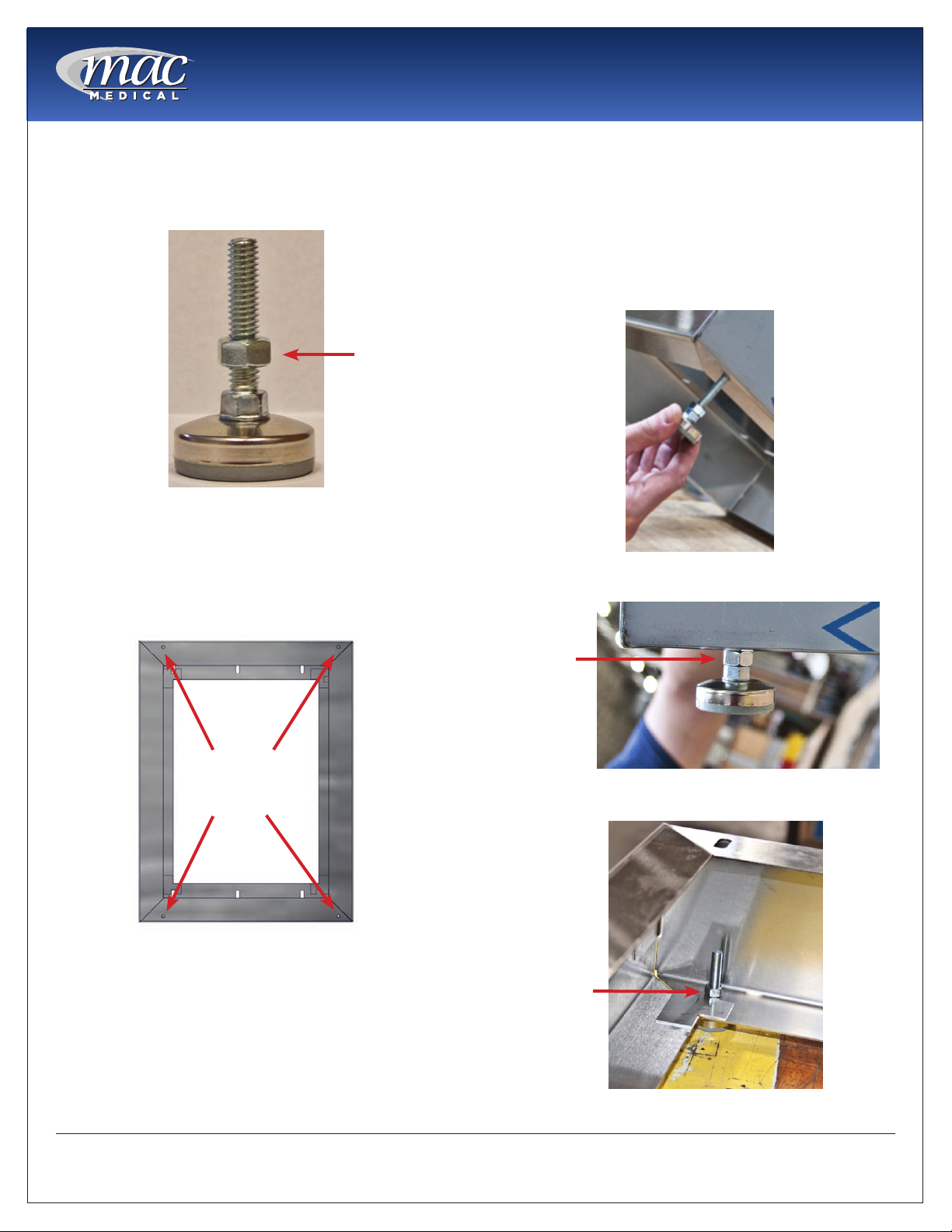
Installing Warming Cabinet leg levelers
Warming Cabinets are shipped with 4 Leg Levelers
which must installed by the customer (Fig. 7).
Jamb Nut
Fig. 7: Leg Leveler
The Warming Cabinet base has 4 holes into which
the Leg Levelers can be installed (Fig. 8).
Working with at least two people, carefully tilt the
Warming Cabinet back slightly and insert the 4 Leg
Levelers up into the 4 provided holes (Fig. 9).
IMPORTAnT: The Jamb Nut must go on the outside of
the Cabinet Base, not the inside. Fig.10 shows a Leg
Leveler correctly installed with the Jamb Nut outside
the base. Fig. 11 shows the Leg Leveler incorrectly
installed with the Jamb Nut inside the base.
Fig. 9: Insert Leg Leveler into base
Holes for
Leg Levelers
Fig. 8: Holes in Cabinet base
Jamb Nut
Fig. 10: Leg Leveler - Correct installation
Jamb Nut
Fig. 11: Leg Leveler - Incorrect installation
MAN-001
14
www.macmedical.com
Instruction Manual
2
5
2
3
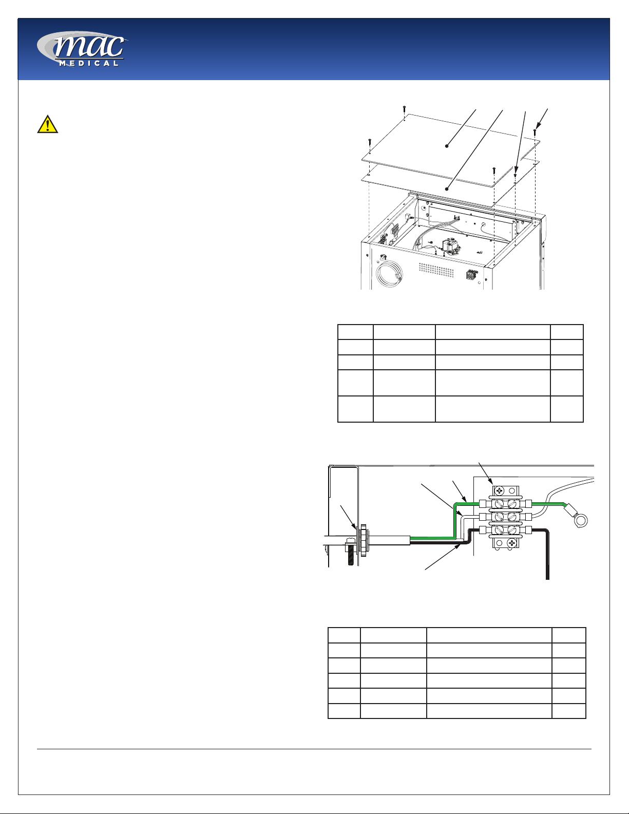
Optional Direct Wiring Using facility Power Supply
NOTE: The following procedure must be performed
by a qualied electrical technician to avoid personal
injury or damage to the unit.
Warming Cabinets can be wired directly into the
facility’s wiring by following these steps:
1. Remove four 8 X 1-5/8” self tapping screws and lift
off the Top Outer Panel. See Fig. 7.
2. Remove two 8 X 1/2” self tapping screws and lift off
the Top Inner Panel. See Fig. 7.
3. Loosen the 3/8” straight-thru connector (See Figure
4, Item 1) and disconnect wiring from terminal
board (Figure 4, Item 5) and from Fig. 8, Items 2, 3, 4.
4. Remove existing power cable (See Figure 4, Items
2, 3, and 4) from terminal block and pull out of
Warming Cabinet through 3/8” connector (See Fig.
8, Item 1).
5. Feed facility wiring cable back through the 3/8”
connector (See Fig. 8, Item 1) in the back of the
cabinet and wire onto terminal board as shown in
Fig. 8. Tighten the 3/8” to securely hold the facility
wiring in place.
6. On the terminal board, The green wire (Item 4)
connects with the green ground wire.
7. The white wire (Item 3) connects opposite with the
white wire, or neutral wire, on the terminal board.
8. The black wire (Item 2) connects opposite of the
black or positive wire on the terminal board.
9. Re-install the Inside Top Panel using two 8 X 1/2” selftapping screws. See Fig. 7.
10. Re-install the Outside Top Panel using four 8 X 1-5/8”
self-tapping screws. See Fig. 7.
11. Carefully slide the unit into its permanent location.
1
Fig. 12: Remove Top Covers
Item P/n Description Qty
1 SMW0027 Outside Top Panel 1
2 SMW0028 Inside Top Panel 1
3 H0012-01 Screw, Self-Tapping, 8
X 1/2”
4 H0012-02 Screw, Self-Tapping, 8
X 1-5/8”
3
4
1
4
2
4
MAN-001
Fig. 13: Unwiring Terminal Block
Item P/n Description Qty
1 W0140 Connector, Straight, 3/8” 1
2 W0077 Wire, Black, Positive 1
3 W0077 Wire, White, Neutral 1
4 W0077 Wire, Green, Ground 1
5 W0005 Terminal Strip, 3-Position 1
15
www.macmedical.com
 Loading...