

Mac Medical SWC243024, SWC243036, SWC242436, SWC182464, SWC242464 Installation Operation & Maintenance
...
INSTRUCTION MANUAL
Installation - Operation - Maintenance
MAN-001 Rev J
D-Series Warming Cabinets
OSHPD
R
C
Read and understand all of the instructions and safety
information in this manual before operating this product.
© 2018 MAC Medical, Inc.
Pre-Approved
10/2018

Instruction Manual
TAble Of COnTenTS
Summary 3
D-Series Warming Cabinet Models
Interior Dimensions, Cubic Foot Capacity, Approximate Capacity
General Specications
Main Features of a Typical Warming Cabinet
Warnings and Cautions
Unpacking Instructions
Receiving Requirements
Installing D-Series Warming Cabinets
Environmental Conditions
Installation
Testing before Using
Installing Warming Cabinet Leg Levelers
Optional Direct Wiring Using Facility Power Supply
Basic Operation
Recommended Settings
Loading Contents in Cabinet
In Case of Power Failure
Explanation of the Controls
Operation of Display Panel
Installing the Shelves
Adjusting the Shelves
Installing and Adjusting Optional Roller Basket Shelves
Unloading the Warming Cabinet
Retrieval of Recorded Temperatures
Turning Off the Warming Cabinet
Troubleshooting
Overheat Alarm (HI) Condition
Cleaning Stainless Steel Warming Cabinets
Preventative Maintenance Checklist
Replacement Parts - General
Replacement Parts - Header Assembly and Electrical Drawer
Optional Cabinet Bases, Mobile Bases and Mobile Stands
Steel or Glass Door Hinge Reversal
Remove Panels
Remove Header Assembly Box & Relocate Cam Lock
Purchase Parts Needed for Cam Lock Reversal
Glass Door Hinge Reversal and Re-installation
Steel Door Hinge Reversal and Re-installation
Purchase Parts Needed for Door Hinge Reversal
Wiring Diagram - Single Chamber Warmers
Wiring Diagram - Dual Chamber Warmers
Wiring Diagram - Triple Chamber Warmers
Index
41
Limited Lifetime Warranty
7
9
11
11
12
12
15
18
18
21
28
44
4
5
8
12
12
13
14
15
15
15
16
17
19
20
20
20
21
22
23
24
25
27
28
29
29
32
35
35
38
39
40
MAN-001
2
www.macmedical.com

Summary
Instruction Manual
DeSCRIPTIOn Of PRODUCT
This manual covers the D-Series (Data
Logging) blanket and uid warming cabinets,
manufactured for commercial use only. These
include the single, dual and triple chamber units.
PURPOSe Of THIS MAnUAl
This manual is to provide the user instructions in
the installation, operation and maintenance of
the D-Series warming cabinets.
This manual also contains general
specications, warnings and cautions.
Indications for Use:
The MAC Medical Inc. Blanket and Solution Warming Cabinets are designed to store and warm blankets,
hospital linens, irrigation uids, and/or injection uids in accordance with recommended warming
temperatures and storage time guidelines provided by the manufacturers of such products.
MAN-001
3
www.macmedical.com
Instruction Manual
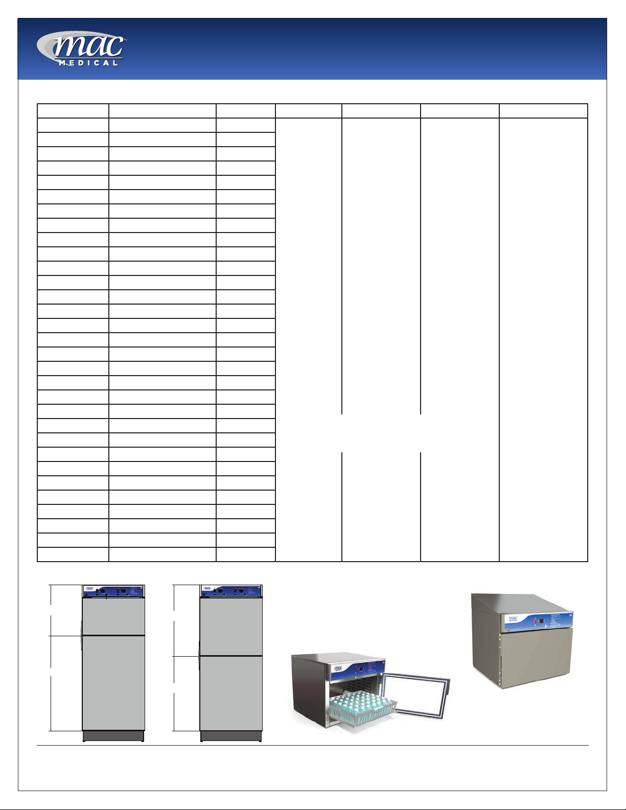
D-Series Warming Cabinet Models
Model # Overall Size Chambers Door Type Door Hinge base Style Other Options
SWC151822 17.25"D x 18"W x 22"H Single G=Glass Door
SWC182424 20.5"D x 24"W x 24.5"H Single
SWC242424 26.5”D x 24”W x 24.5”H Single
SWC183024 20.5"D x 30"W x 24.5"H Single
SWC243024 26.5"D x 30"W x 24.5"H Single
SWC182436 20.5”D x 24”W x 36”H Single
SWC183036 20.5"D x 30"W x 36"H Single
SWC242436 26.5”D x 24”W x 36”H Single
SWC243036 26.5"D x 30"W x 36"H Single
SWC182464 20.5"D x 24"W x 64.75"H Single
SWC242464 26.5"D x 24"W x 64.75"H Single
SWC183064 20.5"D x 30"W x 64.75"H Single
SWC243064 26.5"D x 30"W x 64.75"H Single
SWC182474 20.5”D x 24”W x 74.5”H Single
SWC183074 20.5"D x 30"W x 74.5"H Single
SWC242474 26.5”D x 24”W x 74.5”H Single
SWC243074 26.5"D x 30"W x 74.5"H Single
DWC182464T* 20.5"D x 24"W x 64.75"H Dual
DWC242464T* 26.5"D x 24"W x 64.75"H Dual
DWC183064T* 20.5"D x 30"W x 64.75"H Dual
DWC243064T* 26.5"D x 30"W x 64.75"H Dual
DWC182474T* 20.5"D x 24"W x 74.5"H Dual
DWC242474T* 26.5"D x 24"W x 74.5"H Dual
DWC183074T* 20.5"D x 30"W x 74.5"H Dual
DWC243074T* 26.5"D x 30"W x 74.5"H Dual
DWC182474E** 20.5”D x 24”W x 74.5”H Dual
DWC183074E** 20.5"D x 30"W x 74.5"H Dual
DWC242474E** 26.5”D x 24”W x 74.5”H Dual
DWC243074E** 26.5"D x 30"W x 74.5"H Dual
TWC183078 20.5"D x 30"W x 78.75"H Triple
TWC243078 26.5"D x 30"W x 78.75"H Triple
Blank=Stainless
Steel Door
(Standard)
ţ Only available for Triple Chamber Unit
ţţ Only available for Dual and Triple Chamber Units
LH=Left Hinge
Blank = Right
Hinge (Standard)
2B = 2” Base
4B = 4” Base
6B = 6” Base
NB = No Base
MB = Mobile Base
220 = 220/240V
Power Supply
C = Celsius
R1 = Recessed
Unit with Insulation
Wrap, no Top Panel,
no Side Panels and
no Trim Kit.
R2 = Recessed Unit
with Top Panel, Side
Panels, and Trim Kit.
SB = Seismic Braces
WB = Roll Out
Basket
P = Pass Through
Chamber
IV = IV/Injection
Fluids
ST = Sloped Top
EL = Electronic
Keypad lock
ţ DL = Intermediate
Chamber Door Lock
(triple chamber
units)
ţţ LDL = Lower
Chamber Door
Lock (dual/triple
chamber units)
* = Chambers in Thirds ** = Equal Chambers
1/3
2/3
1/2
1/2
MAN-001
Sloped Top
Roll Out basket
4
www.macmedical.com

Interior Dimensions, Cubic foot Capacity, Approximate Capacity
Instruction Manual
Model # Upper or single
Chamber
(h x w x d) in
inches
SWC151822 14.0 x 14.0 x 11.63 n/a n/a/ 1.30 n/a n/a 5 - 6 blankets, 8 bottles
SWC182424 15.25 x 20.0 x 17.0 n/a n/a 3.0 n/a n/a 9 blankets, 8 bottles
SWC242424 15.25 x 20.0 x 23.0 n/a n/a 4.06 n/a n/a 9 blankets, 12 bottles
SWC183024 15.25 x 26.0 x 17.0 n/a n/a 3.9 n/a n/a 18 blankets, 8 bottles
SWC243024 15,25 x 26.0 x 23.0 n/a n/a 5.27 n/a n/a 18 blankets, 20 bottles
SWC242436 36.0 x 20.0 x 23.0 n/a n/a 6.7 n/a n/a 16 blankets, 25 bottles
SWC182436 25.0 x 20.0 x 17.0 n/a n/a 5.0 n/a n/a 16 blankets, 20 bottles
SWC183036 25.0 x 26.0 x17.0 n/a n/a 6.39 n/a n/a 32 blankets, 36 bottles
SWC243036 25.0 x 26.0 x 23.0 n/a n/a 8.65 n/a n/a 32 blankets, 40 bottles
SWC182464 49.5 x 20.0 x 17.0 n/a n/a 9.74 n/a n/a 32 blankets, 48 bottles
SWC242464 51.0 x 20.0 x 23.0 n/a n/a 13.60 n/a n/a 80 blankets, 120 bottles
SWC183064 51.0 x 26.0 x 17.0 n/a n/a 13.05 n/a n/a 66 blankets, 72 bottles
SWC243064 51.0 x 26.0 x 23.0 n/a n/a 17.65 n/a n/a 80 blankets, 120 bottles
SWC182474 61.0 x 20.0 x 17.0 n/a n/a 12.00 n/a n/a 32 blankets, 60 bottles
SWC183074 61.0 x 26.0 x 17.0 n/a n/a 15.60 n/a n/a 80 blankets, 72 bottles
SWC242474 61.0 x 20.0 x 23.0 n/a n/a 16.24 n/a n/a 80 blankets, 120 bottles
SWC243074 61.0 x 26.0 x 23.0 n/a n/a 21.1 n/a n/a 80 blankets, 120 bottles
DWC182464T* 13.5 x 20.0 x 17.0 n/a 24.5 x 20.0 x
DWC242464T* 13.5 x 20.0 x 23.0 n/a 24.5 x 20.0 x
DWC183064T* 13.5 x 26.0 x 17.0 n/a 24.5 x 26.0
DWC243064T* 13.5 x 26.0 x 23.0 n/a 24.5 x 26.0 x
DWC182474T* 15.25 x 20.0 x 17.0 n/a 34.5 x 20.0 x
DWC242474T* 15.25 x 20.0 x 23.0 n/a 34.5 x 20.0 x
DWC183074T* 15.25 x 26.0 x 17.0 n/a 34.5 x 26.0 x
DWC243074T* 15.25 x 26.0 x 23.0 n/a 34.5 x 26.0 x
DWC182474E** 25.0 x 20.0 x 17.0 n/a 26.0 x 20.0 x
DWC183074E** 25.0 x 26.0 x 17.0 n/a 26.0 x 26.0 x
DWC242474E** 25.0 x 20.0 x 23.0 n/a 26.0 x 20.0 x
DWC243074E** 25.0 x 26.0 x 23.0 n/a 26.0 x 26.0 x
TWC183078 11.25 x 26.0 x 17.0 10.75 x 26.0
TWC243078 11.25 x 26.0 x 23.0 10.75 x 26.0
Middle
Chamber
(h x w x d)
in inches
x 17.0
x 23.0
lower
Chamber
(h x w x d)
in inches
17.0
23.0
x17.0
23.0
17.0
23.0
17.0
23.0
17.0
17.0
23.0
23.0
18.5 x 26.0
x 17
18.5 x 26.0 x
23.0
Cubic foot
Capacity
Upper or single
Chamber
2.65 n/a 4.82 26 blankets, 36 bottles
3.59 n/a 6.52 52 blankets, 80 bottles
3.45 n/a 6.27 50 blankets, 54 bottles
4.67 n/a 8.48 52 blankets, 96 bottles
2.65 n/a 6.79 32 blankets, 48 bottles
4.06 n/a 9.18 52 blankets, 80 bottles
3.45 n/a 8.82 52 blankets, 72 bottles
5.28 n/a 11.93 52 blankets, 120 bottles
4.97 n/a 5.24 44 blankets, 48 bottles
6.39 n/a 6.65 64 blankets, 72 bottles
6.65 n/a 6.99 64 blankets, 80 bottles
8.65 n/a 8.99 64 blankets, 120 bottles
2.88 2.75 4.73 62 blankets, 54 bottles
3.89 3.72 6.4 62 blankets, 90 bottles
Cubic foot
Capacity
Middle
Chamber
Cubic foot
Capacity
lower
Chamber
Approximate
Capacity
(blankets or 1 liter
solution bottles)
MAN-001
5
www.macmedical.com
Instruction Manual
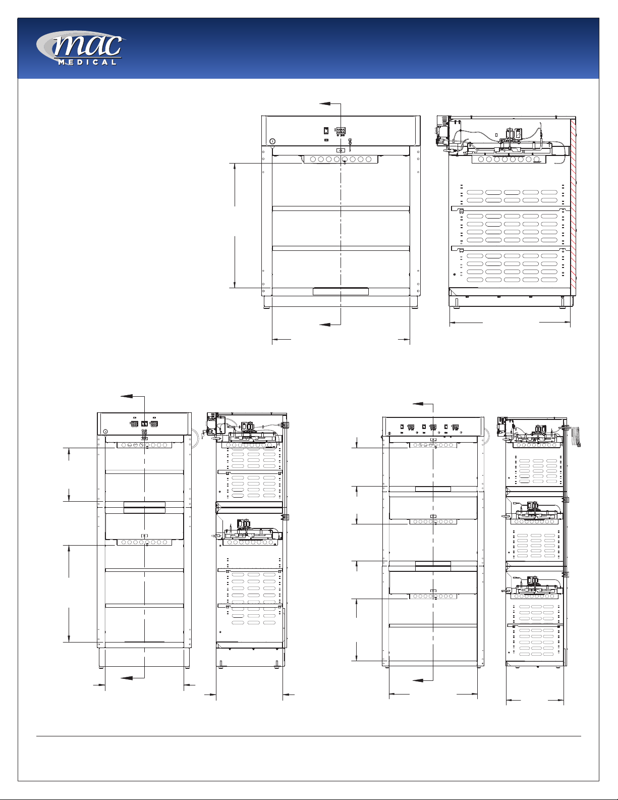
Usable Chamber Space
The usable chamber space of the
single, dual and triple cabinets
is slightly different from the
height, width, and depth interior
dimensions in the table on the
previous page.
Note that the usable chamber
inner height is measured from
the bottom of the air box to the
bottom of the chamber.
(In these views, the doors were
removed for clarity.)
USABLE
INNER HEIGHT
DIMENSION
A
A
CHAMBER WIDTH DIMENSION
Fig. 1: Single Chamber Unit Usable Space
CHAMBER DEPTH
DIMENSION
SECTION A-A
A
USEABLE
INNER HEIGHT
DIMENSION
USEABLE
INNER HEIGHT
DIMENSION
A
CHAMBER
WIDTH
DIMENSION.
Fig. 2: Dual Chamber Unit Usable Space
SECTION A-A
CHAMBER
DEPTH
DIMENSION.
A
USEABLE
INNER HEIGHT
DIMENSION
USEABLE
INNER HEIGHT
DIMENSION
USEABLE
INNER HEIGHT
DIMENSION
A
CHAMBER
WIDTH
DIMENSION
Fig. 3: Triple Chamber Unit Usable Space
SECTION A-A
CHAMBER
DEPTH
DIMENSION
MAN-001
6
www.macmedical.com
Instruction Manual
General Specications
Cabinet Construction and Material
• 300 Stainless Steel (all panels, header and doors) Double walled construction with insulation. Doors are
double pan stainless steel.
• Fully insulated to provide uniform heating
• Optional Glass door are double paned tempered glass framed with aluminum.
• Doors are fully gasketed and hinged on right side or optionally on the left side.
Factory Presets
• All units are preset to measure temperature in Fahrenheit (unless the unit was specically ordered to be
preset for Celsius.)
Power Requirements
• 120VAC, 60Hz, Single Phase, 15 AMP,
Ground Fault Interrupter Circuit (GFIC)
protected electrical outlet, or 220 VAC,
60Hz, Single Phase, 7 AMP, GFIC protected
electrical outlet (by others) installed
per local building codes and provides
protective grounding.
• Cabinets are supplied with a 7 foot (2.3m)
long, 14-3 SJT power cord with a 120V
(NEMA 15P) hospital grade plug. For multichambered units, ON/OFF switches are
supplied for each chamber.
• All individual electronic components are
Underwriter’s Laboratory (UL) approved
and recognized.
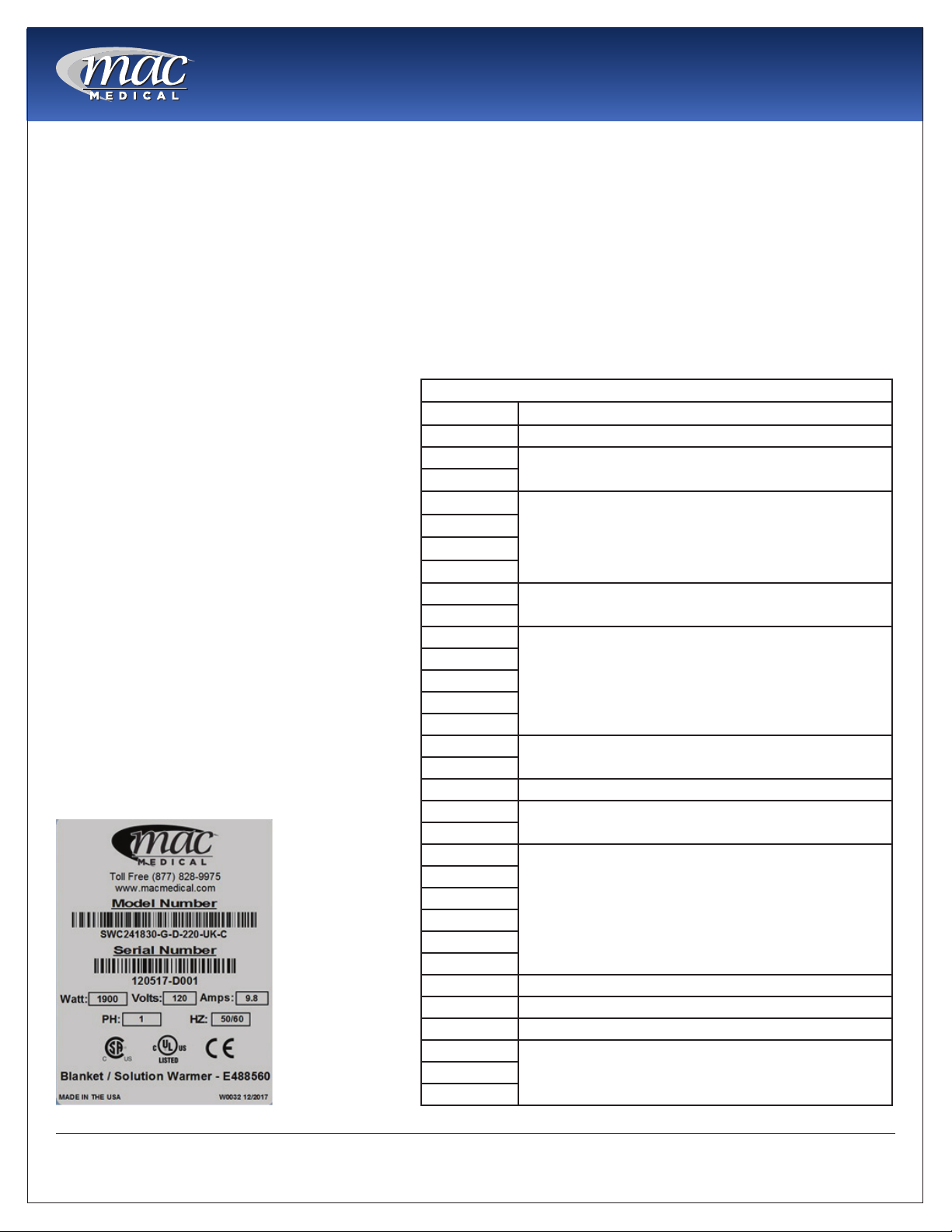
Power Specications are located on the unit
identication rating tag (see Fig. 4) which is
permanently attached on the inside of the
door or on the back of the upper chamber.
Model # Description
SWC151822 120V, 2.08 Amp, 50/60Hz, .25 kWh (Avg.), 853 BTU/hr (Avg.)
SWC182424
SWC182436
SWC242424
SWC242436
SWC243024
SWC243036
SWC183024
SWC183036
SWC182464
SWC182474
SWC183074
SWC242474
SWC243074
SWC242464
SWC243064
SWC183064 120V, 6.3 Amp, 50/60 Hz, .41 kWh (Avg.), 1400 BTU/hr (Avg.)
DWC183064T
DWC242464T
DWC182464T
DWC182474E
DWC182474T
DWC243064T
DWC242474E
DWC242474T
DWC183074T 120V, 8.3 Amp, 50/60 Hz, .82 kWh (Avg.), 2047 BTU/hr (Avg.)
DWC243074T 120V, 12.5 Amp, 50/60 Hz, .90 kWh (Avg.), 3071 BTU/hr (Avg.)
DWC183074E 120V, 11.4 Amp, 50/60 Hz, .82 kWh (Avg.), 2798 BTU/hr (Avg.)
DWC243074E
TWC243078
Electrical Specications by Model
120V, 2.9 Amp, 50/60 Hz, .23 kWh (Avg.), 785 BTU/hr (Avg.)
120V, 6.3 Amp, 50/60 Hz, .45 kWh (Avg.), 1535 BTU/hr (Avg.)
120V, 5.7 Amp, 50/60 Hz, .45 kWh (Avg.), 1535 BTU/hr (Avg.)
120V, 6.5 Amp, 50/60 Hz, .47 kWh (Avg.), 1604 BTU/hr (Avg.)
120V, 6.5 Amp, 50/60 Hz, .41 kWh (Avg.), 1604 BTU/hr (Avg.)
120V, 8.3 Amp, 50/60 Hz, .60 kWh (Avg.), 2047 BTU/hr (Avg.)
120V, 8.9 Amp, 50/60 Hz, .65 kWh (Avg.), 2218 BTU/hr (Avg.)
120V, 12.9 Amp, 50/60 Hz, .90 kWh (Avg.), 3071 BTU/hr (Avg.)TWC183078
Fig. 4: Power Specication Label
MAN-001
7
www.macmedical.com

Instruction Manual
MAC Medical Warming Cabinet handles are equipped with CuVerro® bactericidal copper surfaces.
° This product is made from a copper surface that continuously kills bacteria* left behind by dirty
hands, killing more than 99.9% of bacteria* within 2 hours.
Laboratory testing has shown that when cleaned regularly this surface:
° Kills more than 99.9% of bacteria* within 2 hours, and continues to kill 99% of bacteria* even after
repeated contamination.
° Delivers continuous and ongoing antibacterial* action, remaining effective in killing greater than
99.9% of bacteria* within 2 hours.
° Helps inhibit buildup and growth of bacteria* within 2 hours of exposure between routine cleaning
and sanitizing steps.
° Kills greater than 99.9% of Gram-negative and Gram-positive bacteria* within 2 hours of exposure.
° Continuously reduces bacterial* contamination, achieving 99.9% reductin within 2 hours of exposure.
* Laboratory testing shows that, when cleaned regulary, CuVerro surfaces kill greater than 99.9% of the following bacteria
within 2 hours of exposure: Methicillin-Resistant Staphylococcus aureus, Staphylococcus aureus, Enterobacter aerogenes,
Pseudomonas aeruginosa, E. coli O157:H7, and Vancomycin-Resistant Enterococcus faecalis (VRE).
The use of CuVerro® bactericidal copper products is a supplement to and not a substitute for standard infection control
practices; users must continue to follow all current infection control practices, including those practices related to cleaning
and disinfection of environmental surfaces. This surface has been shown to reduce microbial contamination, but it does not
necessarily prevent cross contamination.
CuVerro® is a registered trademark of GBC Metals, LLC and is used with permission.
EPA Company No. 92702-IL-1 EPA Registration No. 92701
MAN-001
8
www.macmedical.com
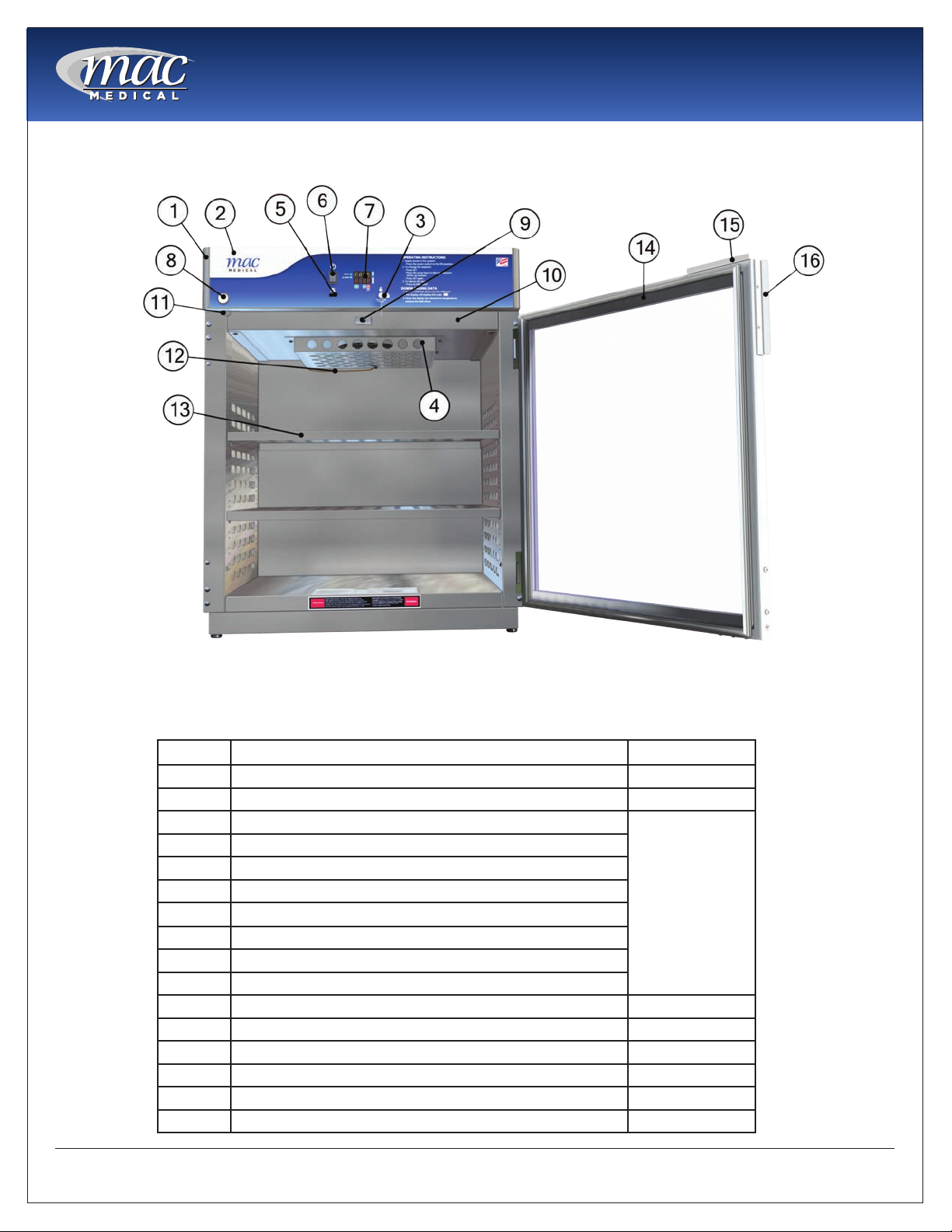
Main features of a Typical Warming Cabinet
(Single Chamber Cabinet shown here)
Instruction Manual
Fig. 5: Main Elements of a Warming Cabinet
This list shows the main elements of a warming cabinet. For a list of replacement parts with their part numbers
and quantities, see”Replacement Parts - General” on page 25 and “Replacement Parts - Header Assembly
and Electrical Drawer” on page 26.
Item # Description Qty
1 Header Assembly (24” and 30”) 1
2 Overlay (24” and 30”) D-Series 1
3 Key Housing
4 Air Box
5 USB cable plug
6 On/Off Switch
7 Display Board -Data (1 for each chamber)
8 Key Lock
9 Door Switch
10 Drawer Assembly (1 for each chamber)
11 Cam Lock Latch 1 per door
12 Probe J Type Thermocouple 1 per chamber
13 Adjustable Perforated Shelf As Required
14 Door (glass or steel) As Required
15 Cam Lock Plate 1 per door
16 Handle 1 per door
1 per chamber
MAN-001
9
www.macmedical.com
Instruction Manual
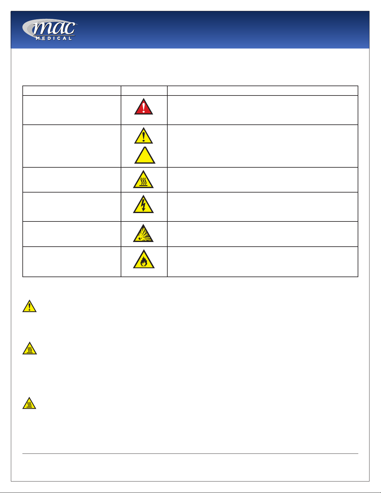
Warnings and Cautions
The following is a list identifying the various warning and caution icon used in this manual.
Icon Type Icon Description
Warnings
(Red triangle with an exclamation point) indicates the potential for
minor to severe injuries up to and including death to personnel.
Cautions
Burn Hazard Warnings
Electrical Warnings
Explosion Hazard
Fire Hazard
(Yellow triangle with an exclamation point) indicates the potential
minor injury to personnel and damage to equipment.
Note: The exclamation point will not be visible where only
equipment damage is present.
(Yellow triangle with radiating lines) indicates a potential burn injury
to personnel.
(Yellow triangle with a lightning bolt) indicates a possible shock
hazard is present. Severe shock hazards shall be a lightning bolt in a
red triangle.
(Yellow triangle with the explosion icon) indicates the equipment
should not be operated in areas where explosions could occur.
(Yellow triangle with the re icon) indicates the warning cabinet
should not be loaded with materials or liquids that are ammable or
use in the presence of ammable anesthetics or solvents.
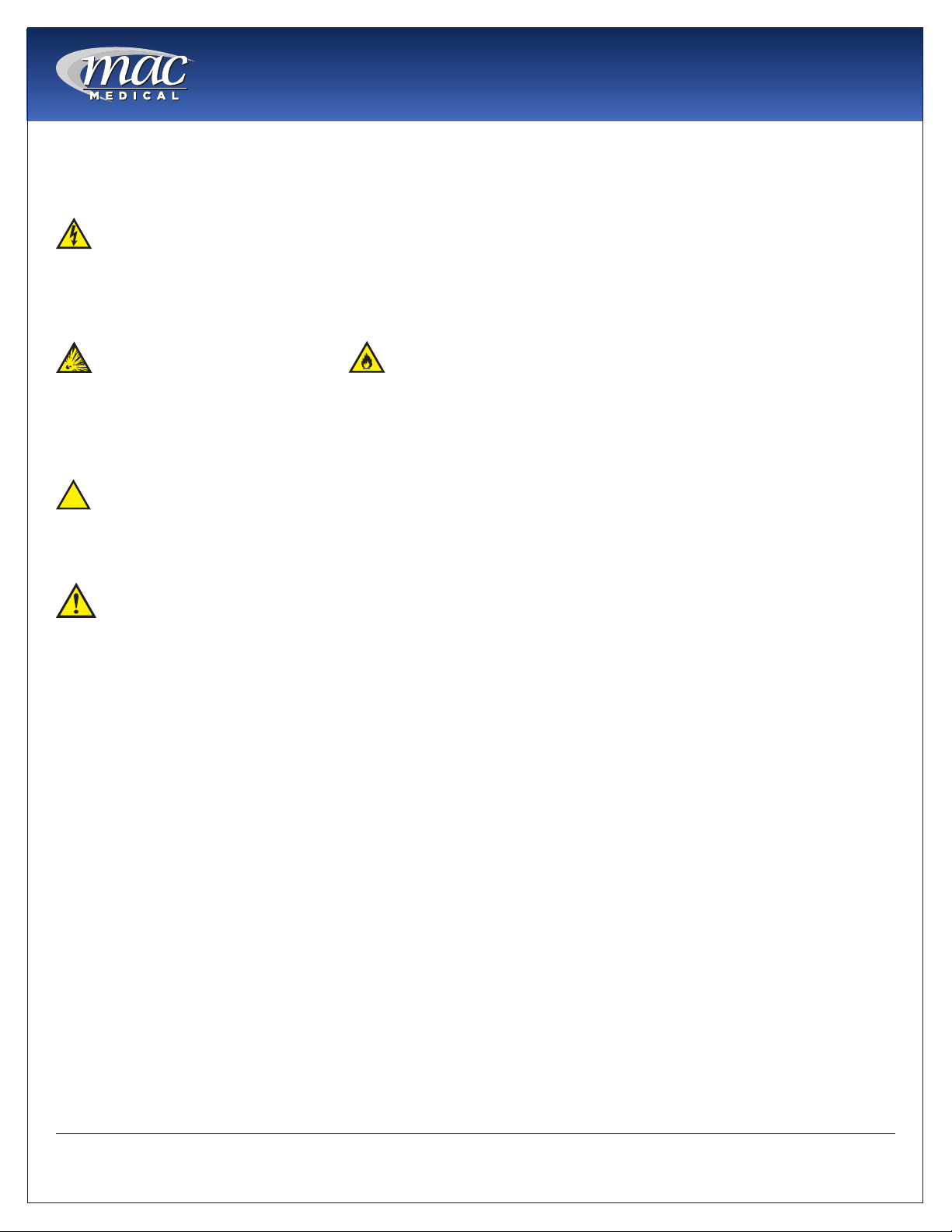
The following is a list of safety precautions that must be observed when operating this equipment.
Warning - Injury Hazard
REPAIRS AND ADJUSTMENTS should be attempted only by experienced service representatives. Use of
unqualied persons to work on this equipment could result in personal injury or costly damage.
Warning - Burn Hazard
• Do NOT use in the presence of ammable anesthetics.
• Do NOT heat liquids in the presence of ammable solvents.
• Failure to observe this Warning can result in severe personal injury and even death.
Warning - Burn Hazard
• Do NOT exceed 150° F (65.56 C) for non-vented closures; (screw caps, crimp seals, plastic pouches, etc.).
Do not exceed pre-sterile solution manufacturer’s temperature requirements.
• Do NOT raise set temperature to increase rate of heating. Allow approximately 4-6 hours for solutions to
reach desired temperatures.
MAN-001
10
www.macmedical.com
Instruction Manual
• Do NOT use liquids on or inject into living tissue, unless actual liquid temperature has been measured
and is acceptable. Temperature of the warming cabinet’s contents may be hotter than the displayed
air temperature. For patient safety, in accordance with good medical practice, always check liquid
temperature prior to using.
Warning - Electric Shock Hazard
Do NOT remove control tray. Contact a qualied service representative. Some of the troubleshooting
procedures can require access to live electrical circuitry. Dangerous accidental contact with line voltage is
possible. Only qualied service personnel should be allowed to perform these procedures.
Warning - Explosion Hazard or Fire Hazard
• Do not warm ammable materials or liquids.
• Do Not use in the presence of ammable anesthetics.
• Do Not heat liquids in the presence of ammable solvents.
Caution - Possible Equipment Damage
Some items are not acceptable in these warming cabinets. If in doubt as to whether an item can be safely
processed, have the facility supervisor contact the manufacturer of the item.
Caution: Repairs And Adjustments should only be attempted by experienced service personnel
who are fully acquainted with this equipment. Use of unqualied or inexperienced personnel to work on the
equipment, or the installation of unauthorized parts, could result in serious personal injury, or result in costly
damage. Always unplug power cord from power source before attempting any repairs or servicing of this
equipment.
Special User Attention
Prior to use, all personnel who will operate the Warming Cabinet must be instructed in the correct usage and
operation. All personnel who will use the Warming Cabinet should be aware that sensible care must be
exercised to maintain patient safety and to keep the Warming Cabinet performing at peak efciency.
Intended Use Notice
This product is intended to be used by medical personnel for the purpose of providing heated storage of
blankets, sterile water and saline solutions used in the care of patients in surgery, recovery, OB/GYN, ICU,
ER and trauma areas in healthcare facilities where al operators are instructed on the usage, limitations and
hazards. No other use is authorized or recommended.
This product is to be used strictly for the purpose for which it was designed. Using this product in a manner
not specied by MAC Medical, Inc. can void the protection provided by the equipment manufacturer. MAC
Medical, Inc. disclaims all liability for the consequences of this product being used for other than what it was
designed for. Product modication or misuse can be dangerous. MAC Medical, Inc. disclaims all liability for
the consequences of product alterations or modications, as well as for the consequence that can result
from the combination of this product with other products, whether supplied by MAC Medical, Inc. or by other
manufacturers, unless such a combination has been specically endorsed, in writing, by MAC Medical, Inc.
MAN-001
11
www.macmedical.com

Instruction Manual
Unpacking Instructions
Receiving Requirements
The customer is responsible for making sure the
loading dock at their facility can accommodate a
shipping carton approximately 70” inches (1.778 m)
long and 40” (1.016m) inches wide.
The customer must also provide transportation
equipment (forklift, etc) for a carton weighing
approximately 500 lbs (227 kg).
Inspection
1. Receiving area must meet all State and Local
regulations prior to unpacking.
2. Customer must inspect carton both before and
after unpacking to determine if any items were
damaged during shipping.
A. All damaged items must be listed on the Bill of
Lading.
B. The serial number and model number shown
on the carton label must match the numbers
on the Bill of Lading and the Invoice.
3. Customer is responsible for the proper disposal of
all packing materials. The disposal of these items
must meet all State and Local regulations.
plastic protective wrapping around the
Warming Cabinet. These items can scratch
the protective coating on the stainless steel
allowing the surface to rust.
9. The Warming Cabinet is now ready for use.
10. Discard shipping and packing materials in
compliance with local and state regulations.
11. Warmers, when not in use, must NOT be doublestacked while in storage. Warmers, while still in
shipping cartons, must not be double-stacked
when not in use.
Unpacking the Warming Cabinet
Retain all shipping materials until warming cabinet is
completely unpacked and inspected for damage.
1. Remove metal bands holding the bottom and
top of the shipping carton together.
2. Remove all metal staples holding the top and
bottom of the carton to its sides.
3. Remove the top of the carton.
4. Remove metal staples making the aps around
the top edge of the carton.
5. Remove metal staples attaching the sides of the
carton to the bottom of the carton.
6. Remove the sides of the carton by lifting them
straight up from the bottom tray.
7. Lift Warmer straight up from bottom tray of the
shipping carton and remove it.
8. Remove all protective packing material.
A.
Caution: DO NOT use a box cutter
or any other cutting utensil to remove the
Fig. 6: Warming Cabinet in Shipping Container
MAN-001
12
www.macmedical.com

Installing D-Series Warming Cabinets
environmental Conditions
This unit is intended for use in a stable ambient
environment, with an ideal temperature of 72° F
(22.22° C) or less. The unit should never be used
directly next to any appliance that may produce
heat, such as an autoclave.
During Transport and Storage (in original packaging
materials) -
• Ambient Temperature: -40° - 159°F (-40° - 70°C)
• Relative Air Pressure: 10% - 100%, including
condensation
• Air Pressure: 500 hPa (14 inHg - 31.3 inHg)
During Use - for Dry Locations
• Ambient Temperature: 60° - 85°F (15° - 30°C)
• Relative Air Moisture: 30% - 60% non-condensing
• Air Pressure: 700 hPa - 1060 hPa (20.7 inHg - 31.3
inHg)
Instruction Manual
1. Carefully uncrate the D-Series Warming Cabinet.
2. Inspect for any damage. If there is damage,
please contact MAC Medical, Inc. at (1-877-828-
9975).
3. Check your 120V, 60 Hz, Single Phase 15 AMP
GFIC Protected electrical outlet or 220V, 60 Hz,
Single Phase, 7 AMP GFIC Protected electrical
outlet. Be sure the outlet is safely accessible and
in proper working condition.
4. Plug the 3-prong electrical plug into the 120VAC,
60Hz, 15 AMP, GFIC Protected Outlet or a 220
VAC, 60Hz, Single Phase, 7 AMP GFIC protected
electrical outlet. Make sure the electrical outlet is
safely accessible and in proper working condition.
5. Place Warming Cabinet on a solid, level platform
where external movement will not interfere with
loose contents used by the warmer.
6. Make sure the shelving is correctly located as
desired and level. If not, adjust their height (see
“Adjusting the Shelves” on page 19).
7. Before use, remove any items that have been
stored in the cabinet.
Installation
Before starting the installation, review the local
electric codes including the Occupational Health
and Safety Act for any requirements pertaining to the
proper installation of this equipment.
Contact your MAC Medical representative for seismic
calculations and tie-down hardware, if applicable.
Testing before Using
All warming cabinets have been calibrated and
tested before leaving the factory. There is no need
for the user to do additional testing after installation
prior to use.
After six month of use, it is recommended that the
user test the warming cabinet for temperature
accuracy. See “Semi-Annual Checklist” on page
24.
MAN-001
13
www.macmedical.com
Instruction Manual
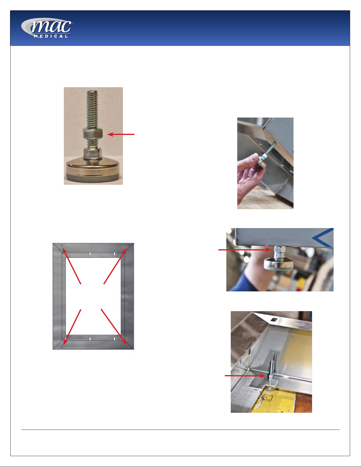
Installing Warming Cabinet leg levelers
Warming Cabinets are shipped with 4 Leg Levelers
which must installed by the customer (Fig. 7).
Jamb Nut
Fig. 7: Leg Leveler
The Warming Cabinet base has 4 holes into which
the Leg Levelers can be installed (Fig. 8).
Working with at least two people, carefully tilt the
Warming Cabinet back slightly and insert the 4 Leg
Levelers up into the 4 provided holes (Fig. 9).
IMPORTAnT: The Jamb Nut must go on the outside of
the Cabinet Base, not the inside. Fig.10 shows a Leg
Leveler correctly installed with the Jamb Nut outside
the base. Fig. 11 shows the Leg Leveler incorrectly
installed with the Jamb Nut inside the base.
Fig. 9: Insert Leg Leveler into base
Holes for
Leg Levelers
Fig. 8: Holes in Cabinet base
Jamb Nut
Fig. 10: Leg Leveler - Correct installation
Jamb Nut
Fig. 11: Leg Leveler - Incorrect installation
MAN-001
14
www.macmedical.com
Instruction Manual
2
5
2
3
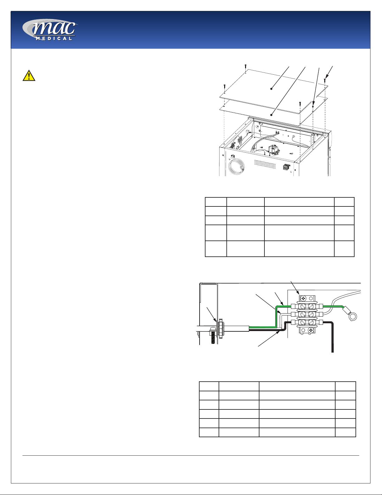
Optional Direct Wiring Using facility Power Supply
NOTE: The following procedure must be performed
by a qualied electrical technician to avoid personal
injury or damage to the unit.
Warming Cabinets can be wired directly into the
facility’s wiring by following these steps:
1. Remove four 8 X 1-5/8” self tapping screws and lift
off the Top Outer Panel. See Fig. 7.
2. Remove two 8 X 1/2” self tapping screws and lift off
the Top Inner Panel. See Fig. 7.
3. Loosen the 3/8” straight-thru connector (See Figure
4, Item 1) and disconnect wiring from terminal
board (Figure 4, Item 5) and from Fig. 8, Items 2, 3, 4.
4. Remove existing power cable (See Figure 4, Items
2, 3, and 4) from terminal block and pull out of
Warming Cabinet through 3/8” connector (See Fig.
8, Item 1).
5. Feed facility wiring cable back through the 3/8”
connector (See Fig. 8, Item 1) in the back of the
cabinet and wire onto terminal board as shown in
Fig. 8. Tighten the 3/8” to securely hold the facility
wiring in place.
6. On the terminal board, The green wire (Item 4)
connects with the green ground wire.
7. The white wire (Item 3) connects opposite with the
white wire, or neutral wire, on the terminal board.
8. The black wire (Item 2) connects opposite of the
black or positive wire on the terminal board.
9. Re-install the Inside Top Panel using two 8 X 1/2” selftapping screws. See Fig. 7.
10. Re-install the Outside Top Panel using four 8 X 1-5/8”
self-tapping screws. See Fig. 7.
11. Carefully slide the unit into its permanent location.
1
Fig. 12: Remove Top Covers
Item P/n Description Qty
1 SMW0027 Outside Top Panel 1
2 SMW0028 Inside Top Panel 1
3 H0012-01 Screw, Self-Tapping, 8
X 1/2”
4 H0012-02 Screw, Self-Tapping, 8
X 1-5/8”
3
4
1
4
2
4
MAN-001
Fig. 13: Unwiring Terminal Block
Item P/n Description Qty
1 W0140 Connector, Straight, 3/8” 1
2 W0077 Wire, Black, Positive 1
3 W0077 Wire, White, Neutral 1
4 W0077 Wire, Green, Ground 1
5 W0005 Terminal Strip, 3-Position 1
15
www.macmedical.com

basic Operation
1" OF
1" OF
SPACE
SPACE
1" OF
SPACE
This cabinet has been designed to heat:
• Liquids in vented containers.
• Liquids in non-vented containers to a temperature
of 150° F maximum (65.6°).
• Metal objects
• Muslin or 100% cotton sheets and wool blankets.
• Glass containers must be annealed borosilicate
glass (Pyrex type).
• Only plastic containers rated Thermal and
capable of withstanding temperatures in excess
of 300° F (149° C)
Instruction Manual
Fig. 14: Content Spacing
DO NOT WARM -
• Synthetic blend fabrics
• Flammable liquids
• Items containing non-thermal plastic, rubber,
metal snaps, studs, hooks, etc.
Recommended Settings
MAC Medial, Inc. does not recommend chamber
set points for any items that are to be warmed. For
appropriate heating temperatures, please contact
the item manufacturers. For more information, please
contact MAC Medical, Inc.
For blankets, follow blanket manufacturer’s
instructions for the set point.
For intravenous and irrigation uids, follow
temperature guidelines printed on the container or
contact your supplier for temperature and expiration
periods.
loading Contents in Cabinet
Load contents into the chamber with a minimum of 1
inch of space between all walls and fan to allow for
evenly distributed circulation (as seen here).
Allow 1” of spacing between uid containers for
evenly distributed heating (Fig. 9). Avoid stacking
uid bags as this increases the heating time required
to achieve set temperatures.
Blankets must be folded and stacked to allow a one
inch minimum space from the sides, back and top
of the compartment or the shelf above. Do not let
blanket protrude past the front edge of the shelf.
DO nOT OVeRlOAD.
Once a set temperature is selected and obtained
it will be controlled throughout the operations
within ± 1°F to 3°F (-1.7°C to -1.6°C) of the selected
temperature.
From a cold start, each compartment’s loaded
contents will be evenly heated to a set point within 2
to 6 hours (depending on the load). In the event of
power loss, the warmer will resume normal function
once power is restored.
For multi-chambered units, each chamber can be
loaded with different goods and set at different
temperature settings.
In Case of Power failure
In case of power failure, the unit will resume normal
operation when power is restored.
Follow the uid manufacturer’s guidelines for unused
solutions that have cooled or have been removed
from heated storage.
MAN-001
16
www.macmedical.com

explanation of the Controls
Instruction Manual
2
1
OFF
4
ON
5
9
3
7
6
8
Fig. 15: Controller Display
The Controls are located on the upper panel (Fig. 10) on the front of the cabinet. For multi-chamber cabinets,
there are sets of controls for each individual chamber. Each control set is clearly labeled UPPER CHAMBER and
LOWER CHAMBER for dual chamber cabinets and UPPER CHAMBER, MIDDLE CHAMBER and LOWER CHAMBER
for the triple chamber cabinets.
Item Control
Components
1 ON/OFF Switch/
Circuit Breaker
2 HEAT light Visual indicator that the heating system is active
3 ALARM light Visual indicator of an overheat condition
4 Display Panel Shows the current chamber temperature (Actual) and the Setpoint temperature in
Provides power to the warming compartment and control
Fahrenheit (F) or Celsius (C). The upper readout row indicates what mode will be dened/
changed (i.e. top/bottom chamber, date, etc). It also continually indicates the actual
temperature. The lower readout row indicates the settings for the mode. It also continually
indicates the setting temperature. The display also provides Loss of Power and Overheat
(Alarm). The overheat alarm is an audble and visual display “HI”.
function
Numbers/letters are entered in reverse order, working from right to left across the controller.
5 UP arrow Adjusts the setpoint of the chamber and silence the audible overheat alarm.
6 DOWN arrow Adjust the setpoint of the chamber
7 SET buttom Press to change the setpoint temperature. Press again to save a setpoint temperature. SET is
also used to move to the next setting parameter/mode
8 DATA port USB port used to retrieve temperature values for a set period of time.
9 Key Switch Used to lock out any changes to the control, such as adjusting the setpoint temperature.
MAN-001
17
www.macmedical.com

Operation of Display Panel
Instruction Manual
Start
Press the power switch to the “ON” position. (For multichamber units, each chamber has its own power
switch). The upper readout display will show the
actual chamber temperature.
Set Processing Temperature
1. Press “SET” and release.
2. Press the UP ▲ arrow key up (to raise the setpoint)
or the down ▼ arrow key (to lower the setpoint).
The setpoint is indicated in the lower row of the
display.
3. Press “SET” again to complete the change (If dual
or triple chamber unit, steps must be completed
for all chambers). The setpoint temperature will
change and the last digit will ash.
4. To prevent adjustment to the setpoint
temperature, the control may be locked with the
Key Switch (see #9, Fig. 10)
NOTE: See the Maximum/Minimum Limits Temperature
Set Points table below for various warming cabinets
and chambers.
NOTE: The temperature setting may be changed
at any time. However, if the setpoint is changed
more than 10° below the actual temperature, the HI
temperature alarm will activate.
If alarm is activated and the control panel reads “HI”,
complete the following steps:
1. Press “ALARM RESET” (UP ▲ arrow) until the alarm
stops.
2. Open door(s) to release heated air.
3. If the display reads “HI” and alarm remains, open
door(s) and allow more cooling time.
NOTE: If the alarm is activated under normal
operating conditions, turn power to specic chamber
off and call your Mac Medical representative at
1-877-828-9975.
Caution Burn Hazard: DO NOT raise the
setpoint temperature to increase the rate of heating.
This could overheat the contents leading to possible
patient burns.
Warning Explosion Hazard: DO NOT exceed
150° for non-vented closures (screw caps, crimp seals,
plastic pouches, etc. DO NOT exceed pre-sterile
solution manufacturer’s temperature requirements.
Minimum/Maximum limits Temperature Set Points and Temperature Tolerances on Warming Cabinet Units
Warmer Cabinet Model Minimum
SWC151822
Single chamber units SWC182424, SWC182436, SWC183024,
SWC182464, SWC242436, SWC243024, SWC242424
Single chamber units SWC183036, SWC243036 ±2°F
Single chamber units SWC182474, SWC183064, SWC183074,
SWC242464, SWC242474, SWC243064, SWC243074
Dual Chamber units (Upper Chamber) DWC182464T, DWC183064T,
DWC182474T, DWC183074T, DWC242474T, DWC243074T
Dual Chamber units (Upper Chamber) DWC182474E, DWC183064T,
DWC183074E, DWC242464T, DWC242474E, DWC243064T, DWC243074E
Dual Chamber units (Lower Chamber) DWC182464T, DWC182474E,
DWC183064T, DWC182474T, DWC183074T, DWC183074E,
DWC242464T, DWC242474E, DWC243064T, DWC243074E
Dual Chamber units (Lower Chamber) DWC242474T, DWC243074T ±3°F
Triple chamber models
Temperature
Set Point
90°F (32°C)
Maximum
Temperature
Set Point
135°F (57°C)
160°F (71°C)
110°F (43°C) top
chamber
135°F (57°C)
middle chamber
160°F (71°C)
bottom chamber
blankets Irrigation
30°C to 71°C
(86°F to 160°F)
fluids
30°C to 66°C
(86°F to 150°F)
Injection
fluids
30°C to 40°C
(86°F to 104°F)
Temperature
±1°F
±1°F
±3°F
±1°F
±2°F
±2°F
±1°F
±1°F
±1°F
Tolerance
MAN-001
18
www.macmedical.com

Instruction Manual
Installing the Shelves
1. Where applicable, turn the power OFF to the
heating chamber that needs a shelf installed in it.
A. Allow the heating chamber to cool. Then
unload any contents.
2. Install the 4 shelf support clips into the desired
location by inserting the top tab into the upper
wall slot of that position (Fig. 12 & Fig. 13). Push
up slightly on the inserted top tab and push the
bottom half of the clip in until the bottom tab
snaps into the lower slot.
3. Count the mounting locations at each corner of
the chamber to be sure that the shelf will be level
and install the remaining support clips.
4. Install the shelf with the notches on the bottom of
the shelf aligned with the shelf supports (Fig. 13 &
Fig. 14).
5. Pull outward on the shelf to insure it is locked
properly on the supports.
Adjusting the Shelves
1. Turn the power OFF to the heating chamber that
needs its shelf adjusted.
A. Allow the chamber to cool. Then unload the
contents.
2. Remove the shelf and determine its new position.
3. Remove the four (4 per shelf) shelf supports clips
by tilting the clip upwards and lifting out.
4. Install the shelf support into the new location by
inserting the top tab into the upper slot of the new
position. Push up slightly on the inserted top tab
and push the bottom half of the clip in until the
bottom tab snaps into the lower slot..
5. Count the mounting locations at each corner of
the chamber to be sure that the shelf will be level
and install the remaining supports.
6. Re-install the shelf with the notches on the bottom
of the shelf aligned with the shelf supports.
7. Pull outward on the shelf to insure it is locked
properly on the supports.
Fig. 16: Shelf Support
Wall Slots
Fig. 18: Support Clip Fitted in Notch
Shelf Support showing tabs
Fig. 17:
NOTE: Shelves are notched at each
corner to rest on 4 shelf support clips
that are inserted into the cabinet wall
slots (Figure 14).
Shelf Notch
Fig. 19:
MAN-001
19
www.macmedical.com

Instruction Manual
Installing and Adjusting Optional Roller basket Shelves
Install the roller basket shelf by rst attaching the two roller channels to the cabinet walls.
1. First, insert the top tab of one end of the roller channel into a slot (the roller channel width spans 4 slots). Fig.
15 & Fig. 16.
2. After inserting the top tab , push up slightly on it while snapping in the bottom tab into a slot located 3 slots
below the top slot. (Fig. 17)
3. Snap in the other end (make sure it is level with the rst end) and attach the other roller channel to the
opposite side in the same manner. Be sure both channels are level with each other.
4. Set the 2 sets of rollers of the roller basket into the channel tracks on both sides and slide the shelf in (Fig. 18 Fig. 19).
Fig. 20: Inserting Top Channel Tab
Fig. 23: Rollers in Channel Track
Adjust the Roller Basket Shelf
Fig. 21: Cabinet Wall Slots
Fig. 24: Roller Basket Shelf Installed
Fig. 22: Inserting Bottom Channel Tab
1. To adjust the roller basket shelf, slide the shelf out and lift up to clear the rollers from the roller channel track.
Set the shelf aside.
2. Remove the roller channels by pushing up slightly on the top tab of the channel and pull out the channel
from the bottom.
3. Re-install the roller channels in another location using the same installation process described above.
4. After re-installing the roller channels, re-install the shelf by aligning its rollers in the roller channel track and
sliding the shelf in.
Note: For information on basket dimensions and part numbers pertaining to warmer cabinet models, see page
26.
MAN-001
20
www.macmedical.com

Unloading the Warming Cabinet
Instruction Manual
Caution Injury and Burn Hazard: Avoid injury
by using proper personal protective equipment when
loading or unloading the Warming Cabinet. Internal
surfaces are hot, glass may shatter when cooled
suddenly and solution bags or bottles may burst when
picked up. Rotate warmed contents on a rst-in,
rst-out basis. Failure to do so may present cold or
discolored contents.
Maximum Warming Temperature limit for Patient Safety (as recommended by eCRI)
Items to be Warmed Maximum Temperature limit
Liquid Solutions for use on living tissue 110°F (43°C)
Blankets 130° (54°C)
Retrieval of Recorded Temperatures
AORN recommends the cabinet temperature
should be routinely monitored and documented on
a temperature log or on a record provided by an
electronic recording system, according to facility
policy.
All MAC Medical D-series warming cabinets are
equipped with a temperature monitoring program
that stores actual chamber temperatures in 30 minute
intervals. The information recorded may be down
loaded to a USB ash drive at any time. To retrieve
the stored data:
1. Insert the MAC Medical ash drive (W0600-S)
or equivalent into the USB port marked DATA
(located on the front face of the control panel).
For multi-chambered units, insert a ash drive into
the USB port marked DATA for each chamber.
2. The digital display will change from displaying the
actual temperature to displaying the code shown
in Fig. 20.
Warning Injury or Burn Hazard: DO nOT
use heated liquids on, or inject in, living tissue unless
actual liquid temperature has been measure and
found acceptable. The temperature of the Warming
Cabinet contents may be hotter than the displayed
temperature. For patient safety (in accordance
with optimal medical practice), always verify liquid
temperature with a themometer at the point of use.
Important: See Maximum Warming Temperature Limit
for Patient Safety table below
3. Once the transfer is complete, the digital display
will show the temperature again.
4. Remove the ash drive. The data is saved on
the ash drive as a .CSV le for import into most
Windows-based spreadsheet programs. The
example below shows the Fahrenheit temperature
variation within a certain date and time period as
shown in Fig. 21.
Fig. 25: Data Download Code
Fig. 26: Data extracted
Turning Off the Warming Cabinet
Switch the ON/OFF Switch to the OFF position for each chamber to be shut down.
MAN-001
21
www.macmedical.com

Instruction Manual
Troubleshooting
The following alert messages and operating conditions will occur when the warming cabinet is operating
outside of acceptable conditions.
Troubleshooting Guide
Alerts & Description Action Required
HI with audible alarm
LLLL
HHHH with audible alarm
OPEn with audible alarm
JIC continuous or ashing
Unit will not power up 1. Check outlet for power
Chamber does not heat 1. Is the power turned on?
Over temperature alarm
activated
Cabinet temperature is 10°F (or 5°C) higher than setpoint. Silence the alarm by pressing
ALARM RESET (Up ▲ arrow) and open door(s) to allow the chamber(s) to cool.
Input temperature is lower than input range. Check temperature probe and
connections. See below for additional troubleshooting.
Input temperature is higher than input range. Check temperature probe and
connections. See below for additional troubleshooting.
Temperature probe is at fault. Check connection, then replace and calibrate.
Control failure. Check connection rst, then replace and calibrate.
2. Check if warmer is plugged in
3. Check if the ON/OFF switch/circuit breaker is turned on
4. Check the fuse on the incoming supply
5. Check for power at the junction box in the control panel
6. Contact your MAC Medical authorized service representative
2. Is the temperature set above chamber ambient temperature?
3. Is the circulation fan operational? Open the door and press in on the door switch
4. Is there voltage on the output terminal of the controller?
5. Is the door(s) closed?
6. Contact your MAC Medical authorized service representative
7. Is the circulating fan operational?
HI is
8. Are the contents loaded properly?
9. Has the chamber set temperature been lowered?
10. Temperature of the lower chamber cannot be in excess of +30°F (+1.1°C) above the
upper chamber
11. Contact your MAC Medial authorized service representative
Overheat Alarm (HI) Condition
When the cabinet temperature exceeds the setpoint by 10°F (or by 5°C) or the set temperature is lowered
by more than 10°F (or by 5°C), the display will red HI and the audible alarm will sound. Silence the alarm by
pressing ALARM RESET (Up ▲ arrow) until the alarm quits.
Turn off the Warming Cabinet chamber and wait for the contents to cool adequately. Then unload the
contents using personal protective equipment to avoid injury. Reload the contents using the proper loading
guidelines as previously mentioned in this manual.
Turn on the chamber and monitor performance. If the chamber continues to overheat into an alarm (HI)
condition, turn off the chamber and contact your MAC Medical authorized service personnel.
MAN-001
22
www.macmedical.com

Instruction Manual
Cleaning Stainless Steel Warming Cabinets
Stainless steel Warming Cabinets must be cleaned on a regular basis to prevent any unnecessary damage to
the stainless steel surfaces. Spilled liquids and standing water should be cleaned up immediately.
When cleaning stainless steel Warming Cabinets, make sure to use the proper approved cleaning agents and
cleaning materials to protect the surface and prevent damage or corrosion.
CAUTION:
DO nOT USe
these Cleaning
CAUTION:
DO nOT USe these
Cleaning Agents
Materials
Abrasive Pads Hard Water (water with a pH
reading above 7.0).
Scrapers (metal or
plastic)
Steel Wool Steam or high pressure water
Wire Brushes Bleach or any compounds
Cleaning Stainless Steel Surfaces
Hydrochloric Acid
containing chlorine or Sodium
hypochlorate, or ammonium
chloride salts.
• Using a damp, lint-free cloth and approved
cleaner, wipe down the entire exterior surface
of the stainless steel warming cabinet. Using a
damp, lint-free cloth with distilled water and a mild
detergent, wipe down the entire exterior surface
of the stainless steel sinks.
• Clean the Warming Cabinet with the stainless steel
surface grain as shown here.
• Let cleaned Warming Cabinet air dry.
Cleaning Decals or Printed Labels
• Use only distilled water and a mild detergent
applied with a clean, dry lint-free cloth to clean
decals or printed labels.
• Cleaning agents can remove or smear any
printing from decals and print labels.
• Cleaning agents can damage plastic materials
used in manufacturing covers for electronic items
such as touch-screen pads.
Approved cleaning materials and agents
Soft, clean lint-free
cloth
Mild detergents Sodium
White vinegar (in a
spray bottle)
Cleaners
approved for use
on stainless steel
Disinfecting Stainless Steel
Non-abrasive
cleaning pads
Bicarbonate
(baking soda)
Isopropyl
Alcohol
Soft bristle brush
Distilled water (pH
rating 7) alone
or with a mild
detergent
Hospital-grade
non-bleach
disinfectants
• Use a hospital grade non-bleach disinfectant.
Always follow the manufacturer’s instruction for
proper use of these products.
Cleaning the Warming Cabinet Interior:
• Unplug and remove the Warming Cabinet from its
power supply.
• CAUTION: Turn OFF Circuit Breaker if Warming
Cabinet is hard wired into the facility’s electrical
supply.
• Open the door and remove all adjustable shelves
and shelf clips.
• Clean the adjustable shelves and shelf clips
separately.
• Using a damp, lent free, cloth and approved
cleaner, wipe down the interior of the cabinet.
• Use a lint free dry cloth to dry the cabinet’s interior
or let air dry. If air drying, ALWAYS leave the
cabinet door open.
Cleaning Glass Doors (if applicable):
Use a commercially prepared ammonia-free glass
cleaner or use distilled water and a mild detergent
applied with a lint-free cloth.
MAN-001
23
www.macmedical.com

Preventative Maintenance Checklist
Operator Maintenance
Users are responsible for the thorough inspection of the
equipment before and after each use. Should any
problems or deciencies arise, the results must be reported
to the facilities maintenance personnel. The safety of
personnel and patients relies on the proper and routine
maintenance of this equipment.
Daily Checklist
1. Ensure that the correct operation and maintenance
manual is available to all users.
2. Ensure that all personnel using this appliance have
been properly trained in the warmer cabinet operation
and safety instructions.
3. DO NOT overload cabinet. Load contents (blankets
or uids) into the chamber with a minimum of 1 inch of
space between walls and fan to allow for circulation
(as seen below).
" OF
PACE
1" OF
SPACE
1" OF
SPACE
Instruction Manual
6. Periodically check the alarm by setting the
temperature ±15° from set point to test the alarm. If
the temperature rises or drops 15° below its set point,
the alarm should buzz and its light goes on. (Note:
90° is the lowest temperature point. To test alarm
from this point, heat the unit up 15° beyond its lowest
temperature, then bring the set point down to test the
alarm.)
Monthly Checklist
1. Check condition of casters or feet. Ensure components
are secure and tightly threaded.
2. Check control panel overlay condition. Are there any
tears or excessive wear on the graphic? Does the
control work properly when buttons are pushed?
3. Is the set temperature comparable to the actual
temperature displayed? Check chamber air
temperature with a quality thermocouple placed 1”
(25mm) from the chamber. Do not allow the sensor to
touch any surface. Monitor for approximately one hour
in an empty chamber.
Weekly Checklist
1. Inspect condition of plug and cord. Replace if
damaged.
2. Clean dust from back and side vents.
3. If any of the chamber shelves are unstable when
setting objects on them, check the shelf clips that the
shelves sit upon. Make sure these are not loose. If any
are loose, snap back into place.
4. Check basket shelves (if applicable) and side rail
condition. Do the baskets move smoothly and freely?
5. Check that all control indicators (heat and alarm)
and LED display light up. LED Display panel must show
lighted top and bottom displays. Heat light will stay
on solid while the unit is heating up to its Set Point
Temperature. Once the Set Point temp is reached, the
light will begin to pulsate, and will continue to pulsate
to maintain the Set Point temp.
MAN-001
Semi-Annual Checklist
1. Check the temperature accuracy on a semi-annual
basis by placing an IR Temp probe or thermocouple
on calibrated meter near the fan inlet. In general,
air temperature should be ±1°F for upper chamber
and counter top units and ±3°F for lower chambers
and large single cabinet units. See table column
“Temperature Tolerance” on page 18 for details. If
the cabinet is not within these guidelines, contact MAC
Medical for further assistance.
2. Inspect the Fan blades for buildup of lint and other
debris. Clean as necessary. nOTe: MAC Medical
recommends replacing the Fan Motor with Fan blade
(Part # - W0036 (120V)/ W0106 (220V)) every 2 years to
ensure uninterrupted service.
24
www.macmedical.com

Instruction Manual
Replacement Parts - General
D-Series Warming Cabinet replacement parts listed on this page have been identied by MAC Medical as
serviceable by facility personnel and are available for purchase. To obtain MAC Medical certied parts and
authorized services, contact your MAC Medical representative.
Item Part # Description QTY
1 W0102 - Key Key only - Key Lockout (2 keys per set)
Single Chamber (1 set), Dual Chamber (2 sets), Triple Chamber (3 sets)
2 SWW0055 Adjustable Shelf As Required
3 W0050 Handle, Stainless Steel Door , LH Upper, RH Lower (Dual/Triple Upper
Chamber)
W0051 Handle, Stainless Steel Door, LH Lower, RH Upper (Dual Lower Chamber, Triple
Middle Chamber)
W0052 Handle, Stainless Steel Door Single Chamber & Triple Lower Chamber 1
W0053 Handle, Glass Door 1
4 H0006-1 8-32 X 1/2” Undercut Flat Head Screw (used with W0050, W0052, W0052) 3 per handle
H0008-1 8-32 X 1/2” Screw (used with W0053) 2 per handle
5 W0043 Clip, Shelf 4 per shelf
6 W0135 Leg Leveler 4
7 W0600-S USB Drive, Data Retrieval (1 per chamber) As Required
MAN-001
25
www.macmedical.com
As Required
1
1

Replacement Parts - Header Assembly and electrical Drawer
The Parts identied in this section require an authorized
MAC Medical service technician.
Injury Hazard: The design of the Warming Cabinet
allows limited user serviceable parts or procedures. For
optimal usage, safety and durability of the product,
service must be performed by a MAC Medical authorized
service technicians using MAC Medical authorized
replacement parts and service techniques.
Instruction Manual
Fig. 27: Replacement parts in header assembly
MAN-001
Fig. 28: Replacement Parts in drawer assembly
26
www.macmedical.com

Instruction Manual
Table 1
Item # Part # Header Assembly and electrical
Drawer Parts Description
1 W0011 Power Switch 10 See table 2 Heating Element
2 W0083 Solid State Relay 11 W0010 Ceramics
3 W0137 Heat Sink Pad 12 W0037 Thermocouple
4 W0102 Key Lock Housing 13 W0042 Overtemp Thermostat
5 W0084-D Control W/Data Display Logger 14 See Table 3 Fuses
6 W0108 10” Data Cable 15 W0004
7 H0141 Cam Lock 16 W0013
8 H0708-07 Cam Lock Latch 17 W0012
9 W0036
W0106
Fan Motor with Fan blade (120V)
Fan Motor with Fan blade (220V)
Table 2 (Heating Element - Item 10)
Part # Size Volt/Watt Where Used
W0131 8” 110V/350W SWC151822
W0313-220 8” 220V/350W SWC151822-220
W0069 9” 110V/350W SWC182424, SWC243024, DWC182464, DWC182474E, DWC243024, DWC242474T,
W0069-220 9” 220V/350W SWC182424-220, DWC182464T-220
W0069-01 9” 110V/750W SWC183064, SWC183074, SWC243074, SWC182464, DWC242474T
W0069-01-220 9” 220V/750W SWC183064-220 SWC183074-220, SWC243074-220, SWC182464-220, DWC242474T-220,
W0302 9” 110V/650W SWC243036, SWC182424, SWC182436, SWC182474, SWC183036, SWC242424, SWC242436,
W302-220 9” 220V/650W SWC183036-220, SWC243036-220, DWC183074E-220, DWC182474T-220, DWC183064T-220,
W0003 12” 110V/750W SWC243024, SWC243036, SWC243074, DWC243024, DWC243064T, DWC243074E
W0107 12” 220V/750W SWC182424-220, SWC182464-220, SWC183024-220, SWC242474-220, SWC243024-220,
DWC183064T, DWC243074T, TWC243078
TWC243078-220
SWC242464, SWC243064, DWC182474E, DWC183074E, DWC183064T, DWC183074T,
DWC182464T, DWC182474T, DWC242474E, DWC243074T, TWC243078
DWC243074T-220, DWC182464T-220, TWC243078-220
SWC243074-220, DWC182464T-220, DWC243074T-220, DWC242464T-220, DW242474T-220,
DWC183064T-220
Item # Part # Header Assembly and electrical
Drawer Parts Description
W0188
W0013-220
W0012-01
18 W0525-04 USB Plug to Panel Recept 12”
Fuse Holder
Fuse Holder (for 1518 models)
Buzzer 110V
Buzzer 220V
Door Switch
Door Switch w/long stem (bottom glass
doors on dual chamber units, all stainless
steel doors)
Table 3 (Fuses - Item 14)
Part # Description Where Used
W0395
(220V)
W0396
(220V)
W0124
(110V)
W0125
(110V)
MAN-001
Fuse 7A
(2 needed)
Fuse 10A
(2 needed)
Fuse 15A All 110V Single chamber cabinets
Fuse20A All 110V Dual and Triple chamber cabinets
All 220V Single Chamber Cabinets
All 220V Dual/Triple Chamber Cabinets
27
www.macmedical.com

Instruction Manual
Optional Cabinet bases, Mobile bases
and Mobile Stands
All warming cabinets are shipped with
a standard 4” base unless otherwise
specied. The table on the right lists the
base part number and sizes for various
SWM0307-02 shown here
sized cabinets.
The two tables below list the mobile
bases/stand part numbers for the single,
dual and triple cabinets.
Single Cabinet Model # Mobile Stand/
basePart #
SWC151822 MS1518 18”D x 21”W x 34”H
SWC182424, SWC182436 MS1824 20”D x 28”W x 34”H
SWC183024, SWC183036 MS1830 20”D x 34”W x 34”H
SWC242424, SWC242436, MS2424 26”D x 26”W x 34”H
SWC243024, SWC243036 MS2430 26”D x 34”W x 34”H
SWC182464, SWC182474 MB1824 21”D x 25”W x 6.75”H
SWC183064, SWC183074 MB1830 21”D x 31”W x 6.75”H
SWC242464, SWC242474 MB2424 27”D x 25”W x 6.75”H
SWC243064, SWC243074 MB2430 27”D x 31”W x 6.75”H
Overall
Dimensions
Dual/Triple Cabinet Model # Mobile base
Part #
DWC182474E, DWC182464T,
DWC182474T
DWC183064T, DWC183074T,
DWC183074E, TWC183078
DWC242474E, DWC242464T,
DWC242474T
DWC243064T, DWC243074E,
DWC243074T, TWC243078
MB1824
MB2424
MB1830
MB1824 21”D x 25”W x 6.75”H
MB1830 21”D x 31”W x 6.75”H
MB2424 27”D x 25”W x 6.75”H
MB2430
MB2430
Overall
Dimensions
27”D x 31”W x 6.75”H
Roll Out
basket
Part #
WB1518 SWC151822 11.5”D x 8.5”W x 2.5”H
WB1824 SWC182424, SWC182436,
WB1830 SWC183024, SWC183036,
WB2424 SWC242424, SWC242436,
WB2430 SWC243024, SWC243064,
Part # base
SMW0307-02 4” base for 18 x 24 cabinets
SMW0359-02-WM 2” base for 18 x 24 cabinets
SMW0359-03-WM 6” base for 18 x 24 cabinets
SMW0062-02 4” base for 18 x 30 cabinets
SMW0047-08 2” base for 18 x 30 cabinets
SMW0062-03 6” base for 18 x 30 cabinets
SMW0308-01 4” base for 24 x 24 cabinets
SMW0308-05 2” base for 24 x 24 cabinets
SMW0308-04 6” base for 24 x 24 cabinets
SMW0047-03 4” base for 24 x 30 cabinets
SMW0047-10 2” base for 24 x 30 cabinets
SMW0047-09 6” base for 24 x 30 cabinets
MS1518 & MS1824 MS1830 & MS2430
WB1518, WB1824,
MS2424
Warming Cabinet Model # basket Overall Dimensions
SWC182464, SWC182474,
DWC182464T, DWC182474T,
DWC182474E
SWC183064, SWC183074,
DWC183064T, DWC183074T,
DWC183074E, TWC183078
SWC242464, SWC242474,
DWC242464T, DWC242474T,
DWC242474E
SWC243074, DWC243036,
DWC243064T, DDWC243074T,
DWC243074E, TWC243078
WB1830, WB2424,
WB2430
16”D x 16.92”W x 5”H
15.88”D x 22.98”W x 5”H
21.75”D x 16.98”W x 5”H
21.75”D x 23.10”W x 5”H
MAN-001
28
www.macmedical.com

Instruction Manual
Steel or Glass Door Hinge Reversal
Before the Door Hinges can be reversed, the top and side
panels of the cabinet must be removed, and the Cam Lock must be
relocated.
Remove Panels
The Following steps for panel removal apply to cabinets with either
steel or glass doors.
1. For both glass and stainless steel doors, remove the outside top
panel by unscrewing the 4 top panel screws and lifting the panel
out. Remove the inside top panel by unscrewing the 2 screws and
lift the panel out (Fig. 29).
Fig. 29: Remove Top Panels
2. Remove the 2 screws located inside the cabinet (one on each side) near the bottom. (Fig. 30 and Fig. 31.
Door removed for clarity in these illustrations.)
Fig. 30: Remove Interior Cabinet Screws - Glass Door Unit
3. Remove the screws at the back of the
cabinet and slide out both side panels
MAN-001
Fig. 31: Remove Interior Cabinet Screws - Steel Door Unit
Fig. 32: Remove Side Panels
29
www.macmedical.com

Remove Header Assembly box & Relocate Cam lock
Purchase Parts needed for Cam lock Reversal
• Felt Strip ST0014
• Plug W0098
The following steps apply to cabinets with steel or glass doors.
Cabinets are equipped with a cam lock in the header
assembly. This must be moved to the other side of the
header assembly box when the door hinges are reversed.
The door itself has a cam lock plate which also must be
moved near the new location of the cam lock (Note: Only
top doors on multi-chambered have a cam lock plate.)
4. To remove the Header Assembly Box, unscrew 4 hex
locking bolts from the header assembly box mounting
plates and remove the header assembly box. (Fig. 33)
Instruction Manual
Fig. 33: Remove Header Assembly Box
5. To access the cam lock and
its new location, cut an area
out of the gasket cover in the
location shown by the red
rectangles (Fig. 34)
Fig. 34: Cut Out Rectangular Sections from Gasket
Fig. 35 shows the header assembly interior (gasket removed for clarity). The cam lock (in red rectangle) will be
moved to the 2 oblong knock-out areas circled in red and highlighted in blue (Fig. 36).
Fig. 35: Cam Lock to be Moved to New Location
Fig. 36: Knock out areas
MAN-001
30
www.macmedical.com

Instruction Manual
6. At the new cam lock location, remove the 2 oblong knock-out areas. Cut an oblong shape in the plastic
overlay covering the short-wide oblong knock-out area to accomodate the cam lock when it is re-installed
(Fig. 37 and Fig. 38). The narrow-long oblong knock-out area will be the slot the cam lock latch ts in.
Fig. 37: Overlay - Cam Lock Location - Right Hand Fig. 38: Overlay-Cam Lock Location - Left Hand
7. To detach the Cam Lock assembly, unscrew the Phillips head screw from the Cam Lock Latch (Fig. 39).
8. Unscrew the Hex Nut and remove the Lock Washer.
9. Pull the Cam Lock body out from the face of the Header Assembly.
10. Insert purchased Plug (W0098) into the hole originally occupied by the lock.
11. To re-install at the new position, slide the Trim ring onto the barrel of the Cam lock, insert Cam Lock body
through the oblong hole at the new position in the face of the header (Fig. 40).
Fig. 39: Detach Cam Lock Assembly
Fig. 40: Re-assemble and Re-install Cam Lock
MAN-001
31
www.macmedical.com

Fig. 41: Assembled Cam Lock
Instruction Manual
12. Secure the Cam Lock body to the header by attaching the Lock Washer, then
the Hex Nut.
13. Afx the Cam Lock Latch to the Cam Lock body and secure it with a 8-32
Phillips head screw.
14. Insert the purchased Felt Adhesive Strip (ST0014) between the Cam Lock Latch
and the header. Position it to keep the cam lock latch from falling down when
the key is in the lock (Fig. 42). When activating the lock, the latch will rub the
felt strip.
15. Use a piece of Felt Adhesive Strip to cover up the old oblong hole where the
cam lock latch passed through the bottom of the header.
16. Re-install the Header Assembly and secure to the cabinet with its 4 screws.
Fig. 42: Assembled Cam Lock with Felt Adhesive Strip Fig. 43: Cam Lock Assembly Parts
MAN-001
32
www.macmedical.com

Glass Door Hinge Reversal and Re-installation
Following are instructions for the removal, hinge
reversal, and re-installation of Glass Doors.
note: No additional parts are required to perform
Glass Door hinge reversal. However, it may be necessary to drill holes in the bottom of the Glass Door
to enable relocation of the Cam Lock Plate to its
new position. The following tools will be necessary
for this procedure:
• 1/8” Drill Bit
• 8/32 Tap
Instruction Manual
Fig. 44: Glass Door Hinge Parts
1. Using a drift pin (or a small headed screwdriver) and a
hammer, detach the glass door from the unit by tapping
lightly on the hinge pins, driving them through the two
halves of the hinges. Then pull the door away from the
unit to remove it (Fig. 45).
2. Detach the male halves of the glass door hinge by
unscrewing them from the warming cabinet. The hinge
halves on the door should remain in place (Fig. 46).
Fig. 45: Remove Door Hinge Pins
MAN-001
33
Fig. 46: Detach Glass Door Hinge - Male Half
www.macmedical.com

Instruction Manual
3. Unscrew the Door Handle and Cam Lock Plate from their present position and move them to the other
side of the door. Make sure to “mirror” the Cam Lock Plate so that its top ange will be ush against the
warming cabinet when the door is re-installed in its new position (Fig. 47).
Fig. 47: Remove Cam Lock and Handle
4. If it is necessary to drill holes for the relocation of the Cam Lock Plate on the other side of the door,use the
Cam Lock plate as a guide to mark the proper location of the holes to be drilled (Figure 48). The Cam Lock
Plate should be positioned 1/8” from the outer edge of the door (Figure 49).
Door Inner Face
Fig. 48: Use Cam Lock for hole guide Fig. 49: Proper position of Cam Lock
MAN-001
34
Cam Lock Plate set back
1/8” from outer face of door
www.macmedical.com

Instruction Manual
5. Once the holes are drilled for the Cam Lock Plate, move both the Cam Lock Plate and the Door Handle to
their new positions (Figure 50). When installed, there should be at least a 1/4” gap between the Cam Lock
Plate and the face of the Cabinet (Figure 51).
Fig. 50: Attach Cam Lock Plate and Door Handle
Fig. 51: Cam Lock Plate door gap
6. With the door handle and the cam lock plate in their new positions, rotate the door 180° (Fig. 52). Fig.53
shows its orientation when re-installing the door on its new hinge position.
Fig. 52: Rotate Modied Door
MAN-001
Fig. 53: Door Rotated to New Installation Position
35
www.macmedical.com

Instruction Manual
7. Use a athead screwdriver to remove the 2 smaller satin plugs (circled in red) from the top and bottom of
the opposite side of the cabinet. These are the new hinge positions (Fig. 54).
8. Re-insert the 2 satin plugs (that were removed from the new hinge positions) in the old hinge positions.
Fig. 54: Remove Satin Plugs from New Hinge Position
9. Re-install the male halves of the door hinges in these positions. Do not tighten the screws at this point (Fig.
55).
10. Attach the glass door to the unit by tting the two halves of the glass door hinges together, Before securing
the door to its hinges, square the door by checking the door’s alignment with the header assembly box.
Then tighten the hinge screws (Fig. 56).
Fig. 55: Install Male Hinge Halves in New Position Fig. 56: Check Alignment - Square Door
MAN-001
36
www.macmedical.com

Instruction Manual
11. To secure the door to its hinges, drive the hinge pins through the two halves of the hinges. Both pins should
be driven into the hinges from the inside to the outside as shown in Fig. 57.
12. Re-attach and secure the side panels to the warming cabinet with its screws.
13. Re-insert the 2 interior cabinet screws near the bottom of the cabinet chamber.
14. Re-install the inner and outer top panels and secure with its screws.
Fig. 57: Insert Hinge Pins
MAN-001
37
www.macmedical.com

Steel Door Hinge Reversal and Re-installation
Purchase Parts needed for Door Hinge Reversal
• Intermediate Hinge (for multiple door units only) W0015 (Right Hand)
or W0016 (Left Hand). Obtain the intermediate hinge opposite of the
currently installed hinge.
1. Loosen the nuts on the bolts that hold the top door hinge onto the
unit. Hold the door as you remove the nuts so the door does not fall
on you. Once the nuts are removed, the door can be leaned away
from the unit and lifted off the bottom hinge (Fig. 58).
Instruction Manual
Fig. 58: Remove Steel Door
2. Remove the nuts that fasten the bottom hinge to the unit and remove
the screws and bottom hinge (Fig. 59).
Fig. 59: Remove Bottom Hinge
Fig. 60: Steel Door Hinge Parts
W0016
Left hand
Fig. 61: Intermediate Door Hinge
W0015
Right hand
note: For warming cabinets with more than one door, an
intermediate hinge (Fig. 61) ts between the bottom of the top
door and the top of the bottom door of the dual chambered
warming cabinet (shown in blue in Fig. 62. (Middle doors on Triple
chamber warming cabinets use only intermediate hinges for both
top and bottom.)
Fig. 62: Intermediate Door Hinge in Place
Intermediate hinges come as either right hand (part #W0015) or left hand (part #W0016) hinges. Purchase the
intermediate hinge that is the opposite of the current one on your warming cabinet.
If the unit has multiple doors, remove the intermediate hinges by unscrewing them from the cabinet.
MAN-001
38
www.macmedical.com

3. After the door is removed, unscrew the Door Handle and Cam
Lock Plate from their present position and move them to the
bottom of the door. Be sure to “mirror” the Cam Lock Plate
so that its top ange will be ush against the warming cabinet
when the door is re-installed in its new position (Fig. 63).
4. With the door handle and the cam lock plate transferred
to their new positions, rotate the door 180°. This will be its
orientation when re-installing the door on its new hinge position.
Instruction Manual
Fig. 63: Move Door Handle and Cam Lock Plate
5. From the opposite side of the cabinet, use a athead
screwdriver to remove the 2 top satin plugs (Fig. 64) from the
top and the 2 lowest bottom satin plugs. These are the new
hinge positions.
6. Re-insert the 2 satin plugs (that were removed from the new
hinge positions) in the old hinge positions.
Fig. 64: Remove Satin Plugs
7. Attach the bottom hinge in the new position to the bottom
of the unit using the hardware provided (Fig. 65).
MAN-001
39
Fig. 65: Install Bottom Hinge in New Position
www.macmedical.com

8. Look at the socket located on both the top and bottom of the door
(circled in red in Fig. 66). The pins of the door hinges will insert into these.
Fit the bottom socket of the door onto the bottom hinge pin. Support
the door on its bottom hinge while you prepare to afx the door to the
top hinge.
9. Insert the screws into the top hinge (or intermediate hinge, if
applicable). Then insert the hinge pin into the top socket of the door,
aligning the hinge screws with the top (or intermediate) hinge holes on
the unit as shown in Fig. 67.
Fig. 66: Door Hinge Socket
10. From the side of the unit, secure the door
and top hinge with the hinge nuts shown
circled in red in Fig. 67.
Instruction Manual
Fig. 67: Install Top Hinge and Secure Door
11. Square the door by checking its alignment with
the header (Fig. 68 shows a glass door, but the
same applies for the steel door). Then tighten
the hinge nuts.
12. Re-attach both side cabinet panels with its
screws
13. Re-insert the 2 interior cabinet screws near the
bottom of the cabinet chamber.
14. Re-attach the inner and outer top cabinet
plates.
MAN-001
40
Fig. 68: Check Alignment - Square Door
www.macmedical.com

Wiring Diagram - Single Chamber Warmers
Instruction Manual
MAN-001
41
www.macmedical.com

Wiring Diagram - Dual Chamber Warmers
Instruction Manual
MAN-001
42
www.macmedical.com

Wiring Diagram - Triple Chamber Warmers
Instruction Manual
MAN-001
43
www.macmedical.com

Instruction Manual
Index
C
Cabinet bases, Mobile bases and Mobile Stands 26
Cleaning 21
Approved cleaning materials and agents 21
Decals or Printed Labels 21
Disinfecting Stainless Steel 21
Glass Doors 21
Prohibited Cleaning Materials & Agents 21
Stainless Steel Surfaces 21
Controls 15
Control Components 15
D
Door Hinge Reversal 27
Glass Doors 30
Steel Doors 33
I
Installation 12
Direct Wiring to Facility Power Supply 13
Environmental Conditions 12
M
Maintenance 22
Daily Checklist 22
Monthly Checklist 22
Semi-Annual Checklist 22
Weekly Checklist 22
O
Operation 14
Display Panel 16
Set Processing Temperature 16
Items permitted for warming 14
Items prohibited for warming 14
Power Failure 14
Proper Content Loading 14
Recommended Settings 14
P
Patient Safety
Maximum Warming Temperature Limit 19
R
Replacement Parts
General 23
Header Assembly and Electrical Drawer 24
S
Shelves
Adjusting 17
Installation 17
Roller Basket
Adjusting 18
Installation 18
Part Numbers 26
Specications 7
Cabinet Construction and Material 7
Electrical Specications 7
Factory Presets 7
Power Requirements 7
T
Temperature Issues
Checking Accuracy 22
Data Retrieval 19
Temperature Set Points 16
Temperature Tolerances 16
Troubleshooting 20
Alerts 20
Overheat Alarm (HI) Condition 20
U
Unpacking 11
Inspection 11
Receiving Requirements 11
W
Warming Cabinets
Interior Dimensions & Capacity 5
Main Features 8
Models 4
Overall Size 4
Turning Off 19
Unloading 19
Usable Chamber Space 6
Warnings and Cautions 9
Intended Use Notice 10
Special User Attention 10
Warranty Information 40
Wiring Diagram
Dual Chamber Warmers 37
Single Chamber Warmers 36
Triple Chamber Warmers 38
MAN-001
44
www.macmedical.com

Instruction Manual
Preventative Maintenance Record
for your convenience, here is a simple chart to use to note which personnel have been trained to
safely use and maintain the warming cabinet.
Personnel Trained Daily Operation Safety Instruction Cleaning Procedures
This chart refers to the procedures on the “Preventative Maintenance Checklist” on page 56.
Date of Weekly Inspection Date of Monthly Inspection Date of Semi-Annual Testing
MAN-001
45
www.macmedical.com

Instruction Manual
notes
__________________________________________________________________________________________
__________________________________________________________________________________________
__________________________________________________________________________________________
_________________________________________________________________________________________
_________________________________________________________________________________________
__________________________________________________________________________________________
__________________________________________________________________________________________
__________________________________________________________________________________________
__________________________________________________________________________________________
__________________________________________________________________________________________
__________________________________________________________________________________________
__________________________________________________________________________________________
__________________________________________________________________________________________
__________________________________________________________________________________________
__________________________________________________________________________________________
__________________________________________________________________________________________
__________________________________________________________________________________________
__________________________________________________________________________________________
__________________________________________________________________________________________
__________________________________________________________________________________________
__________________________________________________________________________________________
__________________________________________________________________________________________
__________________________________________________________________________________________
__________________________________________________________________________________________
__________________________________________________________________________________________
__________________________________________________________________________________________
__________________________________________________________________________________________
__________________________________________________________________________________________
__________________________________________________________________________________________
__________________________________________________________________________________________
__________________________________________________________________________________________
__________________________________________________________________________________________
__________________________________________________________________________________________
__________________________________________________________________________________________
__________________________________________________________________________________________
_________________________________________________________________________________________
_________________________________________________________________________________________
__________________________________________________________________________________________
__________________________________________________________________________________________
__________________________________________________________________________________________
__________________________________________________________________________________________
__________________________________________________________________________________________
MAN-001
46
www.macmedical.com

Instruction Manual
notes
__________________________________________________________________________________________
__________________________________________________________________________________________
__________________________________________________________________________________________
_________________________________________________________________________________________
_________________________________________________________________________________________
__________________________________________________________________________________________
__________________________________________________________________________________________
__________________________________________________________________________________________
__________________________________________________________________________________________
__________________________________________________________________________________________
__________________________________________________________________________________________
__________________________________________________________________________________________
__________________________________________________________________________________________
__________________________________________________________________________________________
__________________________________________________________________________________________
__________________________________________________________________________________________
__________________________________________________________________________________________
__________________________________________________________________________________________
__________________________________________________________________________________________
__________________________________________________________________________________________
__________________________________________________________________________________________
__________________________________________________________________________________________
__________________________________________________________________________________________
__________________________________________________________________________________________
__________________________________________________________________________________________
__________________________________________________________________________________________
__________________________________________________________________________________________
__________________________________________________________________________________________
__________________________________________________________________________________________
__________________________________________________________________________________________
__________________________________________________________________________________________
__________________________________________________________________________________________
__________________________________________________________________________________________
__________________________________________________________________________________________
__________________________________________________________________________________________
_________________________________________________________________________________________
_________________________________________________________________________________________
__________________________________________________________________________________________
__________________________________________________________________________________________
__________________________________________________________________________________________
__________________________________________________________________________________________
__________________________________________________________________________________________
MAN-001
47
www.macmedical.com

limited lifetime Warranty
MAC Medical warrants to the original purchaser that its Proprietary Products will be free from
defects in workmanship or materials under normal use and service for the life of the product, so
long as owned by the original purchaser, according to the limitations set forth below.
Defective products shall be repaired or replaced at MAC Medical’s option at no cost to the
original purchaser provided:
1. The customer must obtain a written return authorization supplied by MAC Medical’s
customer service department. The product must be returned, properly packaged, with a
copy of the original sales receipt and copy of the RMA authorization. Please call (877) 8289975 or (618) 476-3550 to receive a return authorization.
2. The customer must pre-pay freight charges to and from MAC Medical and must ship
merchandise properly packaged, in a way the product will not be damaged during transit
to the factory. MAC Medical does not warranty any freight damage to or from the factory. It
is the customer’s responsibility to inspect the product for packaging damage before signing
the BOL.
This warranty does not apply to products, which have been subject to abuse, misuse, accident,
modication, alteration, tampering, negligence, lack of routine maintenance or misapplication;
or products that have been repaired by other than MAC Medical or its authorized
representatives.
This warranty does not apply to glass, fabrics, vinyl, seat coverings, cushions, padding or their
stitching, gluing or installation. Component parts not manufactured by MAC Medical, such
as casters, caster inserts, any components made from rubber or plastic, circuit boards, fan
heaters, plumbing parts, electrical switches and other components are also excluded. For
these component parts, MAC Medical will pass on the original manufacturer’s warranty to
MAC Medical equipment original purchasers. Please consult factory for questions regarding
the warranties of these component parts. This warranty does not apply to custom fabricated
products. Consult factory.
UNLESS EXPRESSLY SET FORTH IN THIS WARRANTY, THERE ARE NO OTHER WARRANTIES, WHETHER
EXPRESS OR IMPLIED, OF FITNESS AND / OR MERCHANTABILITY OR ANY OTHER WARRANTY IMPLIED
BY CUSTOM, USAGE OR COURSE OF DEALING.
Liability of MAC Medical under this warranty is limited to the repair and / or replacement of any
products. MAC Medical specically excludes and disclaims any responsibility for any incidental
or consequential damages claimed to have arisen from any defect in workmanship or materials.
No representative has any authority to change or enlarge the above warranty or MAC Medical
liability. This document supersedes all previous warranty provisions.
To place an order, contact our customer service
department at 618-476-3550 or 877-828-9975 or
by email at sales@macmedical.com
MAC Medical, Inc.
Printed in USA
Publication No. MAN-001 Rev J
October 2018
Information regarding this product is
subject to change without prior notice.
Customer needs are our rst priority.
Corporate Ofce
325 West Main Street
Belleville, IL 62220
Phone: 618-476-3550 • Toll Free: 877-828-9975 • www.macmedical.com
Manufacturing Plant
820 South Mulberry Street
Millstadt, IL 62260
 Loading...