

Page 1
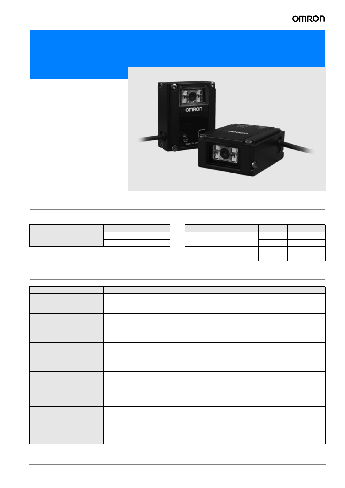
Code Reader
V400-R1
Multi-code reading
at a touch
• Accurate reading of Barcode and Datamatrix
• Easy adjustment of parameters
• 1.3 MPixel CMOS image sensor
• Flexible installation: front and side view
variants
Ordering information
Code Reader Cables
Name Type Order code
Multi Code Reader Front view V400-R1CF
Side view V400-R1CS
Name Length Order code
PC communication cable
(incl. Power)
PLC communication cable
(incl. Power)
Specifications
Item V400-R1CF/V400R1CS
Bar code
2D code DataMatrix (ECC200), QR Code, Micro QR Code, PDF417, RSS
Number of reading digits No upper limit (depends on bar width and reading distance)
Light source Four red LEDs (wave length: 630 nm)
Aiming light Two green LEDs (wave length: 527 nm)
Minimum resolution 0.1 mm (bar code), 0.169 mm (2D code)
Image capture device CMOS area sensor (1280 (H) x 1024 (V))
Working distance (WD) 60 mm
Field of view 52 x 41 mm (for WD = 60 mm)
Skew angle -50 to 0°, 0 to +50°
Pitch angle -50 to 0°, 0 to +50°
Tilt angle 360°
Reading of bar codes on curved
surfaces
Communication specification RS-232C
OK/NG outputs NPN open collector output
Function setting method Menu sheet reading method or host command method
Reading trigger
JAN/EAN/UPC (A, E), CODE39, NW-7, ITF
Industrial2of5, CODE93, CODE128 (including EAN128), RSS
R > 15 mm (JAN8), R > 20 mm (JAN13)
External trigger (Transistor input)
Trigger by command (RS-232C)
Trigger a test reading by pressing the SCAN button on the product
0.8 m V509-W011D
5 m V509-W016D
0.8 m V509-W011
5 m V509-W016
1V400-R1
Page 2
Item V400-R1CF/V400R1CS
OK signal is turned on to indicate a successful read
OK/NG signals
OK signal is turned on to indicate a successful read of registered label
NG signal is turned on to indicate a successful read of a non-registered label
Indication LED
OK LED (green) illuminates to indicate a successful read
NG LED (red) illuminates for failed reading with an error message output
Buzzer Notifies a successful reading with a buzzer sound (Muting available)
Power voltage 4.5 to 5.5 VDC
Consumption current During operation: 500 mA or less; during standby: 300 mA or less
Ambient temperature At operation: 0 to + 45° C; At storage: 2 to + 60° C
Ambient humidity At operation and storage: 20 to 85% RH (with no icing or condensation)
Ambient atmosphere No corrosive gases
Ambient light resistance 10,000 lx (fluorescent lamp), 100,000 lx (sunlight)
Vibration resistance
12 to 100 Hz, 19.6 m/s
2
(2G), 1 hour each in three directions
Degree of protection IP54 (IEC60529)
Weight Approximately 270 g (including cables, ferrite core, mounting bracket, insulation board and screws)
Dimensions 58 x 46 x 24.2 mm
Input connector Round DIN connector
Accessories
Operation manual, ferrite core, menu sheet, mounting bracket, insulation board, M3 x 8 screws (four),
M5 x 10 screws (two)
Housing Aluminum die-cast (ADC12)
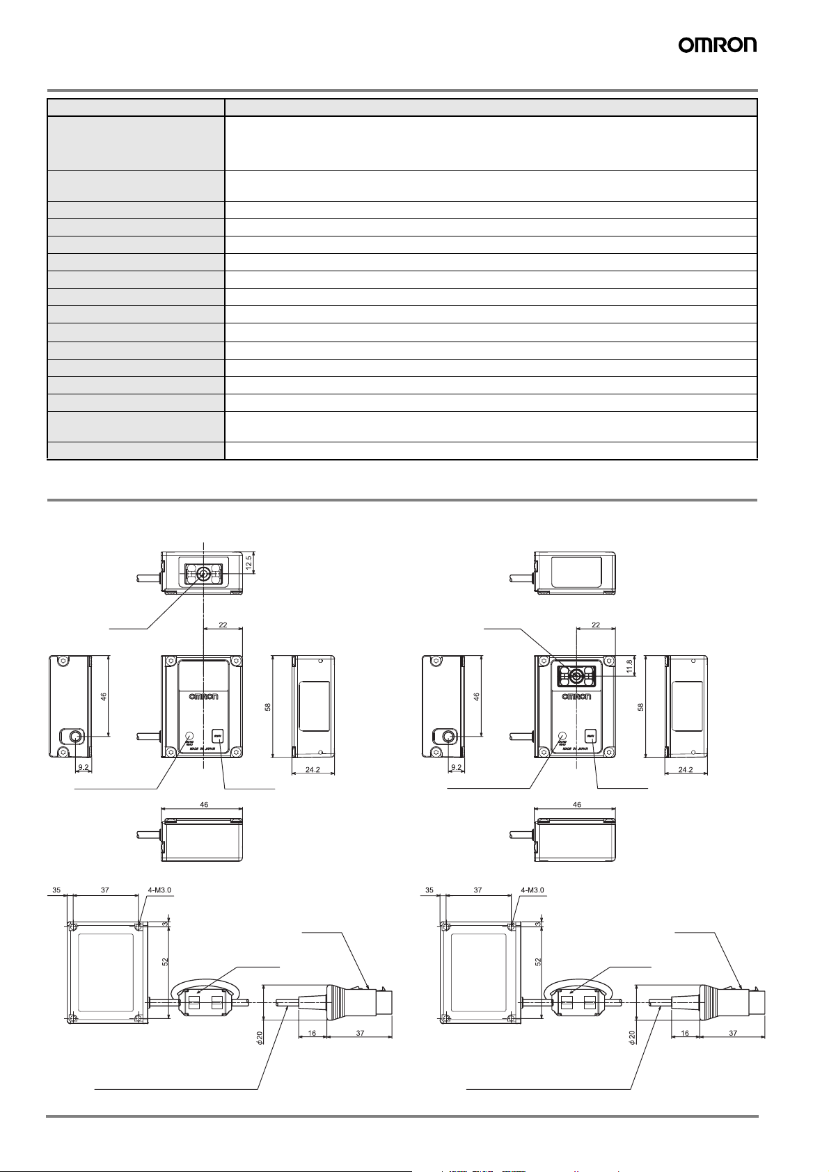
Dimensions
Multi-code reader
V400-R1CF V400-R1CS
Light axis
Read confirmation LED SCAN button
Ferrite core
Connector
Light axis
Read confirmation LED SCAN button
Connector
Ferrite core
Vinyl insulated round cord Ø3.8 10-core Black
Standard length 1.5 m
Vinyl insulated round cord Ø3.8 10-core Black
Standard length 1.5 m
Mounting bracket
2 Vision Sensors
Page 3

Ø5.4 through hole
Base
2-Ø5.4 through holes
4-Ø5.4 through holes
Cable for programmable controller connection
V509-W011
Vinyl insulated round cord Ø5.1
Reader side
DIN 8-pin connector
No. Signal
name
1 SD
2 RD
3 RS
4 CS
5 TRIG
6 -
7 SG
8 +5 V
Shield cable
Vinyl insulated round cable,
Ø4.7, 3-core (conductor section
area 0.2 mm², diameter of
insulation body: Ø1.0 mm)
2-M5 through holes
D-sub 9 pin
Pink (external trigger)
Brown (+5 V)
Blue (0 V)
Upper equipment side
D-sub 9-pin
Signal No.
name
FG 1
SD 2
RD 3
RS 4
CS 5
- 6
- 7
- 8
SG 9
(External trigger)
(+5 V)
(0 V)
3V400-R1
Page 4

Cable for connecting PC
V509-W011D
Vinyl insulated round cord Ø5.1
Reader side
DIN 8-pin connector
No. Signal
name
1 SD
2 RD
3 RS
4 CS
5 TRIG
6 -
7 SG
8 +5 V
Shielded
Shield cable
Vinyl insulated round cable,
Ø4.7, 3-core (conductor section
area 0.2 mm², diameter of
insulation body: Ø1.0 mm)
D-sub 9 pin
Pink (external trigger)
Brown (+5 V)
Blue (0 V)
Upper equipment side
D-sub 9-pin
Signal No.
name
FG 1
SD 2
RD 3
RS 4
CS 5
- 6
- 7
- 8
SG 9
Shield wire
Connector Cover
(External trigger)
(+5 V)
(0 V)
In the interest of product improvement, specifications are subject to change without notice.Cat. No. Q22E-EN-01A
OMRON EUROPE B.V.
Wegalaan 67-69,
NL-2132 JD, Hoofddorp,
The Netherlands
Phone: +31 23 568 13 00
Fax: +31 23 568 13 88
www.industrial.omron.eu
4 Vision Sensors
 Loading...