

Page 1
>F=4AB<0=D0;0334=3D<
E4AB8>= &D?30C4
Page 2

Mackie TT24 Digital Live Console Owner’s Manual Addendum v1.7
Contents
1. Introduction .................................. 3
2. Full I/O Routing ............................ 4
Using a single TT24 and a DS3232
Digital Snake .................................5
Routing Presets ............................ 6
2.1 Input Routing ................................ 8
2.2 Output Routing ........................... 14
2.3 U-Net Routing Screens .............. 28
2.4 DS3232 Routing Macros ............36
2.5 Snapshot Filtering ...................... 40
3.0 Front of House / Monitor Console
Linking ......................................... 43
3.1 Gain Compensation ................... 48
4.0 Appendix Ramblings: ................51
Need help with your new upgrade?
• Visit www.mackie.com and click Support
to fi nd: FAQs, manuals, addendums, and
other useful information.
Part No. SW0725 Rev. A 09/08
©2008 LOUD Technologies Inc. All Rights Reserved.
• Email us at: techmail@mackie.com.
• Telephone 1-800-898-3211 to speak with
one of our splendid technical support
chaps, (Monday through Friday, from 7
a.m. to 5 p.m. PST).
2
Page 3

Mackie TT24 Digital Live Console Owner’s Manual Addendum v1.7
1. Introduction
This document describes the new features available in TT24 software upgrade version 1.7.
New Features Summary
• Full Input/Output Routing via TT Control Software.
• Front of House / Monitor Linked Consoles with a single DS3232 Digital Snake.
• Support for the optional LP48 card that offers complex Loudspeaker Processing and
Insert EQ Processing.
The details of the LP48 card are not shown in this document. Please see the LP48 card
user’s guide, available from our website: www.mackie.com.
3
Page 4
Mackie TT24 Digital Live Console Owner’s Manual Addendum v1.7
2. Full I/O Routing
A full routing matrix has been added to allow complete input and output routing to and from
the input and output channels, as well as direct output routing and hardware I/O patching.
This includes analog and digital inputs and outputs. In addition, you can route U-Net signals
in and out of the console and between two U100 cards in a single console. These functions are
only accessed via the TT Control software. Routing changes cannot be done from the control
surface except by loading presets or snapshots.
The routing screens allow things such as ADAT input routing to input channels on bank 1 or
Aux Output Routing to the AES output. In addition it allows detailed routing of the signals
from each card slot, doing away with the basic bank-based routing used for the DS3232 prior
to software version 1.7.
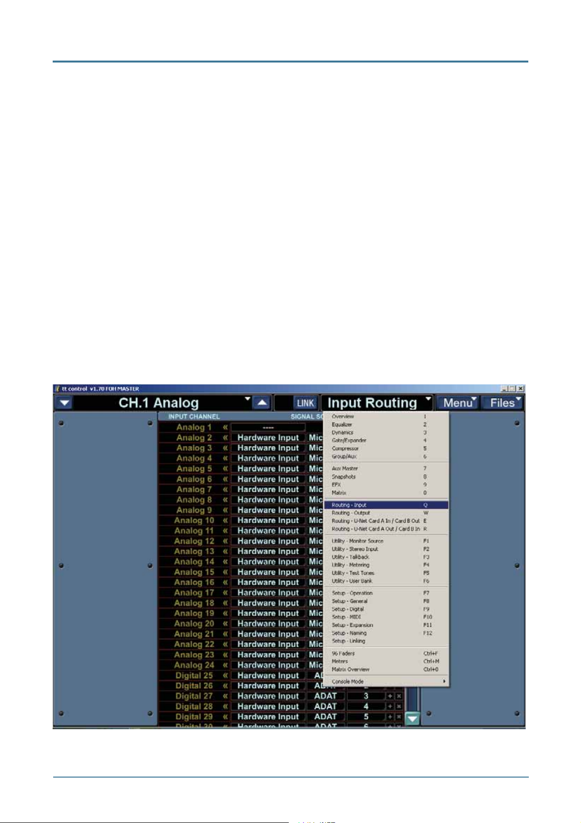
The routing screen is accessible from the central drop-down menu in the TT control PC
application. Choose one of the four new Routing options:
• Routing – Input
• Routing – Output
• Routing – U-Net Card A In / Card B Out
• Routing – U-Net Card B In / Card A Out
4
Page 5
Mackie TT24 Digital Live Console Owner’s Manual Addendum v1.7
The Input and Output routing screens are similar, and are comprised of a source and
destination list; the destinations are listed vertically on the left column followed by rows of
drop down lists to their right allowing source selection. Assign a source by selecting items
from the drop down lists from left to right This process is described in more detail in the
routing sections below.
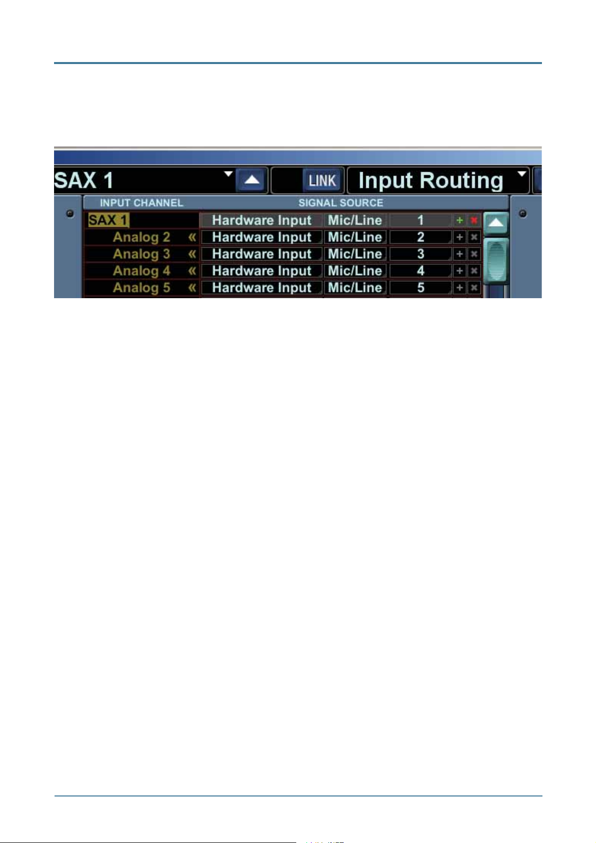
Hovering over a row will highlight the row, making navigation around the list easier. There are
more destinations than can fi t on the screen at once, so the list can be scrolled vertically using
the scroll bar along the right side or using the mouse wheel.
Additionally, each routing row has two buttons to the right side, Clear Routing (X) and
Increment Routing (+):
• Clear Routing – This clears the routing assignment for that row. It can be dragged up
or down to clear the routing on adjacent rows.
• Increment Routing – When dragged up or down, this will set the next or previous row
to the incrementally next or previous assignment, allowing you to set consecutive
assignments with ease.
NOTE: If the computer CTRL key is held while dragging, the rows will be fi lled with the
same source signal giving you a fast way to assign the same signal to multiple channels
or outputs.
Unassigned source rows will be shown as pale red dashes to indicate they are not currently
in use. Once assigned, source rows are color coded to differentiate the main source type
selected. These are described for input and output routing in the sections below.
U-Net Card Slot routing screens are slightly different. They still use the same sourcedestination method except that both the source and destination are selectable U-Net signals.
This is described in detail in U-Net Routing section on page 28.
Using a single TT24 and a DS3232 Digital Snake
If you have a single TT24 console and a DS3232 digital snake, then you need only be
concerned with the Input and Output Routing described below. There is generally no need to
look into the U-Net Card A In / Card B Out, and U-Net Card B In / Card A Out routing, unless
you are linking multiple consoles. Even then, there are factory presets that will cover most
typical systems.
5
Page 6
Mackie TT24 Digital Live Console Owner’s Manual Addendum v1.7
Routing Presets
The following sections on Input Routing, Output Routing, and U-Net Routing are shown in
some detail, with screenshots thrown in from all directions.
To make it easier for you, we have created routing presets that cover typical applications. You
may fi nd that the presets do all that you need, so you do not have to fret over the details.
Routing Presets are stored on the console and can be loaded from the console but not saved.
They can be both saved and loaded from the TT Control software. This is because routing
changes can only be made from the control software. In the TT Control software, routing
presets are saved and loaded from the File menu as usual.
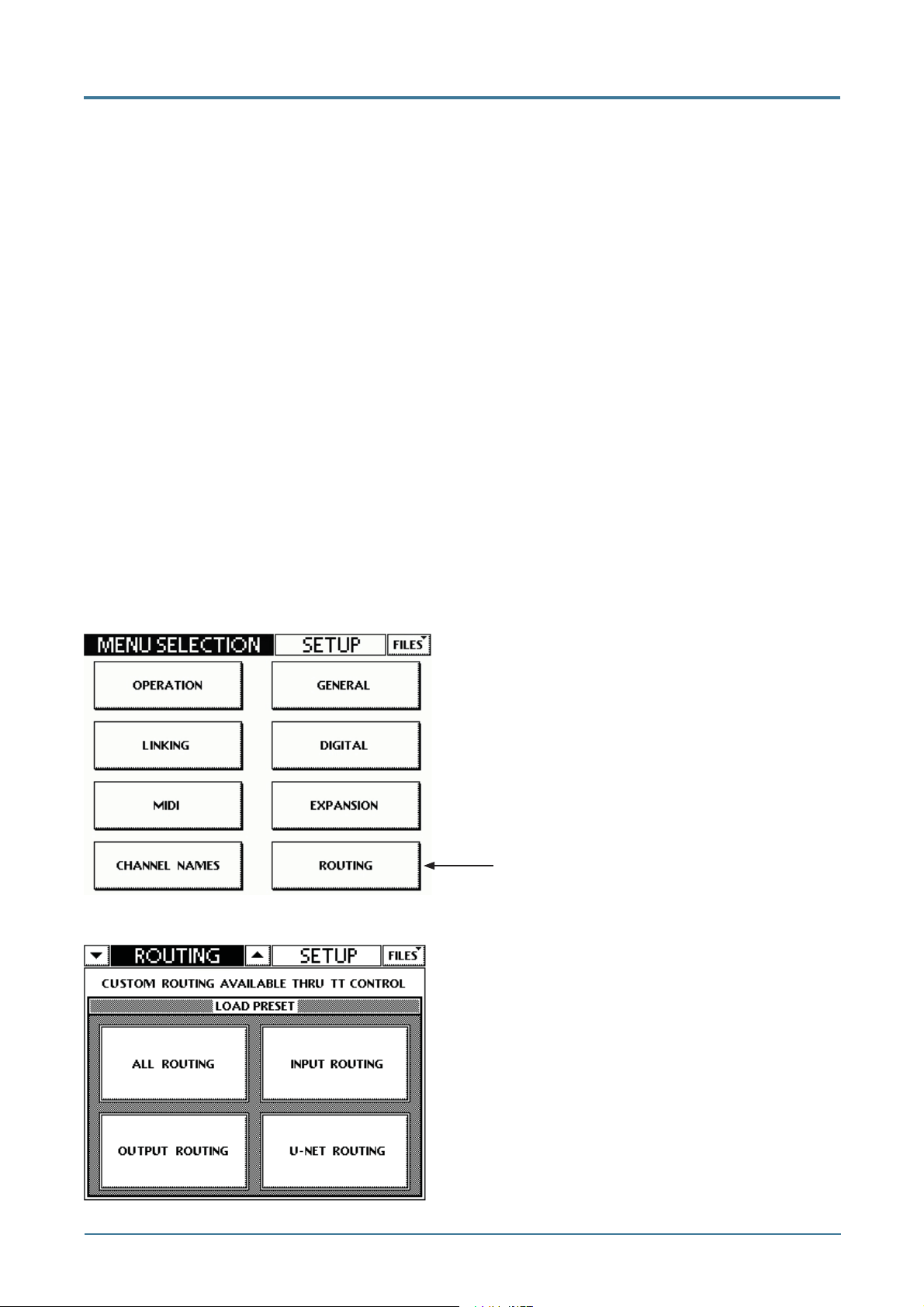
These presets are available in four types from the TT Control FILES dropdown menu, and
from the console’s routing setup screen:
• Global All Routing: Presets that affect all routing (Input, Output, and U-Net)
• Input Routing: Presets that affect the Input Routing
• Output Routing: Presets that affect the Output Routing
• U-Net Routing: Presets that affect the U-Net Routing
You can also save your own presets using TT Control, and then recall these from the console
as needed.
TT24 Console Setup Screen
Press “Routing” to bring up the Routing Setup
Screen.
Routing
TT24 Console Routing Setup Screen
Press these to bring up a list of available presets
for each one.
6
Page 7
Mackie TT24 Digital Live Console Owner’s Manual Addendum v1.7
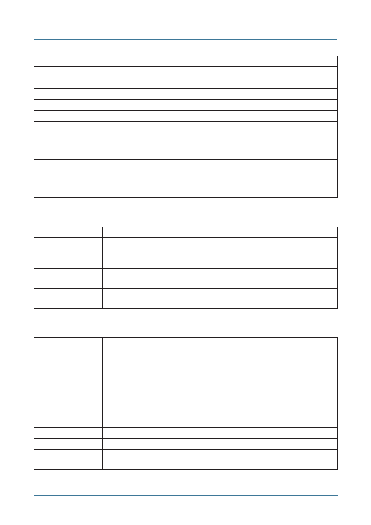
Factory Global All Routing Presets
Preset Description
Default Default input, output, and U-Net routing
Snake A Analog DS3232 connected to a U100 in card slot A, routed to the Analog bank
Snake A Digital DS3232 connected to a U100 in card slot A, routed to the Digital bank
Snake B Analog DS3232 connected to a U100 in card slot B, routed to the Analog bank
Snake B Digital DS3232 connected to a U100 in card slot B, routed to the Digital bank
MON Snake LP48 DS3232 connected to a U100 in card slot B, routed to the Analog bank
and to FOH via a second U100 in card slot A. Aux sends are routed
back to the snake. Confi gure console as MON Master on setup>linking
screen.
FOH Snake LP48 FOH console linked to MON via a U100 in card slot A. DS3232 is routed
to the Analog bank through the monitor console. An LP48 in card slot
B is routed back to the snake along with Main and Group outputs.
Confi gure console as FOH Master on setup>linking screen.
Factory Input Routing Presets
Preset Description
Default Default input routing
ADAT B1 Mic B2 ADAT inputs routed to Analog bank and Mic inputs routed to Digital
bank
Mic B1 B2 Mic inputs routed to Analog and Digital banks for independant control
of FOH and monitor mixes from a single console
ADAT B1 B2 ADAT inputs routed to Analog and Digital banks for independant
control of FOH and monitor mixes from a single console
Factory Output Routing Presets
Preset Description
Default Default output routing. Group outputs 1-8 to rear panel Group/Matrix
outputs.
Default Matrix Default output routing. Matrix outputs A-H to rear panel Group/Matrix
outputs.
Default LP48 A Default output routing. LP48 in card slot A, speaker processor outputs
1-8 to rear panel Group/Matrix outputs.
Default LP48 B Default output routing. LP48 in card slot B, speaker processor outputs
1-8 to rear panel Group/Matrix outputs.
Pre DSP ADAT Out ADAT outputs routed from the Pre DSP channel signal
ADAT In to Out ADAT inputs routed directly to the ADAT outputs for recording
Aux on Group XLR Aux 1-8 routed to the rear panel Group/Matrix XLR outputs for easy
connection to an analog snake
7
Page 8
Mackie TT24 Digital Live Console Owner’s Manual Addendum v1.7
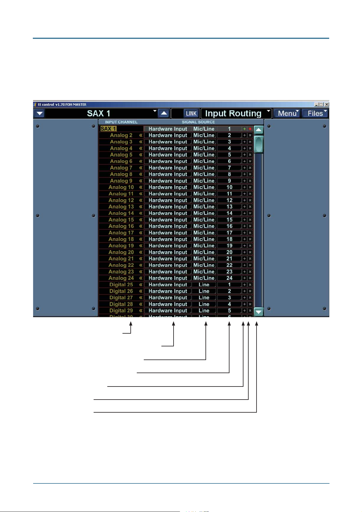
2.1 Input Routing
The Input Routing screen shows a routing list displaying Destination Input Channels down the
left column. Choose Hardware Inputs or Card Slot signals to be routed to one or more input
channels.
Destination Input Channels
Choose a Hardware Input or a Card Slot
Choose from available input types
Choose from available channels
Increment Routing (+)
Clear Routing (X)
Scroll up or down
8
Page 9
Mackie TT24 Digital Live Console Owner’s Manual Addendum v1.7
The vertical list along the left shows input channels which will be listed by their default name
and custom name (if assigned). Double clicking a channel will allow you to edit the channel
custom name. These names are in a single column with the following contents:
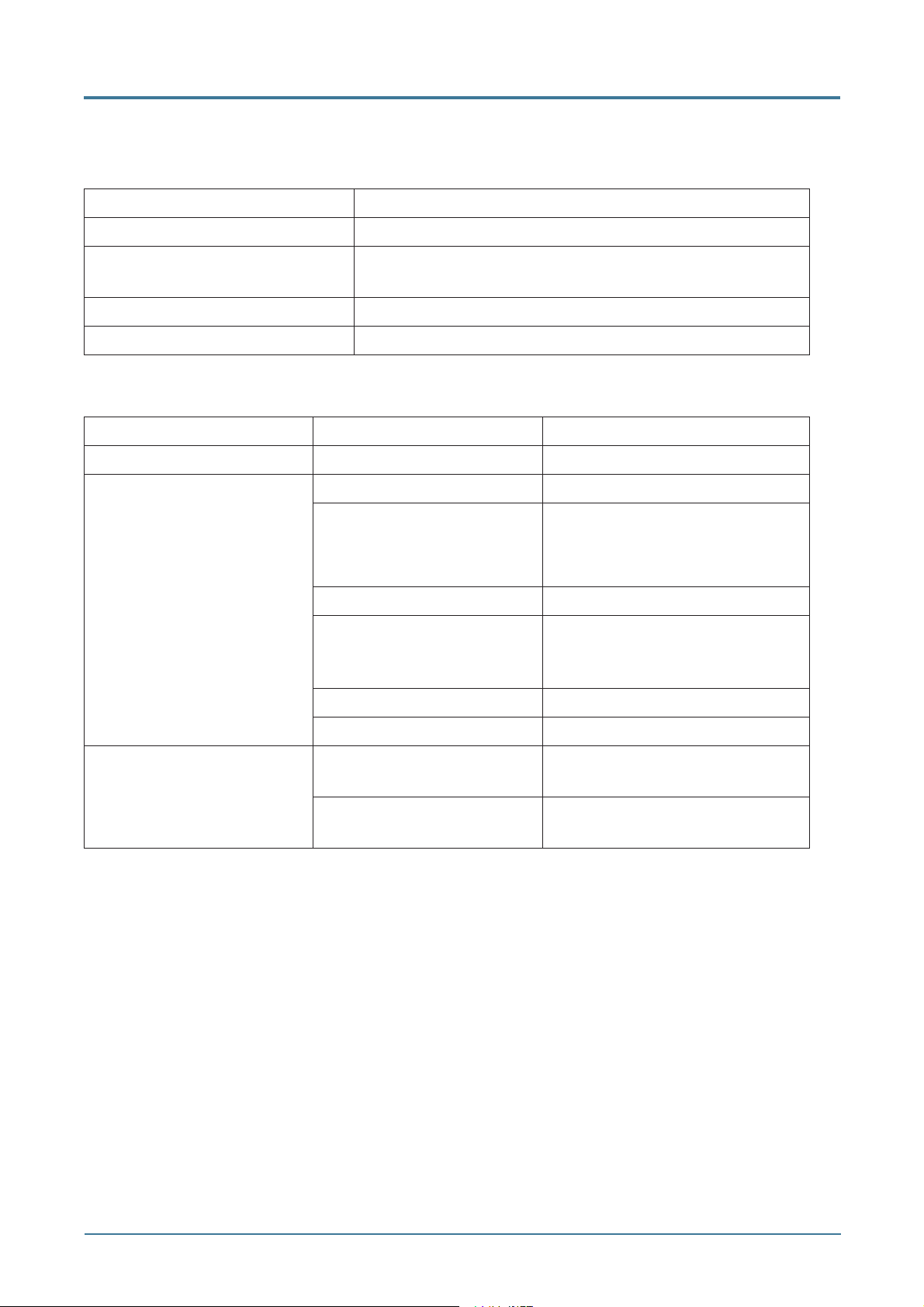
Destination Input Channels Notes
Analog 1-24 Full DSP when assigned to Analog Bank
Digital 25-48 Full DSP when assigned to Digital Bank or when
UFXII installed
Line In 1-8 EQ Only
Card 1-8 Full DSP
Input Routing Table
Signal Sources
Drop Down 1 Drop Down 2 Drop Down 3
Hardware Input Mic/Line 1-24
ADAT 1-24 (44.1 or 48k)
1-12 (88.2 or 96k)
Line 1-8
AES/SPDIF (one will be
shown depending on the
selection in setup>digital)
Tape A L-R, B L-R
Talkback In
Card Slot A - Card Type (e.g. U100) 1-32 (note LP48 shows
B - Card Type (e.g. U100) 1-32 (note LP48 shows
Each Source Row is color coded according to the selection made in the Drop Down 1 source
type:
• Hardware Input – Pale Blue (a very-faintly blue-tint of white)
• Card Slot - Pale Yellow
L-R
additional detail, see below)
additional detail, see below)
9
Page 10
Mackie TT24 Digital Live Console Owner’s Manual Addendum v1.7
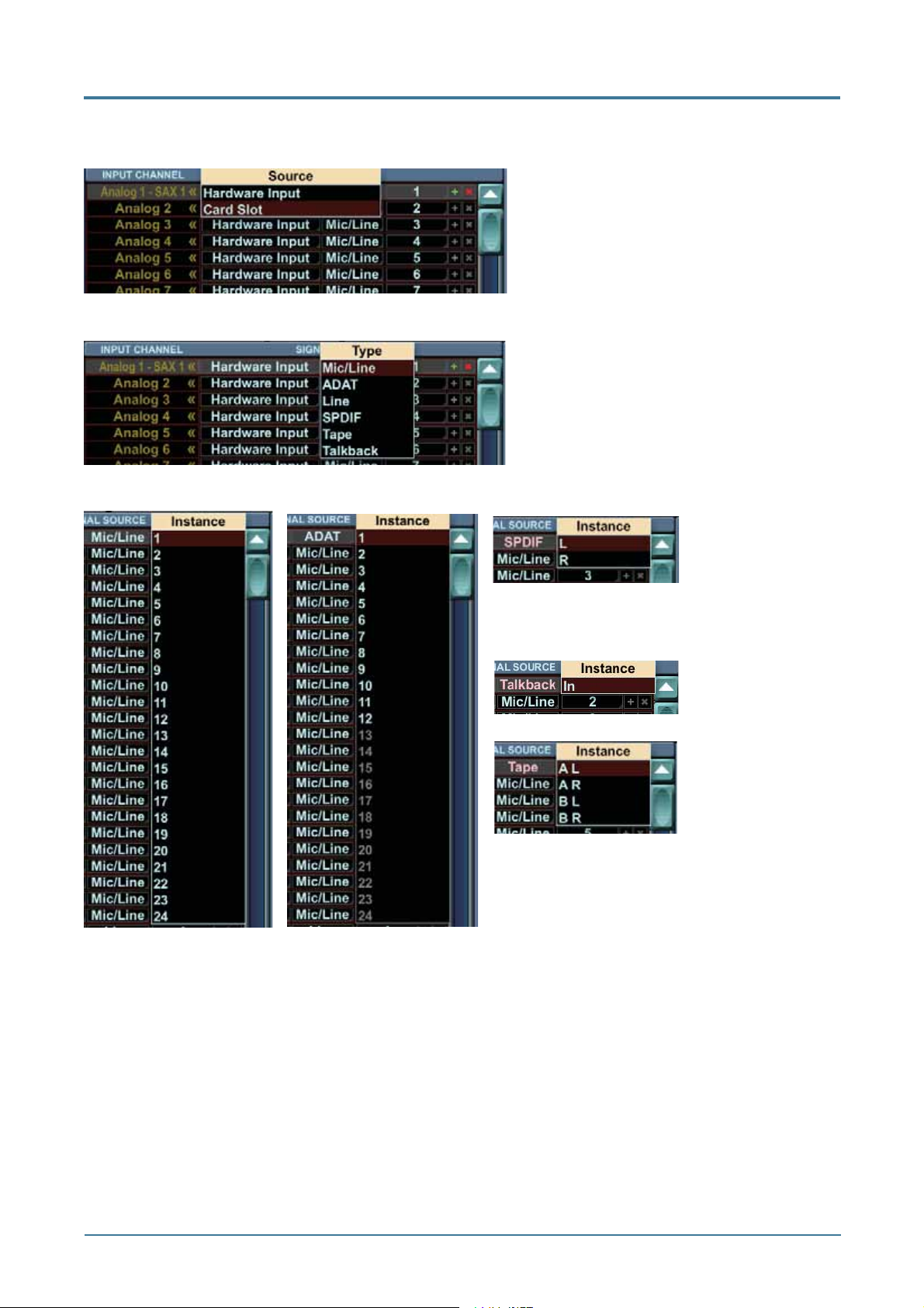
For each destination input you can select the source to be either a Hardware Input or a Card
Slot:
Choose from Hardware Input
or Card Slot
For the Hardware Input, you can choose the source type:
Choose from Mic/Line, ADAT,
Line, SPDIF, Tape, or Talkback
and choose from the “Instance” or available channels from that source type:
SPDIF has
L, R choices.
(Shows AES if
confi gured.)
Mic/Line has 1 to 24
choices
Talkback has IN
only
Tape has A L,
A R, B L and B R
choices
ADAT has 1 to 12
choices at 88.2 or 96k,
and 1-24 at 44.1 or 48k
10
Page 11
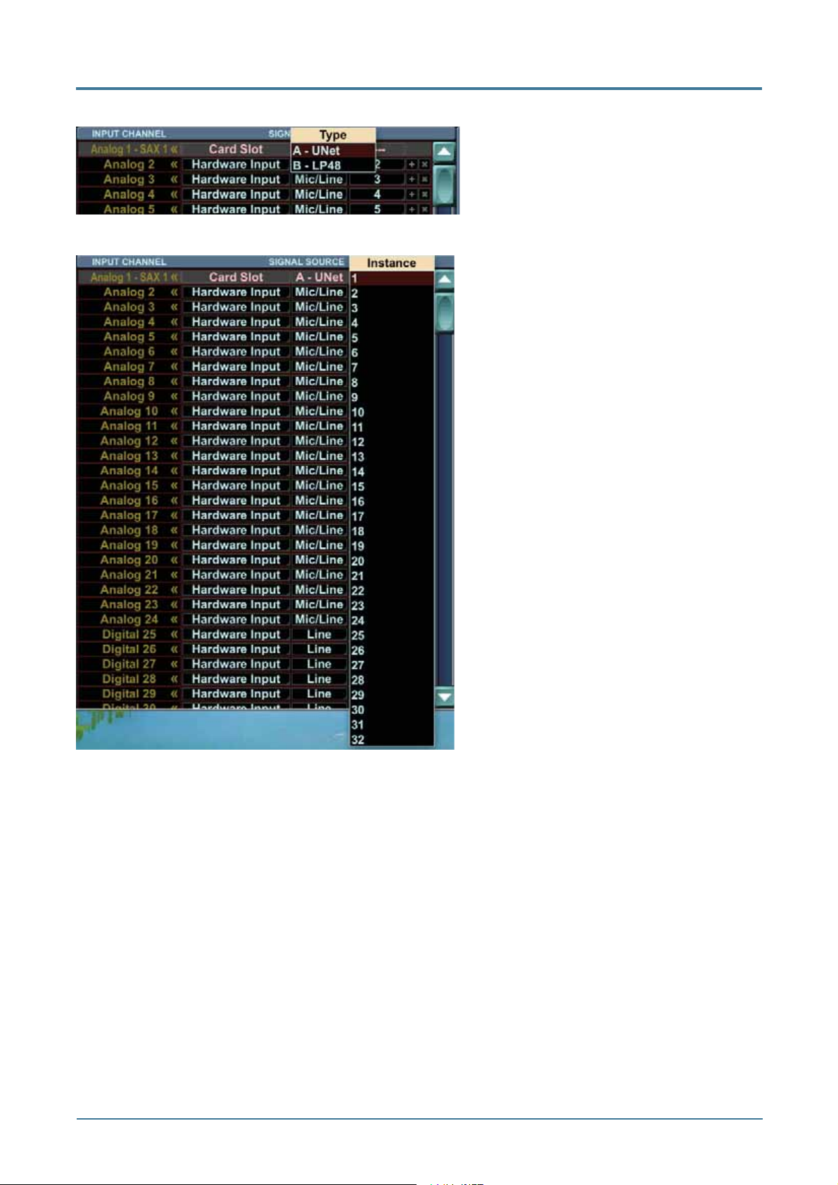
Mackie TT24 Digital Live Console Owner’s Manual Addendum v1.7
For the Card Slot, you can select from the installed cards:
Choose from UNet card or, in
this example, an LP48 card
For the UNet Card Slot, you can choose from 1 to 32:
Choose from Instances 1 to 32
The following section describes the options if you choose the LP48 card. If you don’t have
one, skip the next two pages.
11
Page 12
Mackie TT24 Digital Live Console Owner’s Manual Addendum v1.7
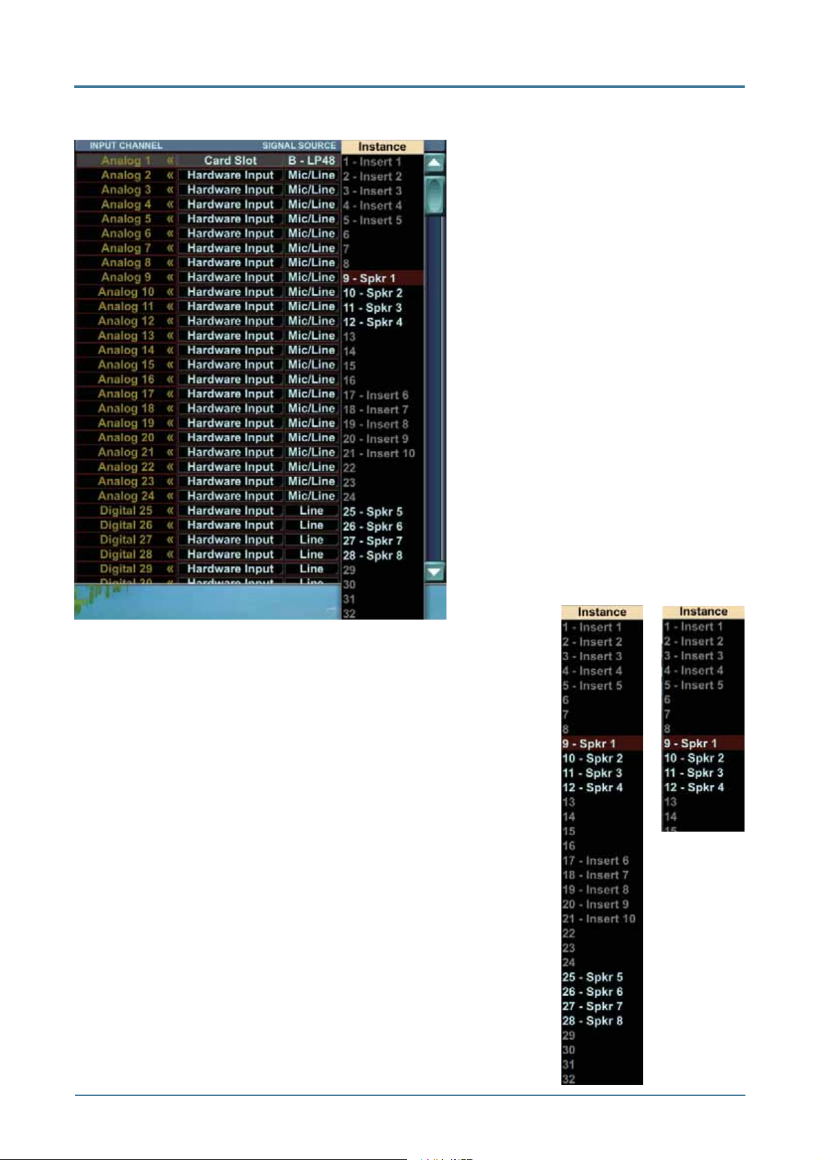
LP48 Card Routing
If you choose the LP48 card as the
source, then the available Instances
to choose from will depend on the
confi guration of the LP48 card.
The LP48 card has three different
modes of operation:
10 Insert EQs
4 x 8 Loudspeaker Processor
5 Insert EQs and 2 x 4 Loudspeaker
Processor (This is a split mode of the
above two modes.)
Insert EQs
In Insert EQ mode, the signals assigned
to the LP48 card go into the card, are
EQ’d and return to the insert point only.
They are not available for any other
routing. The output from the LP48 card
shows greyed-out labels for the inserts.
Loudspeaker Processors
In Loudspeaker Processor mode, there will either be 4 outputs (in
LP48 split mode) or 8 outputs (in 4 x 8 mode).
The available outputs from the Loudspeaker Processor are the
outputs from each crossover, such as a low, high for a two-way
crossover, low, mid, and high for a three-way, and a low, low-mid,
high-mid, and high for a four way crossover.
These can be routed to any input channel, or to any physical
output,
LP48 in
Split mode
LP48
in 4 x 8
mode
12
Page 13
Mackie TT24 Digital Live Console Owner’s Manual Addendum v1.7
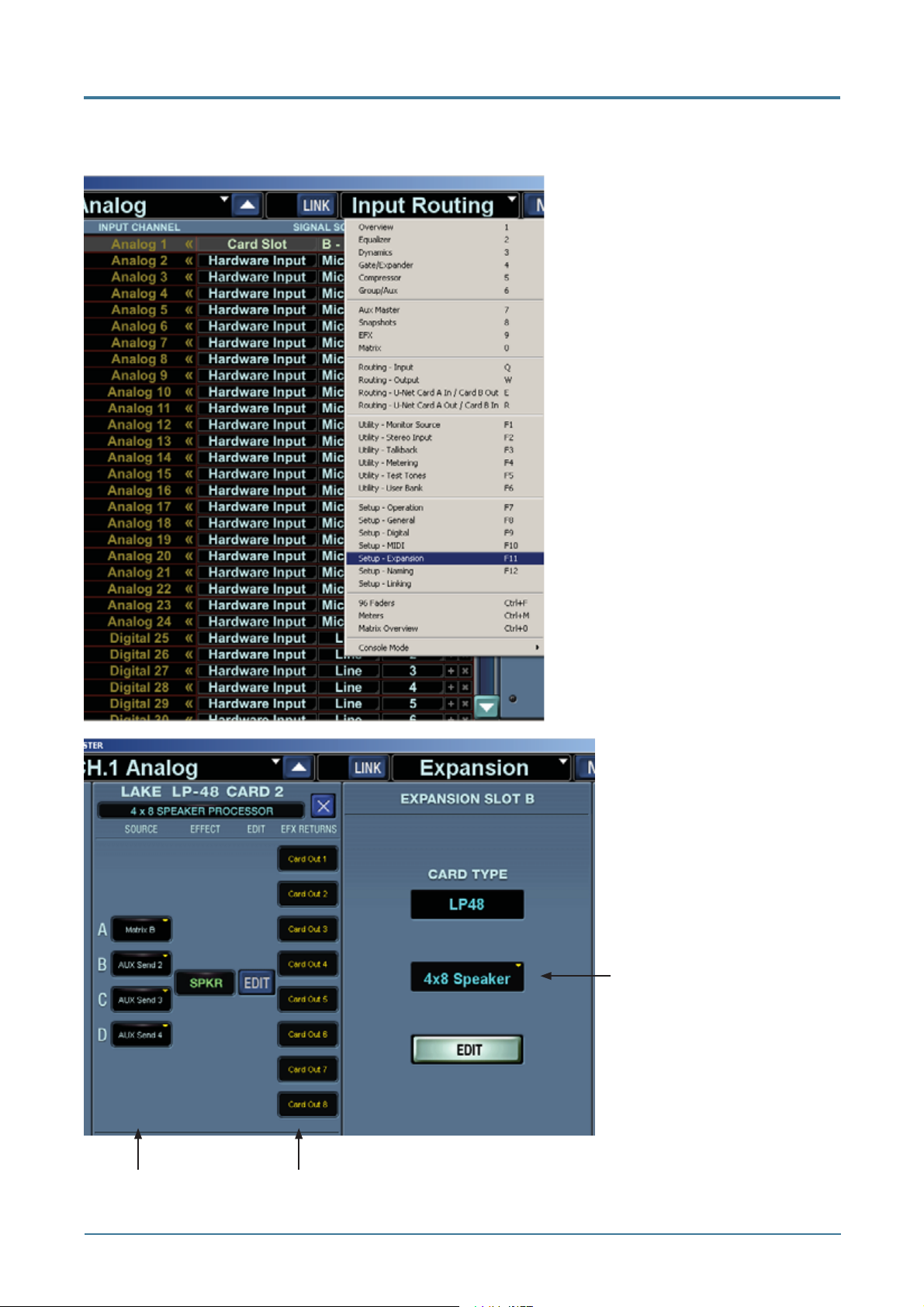
Changing the mode of the LP48 Card
To change the mode of the LP48 card use the Expansion menu, or press F11:
Select Mode here
Crossover Outputs (4 x 8 mode shown)Select Inputs here
13
Page 14
Mackie TT24 Digital Live Console Owner’s Manual Addendum v1.7
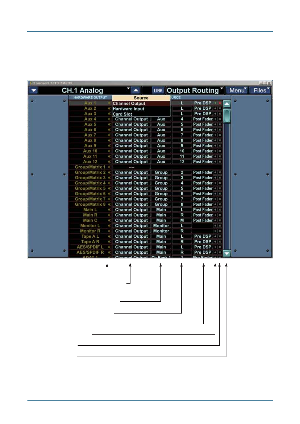
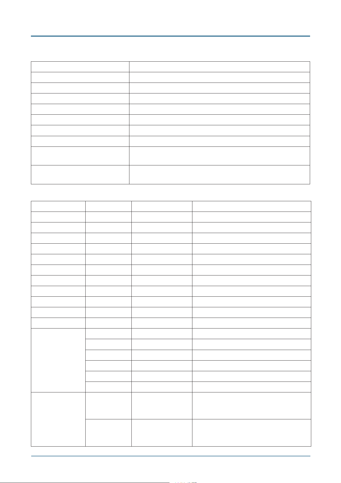
2.2 Output Routing
The Output Routing screen shows a routing list displaying Destination Hardware Outputs
down in the left column. Choose from the Channel Outputs, Hardware Inputs, or Card Slot
signals to be routed to one or more hardware outputs.
Destination Output Channels
Choose a Channel Output, Hardware
Input or Card Slot
Choose from available signal types
Choose from available channels
Choose from Pre or Post options
Increment Routing (+)
Clear Routing (X)
Scroll up or down
14
Page 15
Mackie TT24 Digital Live Console Owner’s Manual Addendum v1.7
The vertical list along the left shows hardware outputs. These names appear in a single
column with the following contents:
Destination Hardware Outputs Notes
Aux 1-12
Group/Matrix 1-8
Main L, R, C
Monitor L, R, C
Tape A L, R
AES/SPDIF L, R
ADAT 1-24
Card A – Card Name 1-32 The card name is replaced with the name of the card in
the slot if one is present
Card B – Card Name 1-32 The card name is replaced with the name of the card in
the slot if one is present
Choose sources for each output by selecting an item from each of four drop down lists:
Signal Sources
Drop Down 1 Drop Down 2 Drop Down 3 Drop Down 4
Channel Output Main L, R, C (or M) Pre DSP, Post Fader
Aux 1-12 Pre DSP, Post Fader
Group 1-8 Post Fader
Matrix A-H Pre Delay, Post Delay
Monitor L-R
Ch Bank 1 1-24 Pre DSP, Pre Fader
Ch Bank 2 25-48 Pre DSP, Pre Fader
Ch Line 1-8 Pre DSP, Pre Fader
Ch FX 1 L-4 R Pre Fader
Ch Card 1-8 Pre DSP, Pre Fader
Hardware Input Mic/Line 1-24 -
ADAT 1-24 (44.1 or 48k) 1-12 if sample rate is 88.2 or 96k
Line 1-8 AES/SPDIF L-R AES or SPDIF, whichever is installed
Tape A L-R, B L-R Talkback In
Card Slot A - Card
Type (e.g.
U100)
B - Card
Type (e.g.
U100)
1-32 (note LP48
shows additional
detail, see below)
1-32 (note LP48
shows additional
detail, see below)
15
-
-
Page 16
Mackie TT24 Digital Live Console Owner’s Manual Addendum v1.7
Each source row is faintly color-coded according to the selection made in the Drop Down 1
source type:
• Channel Output - Pale Blue-ish white
• Hardware Input – Pale Orange
• Card Slot - Pale Yellow
Output Routing Examples
For each destination output, you can select the source to be either a Channel Output,
Hardware Input, or a Card Slot.
Choose from Channel Output,
Hardware Input or Card Slot
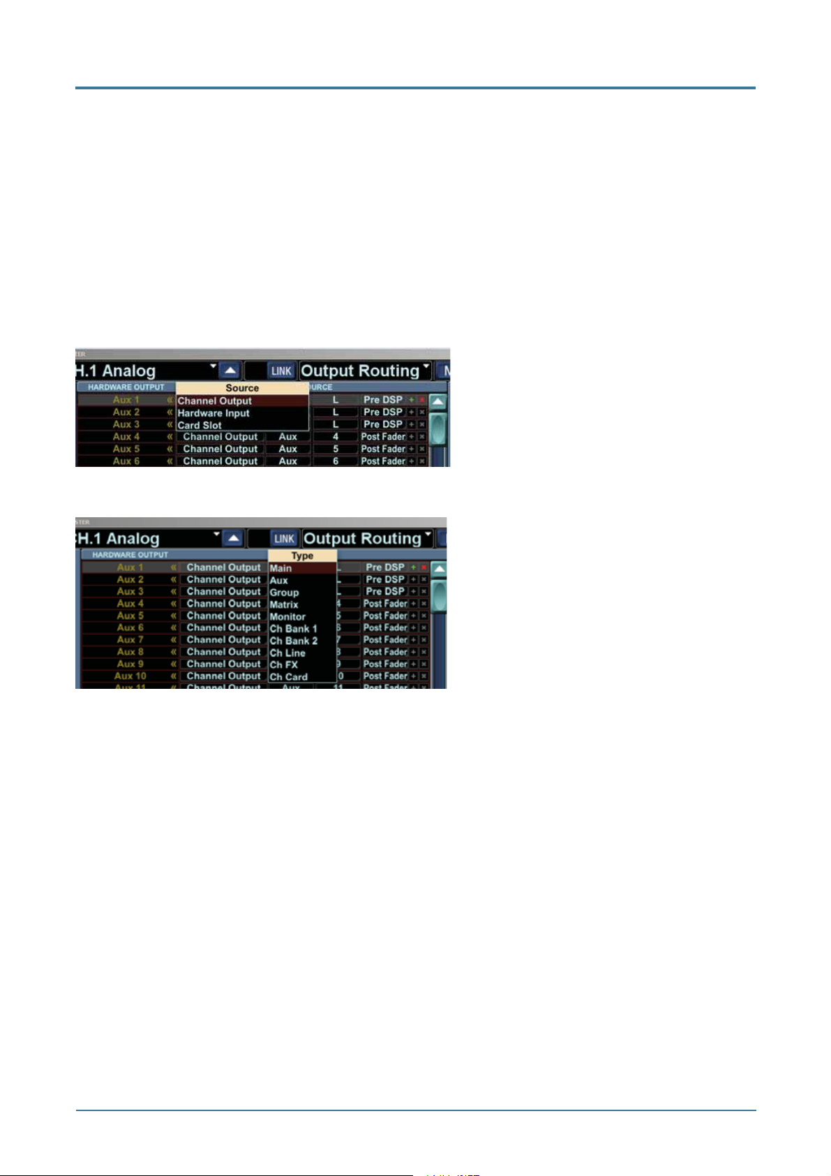
Channel Outputs
If you choose a Channel Output, you
can select from the following Types:
Choose from Main, Aux, Group,
Matrix, Monitor, Ch Bank 1, Ch Bank
2, Ch Line, Ch FX, and Ch Card. Each
of these has other options, shown on
the next few pages of this guide.
16
Page 17

Mackie TT24 Digital Live Console Owner’s Manual Addendum v1.7
Channel Outputs: Main
If you choose Main from the channel output options, you can select from L, R or M, and each
can be Pre DSP or Post Fader:
Choose Main
Choose L, R, and M (or L, R,
C)*
Choose Pre DSP or Post
Fader
* Instead of L, R, and M, it could be L, R, and C depending upon the setting in the Operations
menu:
LCR
L/R + Mono
17
Page 18

Mackie TT24 Digital Live Console Owner’s Manual Addendum v1.7
Channel Outputs: Aux
Aux: Choices 1 to 12, and
each can be Pre DSP or Post
Fader:
Channel Outputs: Group
Group: Choices 1 to 8,
Post Fader. Note that
these Group options will
be greyed-out if Matrix is
enabled in the console.
Channel Outputs: Matrix
Matrix: Choices A to H,
and each can be Pre Delay
or Post Delay: Note that
these Matrix options will
be greyed-out if Group is
enabled in the console.
Note: The Group/Matrix hardware outputs are changed automatically when enabling or
disabling the matrix if they are set to the defaults. If they have been changed to a custom
confi guration, they will not be changed as the matrix is enabled or disabled.
18
Page 19

Mackie TT24 Digital Live Console Owner’s Manual Addendum v1.7
Channel Outputs: Monitor
Monitor: Choices L and R
Channel Outputs: Channel Bank 1
Channel Bank 1: Choices 1 to 24.
Each can be Pre DSP or Pre Fader:
19
Page 20

Mackie TT24 Digital Live Console Owner’s Manual Addendum v1.7
Channel Outputs: Channel Bank 2
Channel Bank 2: Choices 25 to 48.
Each can be Pre DSP or Pre Fader:
Channel Outputs: Channel Line
Channel Outputs: Channel FX
Channel Line: Choices 1 to 8.
Each can be Pre DSP or Pre Fader:
Channel FX: Choices 1 L, 1 R, 2 L,
2 R, 3 L, 3 R, and 4 L, and 4 R.
Each is Pre Fader.
20
Page 21

Mackie TT24 Digital Live Console Owner’s Manual Addendum v1.7
Channel Outputs: Channel Card
Channel Card: Choices 1 to 8.
Each can be Pre DSP or Pre Fader:
Hardware Input
If you choose a Hardware Input instead of a Channel Output:
Hardware Input: Choices are
Mic/Line, ADAT, Line, SPDIF,
Tape, and Talkback.
Each has its own menus, and
these are described in the
next few pages:
21
Page 22

Mackie TT24 Digital Live Console Owner’s Manual Addendum v1.7
Hardware Input: Mic/Line
Mic/Line: Choices 1 to 24.
Hardware Input: ADAT
ADAT: Choices 1 to 12 if the sample rate
is 88.2 or 96k, and 1 to 24 if the sample
rate is 44.1 or 48k.
See ADAT card notes on page 27 for
more details.
22
Page 23

Mackie TT24 Digital Live Console Owner’s Manual Addendum v1.7
Hardware Input: Line
Line: Choices 1 to 8.
Hardware Input: SPDIF
SPDIF: Choices L, R.
Hardware Input: Tape
Hardware Input: Talkback
Tape: A L, A R, B L, B R.
Talkback: In.
23
Page 24

Mackie TT24 Digital Live Console Owner’s Manual Addendum v1.7
Card Slot
If you choose a Card Slot, you can select from the available cards:
Card Slot: Here we can choose between
the LP48 card or the UNet card.
Card Slot: UNet Card
UNet card: Choices 1 to 32.
24
Page 25

Mackie TT24 Digital Live Console Owner’s Manual Addendum v1.7
Card Slot: LP48 Card
LP48 card: If the LP48 card has been
confi gured as a 4x8 Loudspeaker
Processor, there will be 8 outputs
available as shown. These represent the
outputs of the various crossovers of the
LP48. The Insert EQs are greyed-out
and not available for selection.
Note that the inputs to the LP48 card
are chosen in the Setup>Expansion
screen.
LP48 card: If the LP48 card has been
confi gured as a 2x4 Loudspeaker
Processor, with 5 Insert EQs, there will
be 4 outputs available as shown. These
represent the outputs of the various
crossovers. The Insert EQs are greyedout and not available for selection. (The
EQ’d signals return to the insert point
they came from.)
See additional details described in the
input routing screen on page 12.
25
Page 26

Mackie TT24 Digital Live Console Owner’s Manual Addendum v1.7
Card Slot Routing Notes
Routing to and from I/O cards is handled by signal paths. The TT24 supports a maximum of
32 input and output signal paths to/from each card slot. But, some cards (LP48) have less
then 32 inputs/outputs. Routing signals to these cards on these higher number signal paths
will have no effect, but because the routing is stored in the console, we support routing to all
signal path numbers no matter which card is installed.
If a card is installed that does not support all 32 signal paths, the unused signal path numbers
are shown in grey indicating that they are still routable but that they are unused. Routing
to/from these greyed out signal paths will therefore have no effect although you can still
make the routing connections. Similarly, if the console does not have a card in slot A and/or
B, the signal paths for the entire card slot will appear in grey again indicating that they are
still routable although no audio will pass. Finally, some cards (LP48) have multiple operating
modes and each mode may have a different number of supported signal paths. Therefore as
the mode is changed, the number of available versus greyed-out source and destination signal
path numbers will change.
The above method allows for cards to be changed while keeping routings intact. Existing
routings will just use the corresponding input/output from the newly added card. This gives
consistent and reliable operation that you can easily understand and change when a new card
is installed and you hear audio you are not expecting.
This operation is described for each card type and mode combination in the table below; note
that each card slot is handled independently:
Card
Type
UFXII Channel 25-48 DSP None (routing done
LP48 4 x 8 Speaker
ADAT 44.1/48 kHz None, see ADAT table
Mode Available Card Signal
Path Sources
automatically)
9-12 (Spkr 1-4)
Processor
2 x 4 Speaker
Processor / 10 Insert
EQ
10 Insert EQ None (routing done on
88.2/96 kHz None, see ADAT table
25-28 (Spkr 5-8)
9-12 (Spkr 1-4) None (routing done on
the setup>Expansion
screen)
below
below
Available Card Signal
Path Destinations
None (routing done
automatically)
None (routing done on
the Setup>Expansion
screen)
the Setup>Expansion
screen)
None (routing done on
the Setup>Expansion
screen)
None, see ADAT table
below
None, see ADAT table
below
U100 FOH/MON/DS3232
U-Net Routing
Master/Slave Console
Linking
32 32
None None
26
Page 27

Mackie TT24 Digital Live Console Owner’s Manual Addendum v1.7
ADAT Notes
The available built-in ADAT I/O and an ADAT card interact with sample rate changes. Because
the channel-count halves for ADAT at the 88.2/96k rating, special consideration must be
taken.
At 88.2/96k, half of the built in ADAT I/O (sources and destinations) will be unavailable and
will be shown with the destination number in the output routing table greyed out. Similarly,
the input and output routing will also indicate half of the sources are unavailable at 88.2/96k
but still routable. Again, these will still be assignable and will resume functionality if you
changes back to 44.1/48k. Adding an ADAT card will allow all the sources and destinations to
be available at all sample rates. The card automatically routes the inputs and outputs for the
additional I/O. It therefore is not directly routable.
There are three supported ADAT related confi gurations: no cards, 1 card in Slot A, and 1
card in Slot B. Two ADAT cards are not supported at this time. The various scenarios are
summarized in this table:
ADAT Mode Built In ADAT I/O
Built-In 44.1/48 kHz 1-24
88.2/96 kHz 1-12
Built-In and Card A 44.1/48 kHz 1-24
88.2/96 kHz 1-24
Built-In and Card B 44.1/48 kHz 1-24
88.2/96 kHz 1-24
27
Page 28

Mackie TT24 Digital Live Console Owner’s Manual Addendum v1.7
2.3 U-Net Routing Screens
If you are using a single TT24 and a DS3232, then the input and output routing screens allow
you to choose the desired input and output routing. These two screens are generally all that
you will need.
DS3232
Digital
Snake
For a single TT24 console, the input and output
screens allow you to confi gure all the TT24
console inputs and outputs, including the U100
card. For example, the U100 card in slot A can
receive the inputs from your digital snake, and
send receive
32 32
U100
Card A
LP48
Card B
TT24
Chassis
it can also send the LP48 card loudspeaker
crossover outputs to the snake and off to your
power amplifi ers.
If you have two TT24 consoles and wish to link them together, you can use the U-Net routing
screens. These are required to pass signals between the two U-Net cards. Using the UNet routing allows the two TT24 consoles to share the digital snake and other inputs. For
example, microphones connected to the snake can pass their signals to both consoles.
DS3232
Digital
Snake
U100
Card of
another
TT24
send receive send receive
32 32 32 32
U100
Card A
U100
Card B
TT24
Chassis
You must manually route up to 32 signals to and from each card using the Output Routing
screen as described previously. You must also choose up to 32 signals to route-into and
another 32 to route-out of the card slot signal paths themselves. This is done using the U-Net
Routing screens. Because this can be labor intensive, many common setups are provided as
routing presets. See Routing Presets on page 6.
Two U-Net Routing screens are available: one to route from Card Slot A to B and one to route
from Card Slot B to A. Routing from Card Slot A to B involves choosing up to 32 U-Net signals
to receive at the input of card A. You can then choose to route these signals directly back out
of U-Net card B. This complements the Card A to B patching that can be done in the Output
Routing screen. Routing from Card B to A is essentially the inverse. Otherwise, the two
screens are the same. If one or the other U-Net cards is not installed, the routings will appear
greyed out, but they can still be viewed and edited allowing confi guration of the network in
advance without a U100 card.
28
Page 29

Mackie TT24 Digital Live Console Owner’s Manual Addendum v1.7
Each Routing screen is in two parts: receive and send. For example, the UNetAB Routing
screen shows:
• U100 Slot A: Receive
• U100 Slot B: Send
In the Slot A Receive section, you can select the particular signals that you want to come into
the Slot A Card either from a DS3232 or another TT24.
In the Slot B Send area, you can select the output signals available from the Card Slot B
Sends.
Each U-Net Routing screen has a column of fi elds to select the 32 receive signals, and
another one for the 32 send signals. An arrow at the top helps to illustrate the send/return
relationship. Double clicking on this arrow is a shortcut to switch between the two U-Net
routing screens. For each send or receive signal path, fi ve drop down menus are necessary to
defi ne a U-Net signal:
• Product (DS3232 or TT24)
• Instance
• Signal Type
• Number
• Node
Product
Instance
Signal Type
Number
Node
Double-click the arrow to see the next Routing screen
Product
Instance
Signal
Number
Node
Increment Routing (+)
Clear Routing (X)
U100 Slot A: RECEIVE U100 Slot B: SEND
Increment Routing (+)
Clear Routing (X)
Scroll up or down
Card signals 1 to 32
29
Page 30

Mackie TT24 Digital Live Console Owner’s Manual Addendum v1.7
If you choose a U-Net Send signal that originates in the console (e.g. TT FOH Master Aux 1),
the corresponding connection will also be automatically made in the Output Routing screen.
The inverse is also true: if you route a signal to a Card Slot output signal path on the Output
Routing screen, the corresponding signal will automatically be chosen in the appropriate UNet Routing screen.
If you choose a U-Net Send signal that does not originate in the console (e.g. DS3232
Input 1), it will automatically be requested at the opposite card’s U-Net Receive input. The
corresponding Output Routing screen selection routing one card to the other will also be
made.
Selection Examples
The following example screens show the selections available for U100 Slot A: Receive. The
same choices are available on Slot A or B, Send or Receive.
DS3232 on a Card Slot RECEIVE
Select DS3232.
Select 1.
Select Input.
Select Instance from 1 to 32.
All are Pre Fader
So, what have we done?
We have set the U100 Slot A channel 1 so it will receive only the DS3232 signal
that corresponds to our selections. The card is ready for the input of a DS3232
signal 1 on Card A receive channel 1. The card inputs can now be routed to
input channels.
30
Page 31

Mackie TT24 Digital Live Console Owner’s Manual Addendum v1.7
DS3232 on a Card Slot SEND
This example shows the U100 Slot B: SEND set up in exactly the same way as shown for the
Slot A: RECEIVE on the previous page:
DS3232
1
Input
1 to 32
Pre-Fader
Here we have set the U100 Slot B SEND channel 1 so it will send only the DS3232 signal that
corresponds to our selections. Card B Send is ready to send DS3232 signals.
You will notice that when you select the DS3232 as your send, the U100 Slot A: RECEIVE will
also change to the same selection. This auto-fi lling-in of the receive side only happens if you
are sending a signal that does not originate from the host console. The card is getting ready to
send something it doesn’t have, so it gets ready to fi nd and receive it fi rst.
If, in the above example, we now set up to send a TT24 FOH Master signal, the receive side
will not change:
TT24 on a Card Slot RECEIVE
Select TT24, and the choices are:
FOH Master
FOH Slave
MON Master
MON Slave
Each of these selections has extra menus as
shown in the next few pages of this guide:
31
Page 32

Mackie TT24 Digital Live Console Owner’s Manual Addendum v1.7
Select FOH Master, and the choices are:
Out Main, Out Aux, Out Group, Out Matrix,
Out Monitor, Ch Bank 1, Ch Bank 2, Ch Line,
Ch FX, Ch Card, In Mic/Line, In ADAT, In
Line, In AES/SPDIF, In Tape, In Talkback,
Card A and Card B.
Main: Choose L, R, C
(or M)
Aux: Choose 1 to 12
Group: Choose 1 to 8
The choices are:
Pre DSP or Post Fader
The choices are:
Pre DSP or Post Fader
Matrix: Choose A to H The choices are:
Pre Delay or Post Delay
32
Page 33

Mackie TT24 Digital Live Console Owner’s Manual Addendum v1.7
Monitor: Choices are L or R.
Ch Bank 1: Choices are
1 to 24 (Pre Fader)
Ch Bank 2: Choices are
25 to 48 (Pre Fader)
Ch Line:
Choices are 1 to 8
(Pre Fader)
In Mic/Line:
Choices are 1 to 24
(Input)
Ch FX:
Choices are 1L, 1R, 2L, 2R, 3L, 3R, 4L and
4R (Pre Fader)
33
Page 34

Mackie TT24 Digital Live Console Owner’s Manual Addendum v1.7
ADAT:
Choices are 1 to 24
(Input)
In Line:
Choices are 1 to 8
(Input)
In AES/SPDIF:
Choices are L, R (Input)
Talkback: In (Input)
In Tape:
Choices are A L, A R, B L, or B R
(Input)
Card A:
Choices are 1 to 32
Card B:
Choices are 1 to 32
34
Page 35

Mackie TT24 Digital Live Console Owner’s Manual Addendum v1.7
TT24 on a Card Slot SEND
This example shows the U100 Slot B: SEND set up to send the FOH Master main outputs.
As these signals originate in the host console (set to FOH Master) setting the sends does not
affect the receive settings (here the dashes show no assignment).
TT24
FOH Master
Ch Bank 11 to 32
1-24
Pre Fader
U100 Slot B: SEND
If we change the Send signals to MON Master, these signals do not originate on the host
console (confi gured as a FOH Master), so they must be found. In this case, the Receives have
all been set automatically to the MON Master settings.
MON MasterMON Master
35
Page 36

Mackie TT24 Digital Live Console Owner’s Manual Addendum v1.7
2.4 DS3232 Routing Macros
Because you can now use input routing to freely assign any hardware input to any channel,
you can assign some snake signals to bank 1, some to bank 2, and still others to bank 3. This
can be done per channel as previously described. Additionally, three macro buttons makes
quick routing possible for all snake inputs.
On the Expansion screen with a DS3232 present, if ANALOG
is pressed, the analog snake inputs are automatically
assigned in the Input Routing screen to the analog inputs:
Analog
In the Input Routing screen, the analog
inputs are automatically fi lled with the card
slot U-Net card inputs.
In the Expansion screen, if DIGITAL is pressed, the digital
snake inputs are automatically assigned in the Input
Routing screen to the digital inputs as shown on the next
page of this guide.
Digital
36
Page 37

Mackie TT24 Digital Live Console Owner’s Manual Addendum v1.7
In the Input Routing screen, the digital inputs
are automatically fi lled with the card slot UNet card inputs.
In the Expansion screen, if NONE is selected, then no
Snake inputs are automatically assigned to the U-Net
cards:
None
37
Page 38

Mackie TT24 Digital Live Console Owner’s Manual Addendum v1.7
DS3232 Routing Macros output routing
In the Expansion screen, if
DIGITAL or ANALOG are pressed,
the outputs to the digital snake
are automatically assigned in the
Output Routing screen.
The outputs to the snake are:
Auxes 1 to 12, post fader.
Groups 1 to 8, or Matrix instead if
assigned.
LP48 outputs (if LP48 card present)
or Auxes again (if LP48 not
present). Some or all of the LP48
outputs may be greyed-out and
so not available, depending on the
mode of the LP48 card.
Talkback.
Main outputs L, R, and M (or C).
38
Page 39

Mackie TT24 Digital Live Console Owner’s Manual Addendum v1.7
Additional Controls
Snake assigned to channel
If a snake is assigned to an input channel, the following additional controls are shown for the
channel overview:
Mic Pre Gain
Pad
48V
Snake Digital Trim (note that this is a different parameter
than the digital trim shown when a snake is not assigned –
see gain compensation in section 3.1 or more information)
Snake not assigned to channel
If a single snake input is routed to more then one channel, then all channels fed by the snake
input will see and have control of the same mic pre. This is because there is only a single mic
pre, pad, and +48V for each input in the snake, and it therefore will affect all channels fed by
that snake input. All snake digital trims are independent per channel.
39
Page 40

Mackie TT24 Digital Live Console Owner’s Manual Addendum v1.7
2.5 Snapshot Filtering
Routing
Routing is saved in a snapshot and is fi ltered with three new “routing” fi lter buttons:
• Inputs – Filters out all Input routing changes
• Outputs – Filters out all Output routing changes
• U-Net – Filters out all U-Net (A to B and B to A) routing changes.
Unless fi ltered, loading a snapshot will change the entire console routing to that stored in
the snapshot. When fi ltered, a snapshot will not recall any corresponding routing changes.
Note that when doing U-Net routing, it usually makes sense to either enable or disable all
three routing buttons at once since U-Net routing generally requires input and output routing
changes as well. Two other (non-routing) fi lters are also added: LP48 and Mic Pre, and you
can fi lter the card channels on Bank 3.
New Snapshot Filters
Snapshot
Filtering
Example
40
Page 41

Mackie TT24 Digital Live Console Owner’s Manual Addendum v1.7
Snapshot Filtering – Mic Pre
Snapshot fi ltering has a new fi lter added called MIC PRE. The following parameters will not be
recalled when this fi lter is enabled:
• Snake Gain
• Snake Pad
• Snake 48v
• Digital Trim (previously fi ltered by Others and available even if a snake is not
connected)
• Polarity Inverse (previously fi ltered by Others and available even if a snake is not
connected)
41
Page 42

Mackie TT24 Digital Live Console Owner’s Manual Addendum v1.7
Snapshot Filtering – LP48 card
Snapshot fi ltering has a new fi lter added called LP48. All the parameters of the LP48 card and
the card setup found on Setup>Expansion will not be recalled when this fi lter is enabled:
LP48 Snapshot Filter
42
Page 43

Mackie TT24 Digital Live Console Owner’s Manual Addendum v1.7
3.0 Front of House / Monitor Console Linking
Front of House / Monitor Console Linking allows the support of two TT24s (one in front of
house master position and the other in monitor master position) and one DS3232.
The Snake is connected to a U100 in the Monitor Master TT24 while a second U100 card in
the monitor TT24 connects to a third U100 card in the FOH Master TT24. The second slot
in the FOH TT24 can utilize any other card, such as the LP48. This allows both TT24s to use
the inputs from the DS3232 and then both TT24s can feed their outputs to the DS3232 as
well. This is accomplished via the routing pages. The terms FOH and Monitor are purely for
convenience; the roles can be reversed and the snake can be connected to the FOH console if
desired.
DS3232
Mixture of 32
DS3232
Mic Inputs
1-32
signals from
TT24 – Monitor
and
TT24 - FOH
Mixture of up to 32 signals
from TT24 – Monitor and
DS3232
Up to 32 signals from
TT24 – FOH
U100 Card B U100 Card A U100 Card B
TT24 - Monitor Master TT24 - FOH Master
LP48 Card A
Linked TT24 FOH-Master and Monitor-Master with DS3232
This confi guration could even be used with a conventional analog snake connected to one of
the consoles. In addition, linked consoles at FOH and MON and two snake confi gurations can
also be supported.
When the TT24s are linked in this fashion, the two will send signal between each other just as
they send and receive signals to and from a DS3232. This is also done from the U-Net routing
screens. Since the Monitor console is directly connected to the snake, the FOH console must
route signal to the monitor console. The monitor engineer can then route that signal on to the
snake as one of the 32 available channels using the U-Net and Output routing screens.
43
Page 44

Mackie TT24 Digital Live Console Owner’s Manual Addendum v1.7
When linking consoles, either for the new FOH-MON linking or the existing FOH-FOH linking,
you must confi gure the following new controls from the Setup>Linking screen:
• Console Link Mode – This confi gures how the console behaves with other linked
consoles. Only one can be selected at a time on any console.
• FOH Master (Default)
• MON Master
• FOH Slave
• MON Slave
• Linked Clock Mode – This confi gures which unit will be used as the clock master when
linked. Only one TT24 on a linked chain should be confi gured as Linked Clock Master.
All other TT24s should be confi gured as clock slave. The clock master must still
confi gure internal or external clock on the setup>digital page. This setting effectively
sets the TT24 to the highest clock priority which will cause it to be chosen as the UNet clock master by the U-Net clock negation. If more then one console is confi gured
as master (or none are confi gured as Master), the system will automatically choose one
using standard U-Net clock negotiation; this may lead to clocking issues or unexpected
clocking behavior. By default this is set to Slave.
• Mic Pre Mode– This confi gures whether the console is master or slave for Mic Pre Gain
Compensation. This only has an effect if consoles are connected to a DS3232. If only
one console is connected to a snake, it should be set to Mic Pre Master. See the rest of
this section for details on Gain Compensation. By default it is set to Master.
• Mic Pre Trim Compensate On/Off – This confi gures whether the console is
compensating for gain changes. Any combination of Mic Pre Masters or Slaves can be
confi gured to compensate as desired. See the rest of this section for details on Gain
Compensation. By default it is set to Off.
Note that if more then one console is confi gured for the same Console Link Mode on a
network, then a U-Net Network error will occur.
Also, note that only one Clock master should be present, but many Clock slaves can be
connected.
44
Page 45

Mackie TT24 Digital Live Console Owner’s Manual Addendum v1.7
Note also that the Console Master Slave setting is no longer present on the setup operation
screen as this is now confi gured on the new Setup>Linking screen described above.
Setup – Operation Screen
Note that the input DSP option is still available for backwards compatibility and convenience.
The equivalent can now be achieved with much more fl exibility by leaving the input DSP on
the analog bank and changing the input routing as desired.
45
Page 46

Mackie TT24 Digital Live Console Owner’s Manual Addendum v1.7
Monitor Master U-Net Routing
For this setup, the U-Net Routing Screens for the Monitor Master TT24 console are setup as
follows, using the factory preset “MON Snake LP48.”
U-Net AB Routing
Card A is set to receive the FOH
Group outputs, the FOH Card B
outputs (such as from an LP48),
FOH Talkback, and the FOH main
outputs.
Card B is set to send the Mon
Master Auxes, FOH Groups, Card
B, Mon Talkback, FOH mains.
DS3232
Mic Inputs
1-32
DS3232
Mixture of 32
signals from
TT24 – Monitor
and
TT24 - FOH
Mixture of up to 32 signals
from TT24 – Monitor and
DS3232
U-Net BA Routing
Card A is set to send along the
DS3232 signals (to the FOH
Master).
Card B is set to receive the DS3232
signals from the DS3232.
Up to 32 signals from
U100 Card B U100 Card A U100 Card B
TT24 - Monitor Master TT24 - FOH Master
Linked TT24 FOH-Master and Monitor-Master with DS3232
TT24 – FOH
46
LP48 Card A
Page 47

Mackie TT24 Digital Live Console Owner’s Manual Addendum v1.7
FOH Master U-Net Routing
For this setup, the U-Net Routing Screens for the FOH Master TT24 console are setup as
follows, using the factory preset “MON Snake LP48.”
U-Net AB Routing
Card A is set to receive the DS3232
signals (via the TT24 Monitor
Master).
DS3232
Mic Inputs
1-32
DS3232
Mixture of 32
signals from
TT24 – Monitor
and
TT24 - FOH
Mixture of up to 32 signals
from TT24 – Monitor and
DS3232
U-Net BA Routing
Card A is set to send the FOH
Master Group outputs (post fader)
the Card B outputs (such as from
an LP48), Talkback, and the main
outputs.
Up to 32 signals from
U100 Card B U100 Card A U100 Card B
TT24 - Monitor Master TT24 - FOH Master
Linked TT24 FOH-Master and Monitor-Master with DS3232
TT24 – FOH
47
LP48 Card A
Page 48

Mackie TT24 Digital Live Console Owner’s Manual Addendum v1.7
3.1 Gain Compensation
When FOH-MON linking, since both consoles will be using inputs from the same mic pre, it
may be desirable to have gain changes made to the mic pre not affect the other console. This
is done using the digital trim on one console to compensate for changes made to the gain from
the other. For this to work, at least one console must be designated to actually control the mic
pre by enabling Mic Pre Master on the Setup>Linking screen as described above.
Note: In the details below, the term “slave” and “master” refer to if the consoles are set to be a
mic-pre slave or mic-pre master, not a FOH or Mon slave or a FOH or Mon master.
Mic Pre Master
With a Mic Pre Master console and a Mic Pre Slave console connected to a DS3232, the micpre-master console has control of the Mic Pre gain, 48V, and Pad. The Trim V-Pot control
shows Mic Pre gain on the channel V-Pots
Mic Pre Slave
The mic-pre-slave console can display all true values of Mic Pre Gain, 48v, and Pad, but the
Digital Trim is the only control that is adjustable. The Trim V-Pot control shows digital trim on
the channel V-Pots.
48
Page 49

Mackie TT24 Digital Live Console Owner’s Manual Addendum v1.7
When the mic-pre-master turns up or down the gain or adjusts the pad, the mic-pre-slave
console with Mic Pre Gain Compensation enabled, automatically compensates by adjusting its
digital trim. For instance, if the mic-pre-master turns up the mic pre gain by 5 dB, the micpre-slave’s digital trim gets turned down 5 dB. This works fi ne once things are up and running,
but it would be weird for initial setup; you may end up with some very strange settings on the
mic-pre-slave trims during initial setup as all of the mic gains are being turned up. For this
reason, the mic-pre-slave console can stop compensation during initial set up by disabling the
“Trim Compensate” button. When compensating, the console Trim V-Pot control fl ashes when
selected, and pressing the console Ctrl + TRIM toggles this selection.
Also, + or - 15 dB of trim might not be enough to compensate in all situations especially
because the pad requires 23 dB of compensation, therefore, the digital trim which normally
only allows +-15dB of trim control without a snake attached, changes to +-60 dB when a
snake is attached. Note that if the mic-pre-slave needs to compensate with more than +-15 dB
of digital trim, something is probably wrong in the gain structure somewhere.
Another complex issue arises when snapshots are used. Both the mic-pre-master and micpre-slave console need to be able to use snapshots to recall gain settings.
The mic-pre-master console actually controls the Mic Pre Controls, so it can store and recall
these settings. Doing so will send the information to the mic-pre-slave console which will
compensate for these snapshot induced changes, just as it does when you manually adjusts
these parameters.
When the mic-pre-slave engineer recalls a snapshot, their goal is to have an absolute gain
stored in the snapshot recalled and applied to the input. But, since the mic-pre-slave console
cannot directly control the snake mic pres, it must calculate the compensated gain from the
snapshot (stored mic pre gain + pad + stored digital trim), and then adjust the digital trim to
achieve the same level of compensation with the current mic pre gain setting set by the micpre-master.
For example, let us assume the mic-pre-master and mic-pre-slave are confi gured as shown in
the columns below:
Master Slave Before Slave
Snapshot
Gain 40 dB Na 45 dB Na
Pad Out Na Out Na
48v Out Na Out Na
Trim 0 dB -10 dB 0 dB 5 dB
Compensated Gain 40 dB 30 dB 45 dB 45 dB
The snake gain is set to 40 dB by the mic-pre-master console. The mic-pre-slave console
engineer has adjusted the trim to -10 dB giving a compensated gain to 30 dB into the
corresponding slave console channel. If the master were to increase the Gain in the snake,
the mic-pre-slave would decrease the digital trim by the same amount. The mic-pre-slave
snapshot (which could have been created when the console was a mic-pre-master or micpre-slave – see below) has 45 dB of compensated Gain through the mic pre and digital trim.
Since the current state of the snake mic pre is 40 dB, to achieve 45 dB of compensated gain,
the mic-pre-slave console must adjust the digital trim to 5 dB as shown in the Slave Recall
column.
Slave Recall
49
Page 50

Mackie TT24 Digital Live Console Owner’s Manual Addendum v1.7
This allows snapshots to be shared between mic-pre-master and mic-pre-slave console and
to allow the console to operate in either confi guration while keeping their snapshots working
properly. This is because when storing snapshots on the mic-pre-slave, the master gain,
pad, 48v are stored in the snapshot along with the snake digital trim, so the snapshot is no
different then that on a mic-pre-master console.
50
Page 51

Mackie TT24 Digital Live Console Owner’s Manual Addendum v1.7
4.0 Appendix Ramblings:
Front of House and Monitor Mixer Utilizing a Snake
In larger venues, a separate front of house and monitor console are used. In an all-analog
world, the inputs from stage are sent to both the front of house and monitor console by using
a splitter snake. Each console then receives the signal and each engineer has an independent
mic pre for the same input signal. This is easy to use but the engineers must deal with
extremely long and heavy cable runs making set up/tear down and audio quality an issue.
In a digital world, a digital snake is often used to convert the signal to digital and send it to
each console over a light weight digital connection. This also improves audio quality since
there is no signal loss over the long distance.
Shared I/O from a Single Analog Snake
A splitter snake can be rendered unnecessary if the two digital consoles used at FOH and
Monitor can pass signal between them digitally. If this is the case, only one of the two consoles
needs to be connected to the analog snake and it can pass these signals (or any other for
that matter) on to the other remote console. Effectively, the console and digital connection
are acting as a splitter snake. The remote console can also use the digital connection to send
outputs back to the console connected to the snake, which can then route the analog outputs
back to the snake. Thus either console can receive inputs from and send outputs to the analog
snake.
Shared Mic Pres from a Single Digital Snake
The digital snake solution is not always perfect, especially in a scenario where FOH and
Monitor desks are connected to the same snake. Only a single mic pre is used and it is instead
positioned in the fl ow before the signal is sent to both consoles. Thus the engineers don’t
have independent control of the mic pre, as changing the gain from one console will affect the
other. This can create havoc. For instance, if the monitor engineer were to reduce the gain
of the lead vocalists mic pre because they are getting feedback with the monitors, this would
lower the level of the vocalist at FOH making it hard for the audience to hear them.
To remove the symptoms of this problem, adjusting the gain from one console should not
affect the other consoles gain structure, and vice versa. Engineers have come to expect this
“gain compensation” when working with digital desks sharing a digital snake. This often done
by designating one console a master and the other a slave.
Shared Outputs from a Single Digital Snake
On the opposite side of things, the two consoles must be able to both feed signals to the single
digital snake with a fi xed number of outputs. Each engineer must be able to send signals to
the snake for patching to amps/active speakers.
51
Page 52

Mackie TT24 Digital Live Console Owner’s Manual Addendum v1.7
Snapshot Recall of Mic Pre Parameters
Because the mic pre parameters can be stored and recalled via snapshots, this can cause
some problems with sharing the mic pre. Ultimately, the users of both consoles want to be
able to store and recall snapshots with gain changes and want changes made from one to not
affect the other.
Features of the 1.7 upgrade
• Two consoles can share the input signals from a single analog or digital snake
• Gain Compensation allows two consoles sharing the same mic pre from a digital snake
to have apparently independent control of their gain structure by using a master/slave
structure.
• When the master console recalls a snapshot with gain changes, the slave console can
compensate.
• When the slave console recalls a snapshot with gain changes, the master console is
unaffected.
Recording at Front of House
In today’s live sound environment, the need to record shows off the front of house desk is
becoming increasingly important. This is especially true at churches and other fi xed installs
which may need to deliver a variety of different performances to a variety of different
recording and broadcast mediums.
Stereo Recording
The most simple delivery medium is a stereo recording to CD. This is commonly done straight
off the LR mix buss with the exact same signal and level. It would be more benefi cial if this
stereo mix could be at a slightly different level allowing you to hit the CD converters as loud
as possible to achieve the best possible SNR. In an advanced scenario, the engineer may wish
to use a different combination of levels from each channel for recording than is used at FOH.
Finally, in addition to creating a different mix of levels for recording, the engineer would
ideally like to have a different set of DSP available for the recording mix essentially having a
completely different mix for recording than for the live output.
Multi Track Recording
If an engineer doesn’t have the time to make a perfect recording mix, or wants to endlessly
perfect the recording mix after the fact, then they may choose to record individual inputs or
groups of inputs onto a multi track device. Sometimes they may choose to record the inputs
without any processing, completely independent of the main mix they are doing for the live
show. Other times they may wish to use the process signals for the recording. Either way,
the recording process should require very little attention during the show. When the show is
complete and they are comfortably in their mixing studio, they can take the time to create the
perfect mix.
52
Page 53

Mackie TT24 Digital Live Console Owner’s Manual Addendum v1.7
Features of the 1.7 upgrade
• A console can route any output signal to any physical output or outputs
• A console can route any physical input signal to any input channel or channels
• A console can route any input channel’s pre-DSP or post-DSP signal to any physical
output or outputs
• A console can route any output channel’s pre-DSP or post-DSP signal to any physical
output or outputs
Front of house and monitor mixing from the same mixer
Many users don’t require a separate monitor console and front of house console. This means
that they must mix both from the same console.
Separate Channels for FOH and Monitor
Users with enough input channels may want to use a separate channel for FOH and Monitor
mixing. This essentially gives them the benefi t of two mixers in one.
Features of the 1.7 upgrade
• A console can route any physical input signal to any input channel or channels
53
Page 54

 Loading...