

Page 1

1400W Enhanced Powered Loudspeakers
OWNER’S MANUAL
Page 2
Important Safety Instructions
1. Read these instructions.
2. Keep these instructions.
3. Heed all warnings.
4. Follow all instructions.
5. Do not use this apparatus near water.
6. Clean only with a dry cloth.
7. Do not block any ventilation openings. Install in accordance with the manufacturer’s
instructions.
8. Do not install near any heat sources such as radiators, heat registers, stoves,
or other apparatus (including amplifiers) that produce heat.
9. Protect the power cord from being walked on or pinched particularly at plugs,
convenience receptacles, and the point where they exit from the apparatus.
10. Only use attachments/accessories specified by the manufacturer.
11. Use only with a cart, stand, tripod, bracket, or table specified
by the manufacturer, or sold with the apparatus. When a cart is
used, use caution when moving the cart/apparatus combination
to avoid injury from tip-over.
12. Unplug this apparatus during lightning storms or when
unused for long periods of time.
13. Refer all servicing to qualified service personnel. Servicing is
required when the apparatus has been damaged in any way,
such as power-supply cord or plug is damaged, liquid has been spilled or objects have
fallen into the apparatus, the apparatus has been exposed to rain or moisture, does not
operate normally, or has been dropped.
14. This apparatus shall not be exposed to dripping or splashing, and no object filled with
liquids, such as vases or beer glasses, shall be placed on the apparatus.
15. Do not overload wall outlets and extension cords as this can result in a risk
of fire or electric shock.
CAUTION
RISK OF ELECTRIC SHOCK! DO NOT OPEN!
CAUTION: TO REDUCE THE RISK OF ELECTRIC SHOCK DO NOT
REMOVE COVER (OR BACK). NO USER-SERVICEABLE PARTS INSIDE.
REFER SERVICING TO QUALIFIED PERSONNEL.
The lightning flash with arrowhead symbol within
an equilateral triangle is intended to alert the user
to the prescence of uninsulated “dangerous voltage”
within the product’s enclosure, that may be of significant magnitude to
constitute a risk of electric shock to persons.
The exclamation point within an equilateral triangle is
intended to alert the user of the prescence of important
operating and maintaining (servicing) instructions in the
literature accompanying the appliance.
16. NOTE: This equipment has been tested and found to comply with the limits for a Class A
digital device, pursuant to part 5 of the FCC Rules. These limits are designed to provide
reasonable protection against harmful interference when the equipment is operated
in a commercial environment. This equipment generates, uses, and can radiate radio
frequency energy and, if not installed and used in accordance with the instruction
manual, may cause harmful interference to radio communications. Operation
of this equipment in a residential area is likely to cause harmful interference in which
case the user will be required to correct the interference at his own expense.
WARNING: Operation of THUMP in a residential environment could cause
radio interference.
CAUTION: Changes or modifications to this device not expressly approved by LOUD
Audio, LLC could void the user’s authority to operate the equipment under FCC rules.
Thump212XT and Thump215XT 1400W Enhanced Powered Loudspeaker Series
17. This apparatus has been designed with Class-I construction and must
18. The MAINS plug or an appliance coupler is used as the disconnect device, so the
19. The equipment complies with FCC/IC RSS-02 radiation exposure limits set forth
Cet appareil est conforme aux limites d’exposition aux radiations de la FCC/IC RSS-02
be connected to a mains socket outlet with a protective earthing
connection (the third grounding prong).
disconnect device shall remain readily operable.
for an uncontrolled environment. The equipment should be installed and operated with
minimum distance 20cm between the radiator & your body.
énoncées pour un environnement non contrôlé. Il doit être installé et utilisé avec
une distance minimale de 20 cm entre le radiateur et votre corps.
PORTABLE CART
WARNING
20. The use of apparatus is in tropical and/or moderate climates.
21. The maximum ambient temperature during use of the appliance must not exceed
0–45˚ C // 32–3˚ F.
22. Operation frequency: 2400MHz – 2483.5MHz
23. RF POWER = <20dBm
24. This apparatus does not exceed the Class A/Class B (whichever is applicable)
limits for radio noise emissions from digital apparatus as set out in the radio
interference regulations of the Canadian Department of Communications.
Canada ICES-003(A)/NMB-003(A)
ATTENTION
— Le présent appareil numérique n’émet pas de bruits radioélectriques
dépassant las limites applicables aux appareils numériques de class A/de class B
(selon le cas) prescrites dans le réglement sur le brouillage radioélectrique édicté
par les ministere des communications du Canada.
25. This device complies with Part 5 of the FCC Rules [and contains license-exempt
transmitter(s)/receiver(s) that comply with Innovation, Science and Economic
Development Canada’s license-exempt RSS(s)]. Operation is subject to the following
two conditions:
() this device may not cause harmful interference, and
(2) this device must accept any interference received, including interference
that may cause undesired operation.
L’émetteur/récepteur exempt de licence contenu dans le présent appareil est
conforme aux CNR d’Innovation, Sciences et Développement économique Canada
applicables aux appareils radio exempts de licence. L’exploitation est autorisée aux
deux conditions suivantes:
() l’appareil ne doit pas produire de brouillage, et
(2) l’appareil doit accepter tout brouillage radioélectrique subi, même si le brouillage
est susceptible d’en compromettre le fonctionnement.
26. Exposure to extremely high noise levels may cause permanent hearing loss.
Individuals vary considerably in susceptibility to noise-induced hearing loss, but
nearly everyone will lose some hearing if exposed to suciently intense noise for a
period of time. The U.S. Government’s Occupational Safety and Health Administration
(OSHA) has specified the permissible noise level exposures shown in the following
chart.
According to OSHA, any exposure in excess of these permissible limits could result in
some hearing loss. To ensure against potentially dangerous exposure to high sound
pressure levels, it is recommended that all persons exposed to equipment capable of
producing high sound pressure levels use hearing protectors while the equipment is
in operation. Ear plugs or protectors in the ear canals or over the ears must be worn
when operating the equipment in order to prevent permanent hearing loss if exposure
is in excess of the limits set forth here:
Duration, per
day in hours
8 90 Duo in small club
6 92
4 95 Subway Train
3 97
2 00 Very loud classical music
.5 02
05 Ty screaming at Troy about deadlines
0.5 0
0.25 or less 5 Loudest parts at a rock concert
WARNING — To reduce the risk of fire or electric shock, do not
expose this apparatus to rain or moisture.
CAUTION — To prevent electric shock hazard, do not connect
to mains power supply while grille is removed.
Sound Level dBA,
Slow Response
Typical Example
Laite on liitettävä suojakoskettimilla varustettuun pistorasiaan.
Apparatet stikprop skal tilsluttes en stikkontakt
med jord, som giver forbindelse til stikproppens jord.
Apparatet må tilkoples jordet stikkontakt.
Apparaten skall anslutas till jordat uttag.
Correct disposal of this product: This symbol indicates that this product should not be disposed of with your household waste, according to the WEEE directive (202/9/EU)
and your national law. This product should be handed over to an authorized collection site for recycling waste electrical and electronic equipment (EEE). Improper handling of this type of waste
could have a possible negative impact on the environment and human health due to potentially hazardous substances that are generally associated with EEE. At the same time, your cooperation
in the correct disposal of this product will contribute to the eective usage of natural resources. For more information about where you can drop o your waste equipment for recycling, please
contact your local city oce, waste authority, or your household waste disposal service.
2
Thump212XT and Thump215XT 1400W Enhanced Powered Loudspeaker Series
Page 3

Contents
Owner’s Manual
Features
Important Safety Instructions ........................... 2
Contents / Features ............................................ 3
Introduction / Getting Started ........................... 4
Hookup Diagrams ............................................... 5
ThumpXT Loudspeakers: Rear Features .........0
. Power Connection ................................... 0
2. Power Switch .......................................... 0
3. XLR and /4” Combo Input Jacks .......... 0
4. /8” Input Jack [Ch. 2] ...........................
5. Mic / Line Switch [Ch. ] .........................
6. Gain Knobs ...............................................
7. Thru Jack..................................................
8. Main Volume Knob...................................
9. Voicing Modes .........................................2
0. Outdoor Mode ........................................2
. Music Ducking ........................................2
2. Feedback Eliminator ..............................2
3. Front LED ................................................2
4. Fan On / Off .............................................3
5. Fan Speed ...............................................3
6. Mist Level ...............................................3
7. Heat On / Off ...........................................3
8. Heat Level ...............................................3
9. Rotate .....................................................3
20. Bluetooth / Pair .....................................4
2. Speaker Link ..........................................4
22. Overload LED .........................................5
Factory Reset .....................................................5
400W ultra-ecient Class-D amplifier
Built-Like-A-Tank™ to conquer every gig
while lightweight for easy loading
Frequency response: 47 Hz – 20 kHz [Thump22XT]
Frequency response: 40 Hz – 20 kHz [Thump25XT]
Max SPL: 28 dB [Thump22XT]
Max SPL: 29 dB [Thump25XT]
2" high-performance woofer [Thump22XT]
5" high-performance woofer [Thump25XT]
" compression driver
4 Application-specific voicing modes
• Music
• Live
• Club
• Monitor
Outdoor mode optimizes voicing for open air venues
Bluetooth® connectivity for streaming, speaker linking, and control
• Download the Thump Connect 2 app for complete
wireless control
• Link 2 ThumpXT loudspeakers for a powerful,
wireless, music playback system in both stereo
and dual-zone configuration
Flexible I/O
• Ch. features an XLR/TRS input that accepts mic
or line signals
• Ch.2 features an XLR/TRS line input plus stereo
/8" input
• Thru output contains audio from both input channels
Protection Circuitry .......................................... 6
Limiting........................................................ 6
Overexcursion Protection .......................... 6
Thermal Protection ..................................... 6
AC Power ........................................................... 6
Care and Maintenance ..................................... 6
Placement / Room Acoustics ............................7
Rigging ............................................................... 8
Appendix A: Service Information ..................... 9
Appendix B: Technical Information .................20
ThumpXT Dimensions .......................................2
ThumpXT Block Diagram .................................22
Limited Warranty ..............................................23
Built-in Feedback Eliminator reduces squeals
and out of control rumble
Music Ducking mode automatically reduces
the level of Ch. 2 when Ch. receives signal
Front LED On/O switch
Universal Power Supply (00-240VAC)
Standard pole mount
M0 flypoints for permanent install
Monitor wedge provides optimal angle for use
as a floor monitor
Weight
27.6 lb / 2.5 kg [Thump22XT]
32.6 lb / 4.8 kg [Thump25XT]
Dimensions:
24.4 x 4.0 x 4.0 in / 620 x 356 x 356 mm [Thump22XT]
27.4 x 7.3 x 4.0 in / 696 x 439 x 356 mm [Thump25XT]
Part No. SW378 Rev. A 07/22
©2022 LOUD Audio, LLC. All Rights Reserved.
Owner’s Manual
3
Page 4
Introduction
Getting Started
ThumpXT Loudspeakers are the next evolution
of the incredibly popular series, packed with more
power, capability, and bang-for-the-buck than ever before.
Completely redesigned from the ground up, ThumpXT
features heavy-duty drivers, 400W amplifiers,
and powerful tools to make your next gig easier than ever.
Optimize the system with venue-specific voicing modes
plus Indoor/Outdoor modes. The built-in Feedback Eliminator
and Music Ducking mode keep the show running smooth
when it counts.
Control it all plus access additional features like system EQ,
levels, mutes, and more right from your phone with the Thump
Connect 2 app. And with Bluetooth® streaming, ultra-versatile
I/O, legendary Thump sound quality, and easy portability,
ThumpXT is going to be your new favorite loudspeaker.
How to Use This Manual:
Afer this introduction, a getting started guide will help
you get things set up fast. The hookup diagrams show
some typical ThumpXT loudspeaker setups.
The following steps will help you set up the loudspeakers
quickly.
. Make all initial connections with the power switches OFF
on all equipment. Make sure the master volume, level and gain
controls are all the way down.
2. If not using a subwoofer, connect the outputs from
the mixing console (or other signal source) to the inputs
on the rear panel of the loudspeakers.
3. If using a subwoofer, connect the outputs from
the mixing console (or other signal source) to the inputs
on the subwoofer, then connect the high pass outputs
from the subwoofer to the inputs of the loudspeakers.
4. Push the line cord securely into the subwoofer’s /
loudspeaker’s IEC connectors and plug the other ends into
grounded AC outlets. The subwoofer/loudspeaker may accept
the appropriate voltage as indicated near the IEC connector.
5. Go to the batting cages and work on your swing.
6. Turn the mixer (or other signal source) on.
7. Turn the subwoofer on (if applicable).
This icon marks information that is critically
important or unique! For your own good, read and
remember them...it is a good idea to pay special
attention to these areas in the Owner’s Manual
marked with the “VERY IMPORTANT” hand icon.
There’s an illustration of a microscope,
so, of course, you’re going to get more
detailed information when you see this
little guy. There are explanations of
features and practical tips listed here.
It’s a good idea to pay attention to text displayed
next to a note icon, as this icon draws attention
to certain features and functions relating to
the usage of the ThumpXT Series.
Please write the serial numbers here for future reference
Thump212XT and Thump215XT 1400W Enhanced Powered Loudspeaker Series
(i.e., insurance claims, tech support, return authorization,
make dad proud, etc.)
Purchased at:
Date of purchase:
8. Turn the loudspeakers on.
9. Make sure the loudspeaker’s channel gain knob(s)
are set to mic or line.
0. Be sure that the volume of the input is the same
as it would be during normal use.
. Start the signal source and raise the mixer’s main
L/R fader up to a comfortably loud listening level.
Things to Remember:
• Never listen to loud music for prolonged periods. Please see
the Safety Instructions on page 2 for information on hearing
protection.
• As a general guide, the mixer (or other signal source)
should be turned on first, subwoofers next, and ThumpXT
loudspeakers last. As such, the ThumpXT loudspeakers
should also be turned o first, followed by the subwoofers,
then the mixer. This will reduce the possibility of any turnon or turn-o thumps and other noises generated by any
upstream equipment from coming out of the speakers.
• Save the shipping boxes and packing materials! You may
need them someday. Besides, the cats will love playing
in them and jumping out at you unexpectedly. Remember
to pretend like you are surprised!
• Save your sales receipt in a safe place.
4
Thump212XT and Thump215XT 1400W Enhanced Powered Loudspeaker Series
Page 5
Hookup Diagrams
Owner’s Manual
FRONT
MUSIC
FEEDBACK
OUTDOOR
VOICING MODES
LED
DUCKING
ELIMINATOR
MODE
MUSIC
LIVE
OVERLOADPAIR LINK
CLUB
MON
CH2 MAIN
CH1
GAIN VOLUME
GAIN
U U
U
LINE
LINE MIC
-
MAX
MAXMIN MIN
MAX
∞
LINE
MIC
THRU
VOICING MODES
LIVE
MUSIC
MON
CLUB
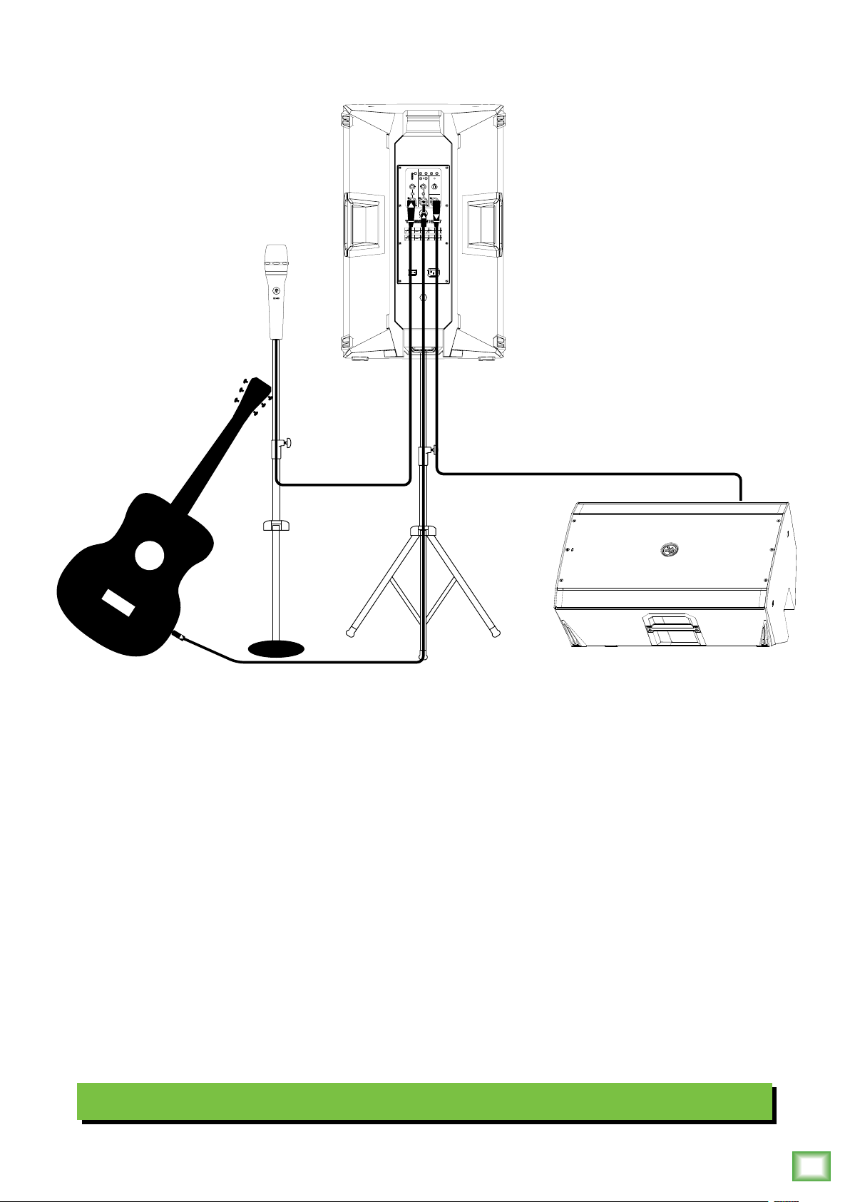
ThumpXT loudspeakers are the perfect tool for singer-songwriters touring the local coee shops. Bring your favorite axe
and mic, ThumpXT loudspeakers and cables and power cords.
In this example, a Mackie EM-89D microphone is connected to the channel input of a ThumpXT loudspeaker, used
as the main PA. The Channel gain knob should be set to Mic. The Mic/Line switch should be ENGAGED [Mic], as well.
Lastly, set the voicing mode to live.
Now grab your axe and plug it directly into the channel 2 input. Or if you use eects, connect the guitar to the eects
input and another cable from the eects output to the channel 2 input. Note that the gain knob is set to Line.
An additional ThumpXT loudspeaker will be used for monitoring purposes. Simply connect a cable from the ThumpXT
PA’s THRU jack to the ThumpXT monitor’s channel input. This gain knob should also be set to Line and the voicing mode set
to monitor.
Keep in mind that these “MIC” and “LINE” markings are for reference only and may need to be raised or lowered.
Singer-Songwriter Setup
Owner’s Manual
5
Page 6
Hookup Diagrams continued…
MUSIC
FEEDBACK
OUTDOOR
FRONT
VOICING MODES
DUCKING
ELIMINATOR
MODE
LED
MUSIC
LIVE
OVERLOADPAIR LINK
CLUB
MON
CH2 MAIN
CH1
GAIN VOLUME
GAIN
U U
U
LINE
LINE MIC
-
MAX
MAXMIN MIN
MAX
∞
LINE
MIC
THRU
VOICING MODES
LIVE
MUSIC
MON
CLUB
MUSIC
FEEDBACK
OUTDOOR
FRONT
VOICING MODES
DUCKING
ELIMINATOR
MODE
LED
MUSIC
LIVE
OVERLOADPAIR LINK
CLUB
MON
CH2 MAIN
CH1
GAIN VOLUME
GAIN
U U
U
LINE
LINE MIC
-
MAX
MAXMIN MIN
MAX
∞
LINE
MIC
THRU
VOICING MODES
LIVE
MUSIC
MON
CLUB
USB 3-4
MUTE
USB 1-2
MUTEMUTE MUTE
MUTE MUTE MUTE
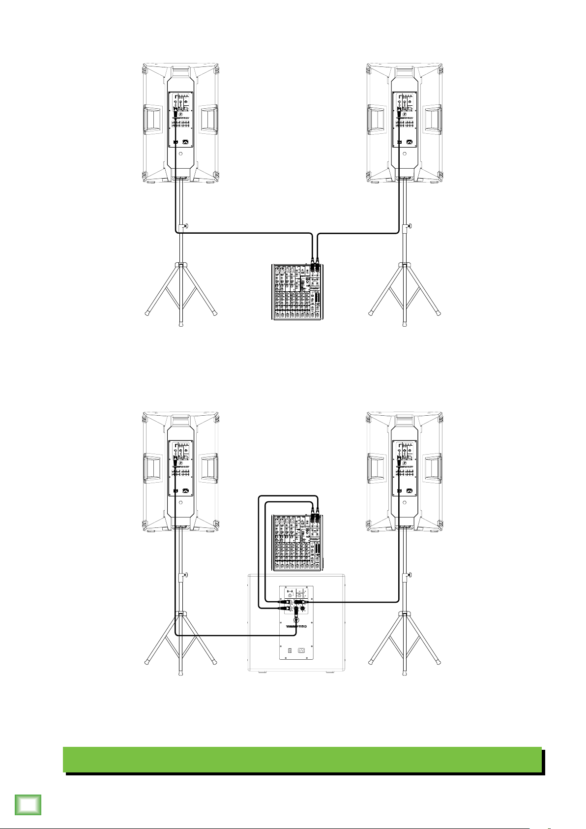
In this example, a ProFX0v3 mixer is connected directly to two Thump25XT loudspeakers. It is the perfect setup
for a small club or... a fun karaoke house party! Simply connect the L/R outputs of the ProFX0v3 mixer to the channel
input of each ThumpXT loudspeaker. Set the voicing mode of both to live or club. The gain knob on both should
be set to Line. The Mic/Line switches should be disengaged [Line], as well. Keep in mind that these “MIC” and “LINE”
markings are for reference only and may need to be raised or lowered.
MUSIC
FEEDBACK
MUSIC
FEEDBACK
OUTDOOR
FRONT
VOICING MODES
DUCKING
ELIMINATOR
MODE
LED
MUSIC
LIVE
OVERLOADPAIR LINK
CLUB
MON
CH2 MAIN
CH1
GAIN VOLUME
GAIN
U U
U
LINE
LINE MIC
-
MAX
MAXMIN MIN
MAX
∞
LINE
MIC
THRU
VOICING MODES
MUSIC
LIVE
MON
CLUB
USB 3-4
MUTE
USB 1-2
MUTEMUTE MUTE
MUTE MUTE MUTE
OUTDOOR
FRONT
VOICING MODES
DUCKING
ELIMINATOR
MODE
LED
MUSIC
LIVE
OVERLOADPAIR LINK
CLUB
MON
CH2 MAIN
CH1
GAIN VOLUME
GAIN
U U
U
LINE
LINE MIC
-
MAX
MAXMIN MIN
MAX
∞
LINE
MIC
THRU
VOICING MODES
MUSIC
LIVE
MON
CLUB
Thump212XT and Thump215XT 1400W Enhanced Powered Loudspeaker Series
6
HIGH PASS MODE
FRONT LED PHASE
FLAT
PUNCH
OFF
ON
DEEP
VARIABLE
NORMAL
INVERT
120Hz
U
SIG/OL
FR OUTPUT
STEREO
+6dB-6dB
160Hz80Hz
MONO
A
A
B B
INPUT HIGH PASS
FULL RANGE
OUT
OUT
If you desire a little more boom, add a Thump subwoofer to the mix. Here, the L/R outputs of a ProFX0v3 mixer
are connected directly to the A and B inputs of a Thump5S subwoofer. Then the High-Pass Outs of the subwoofer
are connected to the channel inputs of a pair of Thump25XT loudspeakers. Set the high pass mode of the sub to
your preferred choice and the voicing mode of both loudspeakers to live or club. The gain knob on both should be set
to Line. Keep in mind that these “MIC” and “LINE” markings are for reference only and may need to be raised or lowered.
Small Club System
Thump212XT and Thump215XT 1400W Enhanced Powered Loudspeaker Series
Page 7
Hookup Diagrams continued…
MUSIC
FEEDBACK
OUTDOOR
FRONT
VOICING MODES
DUCKING
ELIMINATOR
MODE
LED
MUSIC
LIVE
OVERLOADPAIR LINK
CLUB
MON
CH2 MAIN
CH1
GAIN VOLUME
GAIN
U U
U
LINE
LINE MIC
-
MAX
MAXMIN MIN
MAX
∞
LINE
MIC
THRU
Owner’s Manual
MUSIC
FEEDBACK
OUTDOOR
FRONT
VOICING MODES
DUCKING
ELIMINATOR
MODE
LED
MUSIC
LIVE
OVERLOADPAIR LINK
CLUB
MON
CH2 MAIN
CH1
GAIN VOLUME
GAIN
U U
U
LINE
LINE MIC
-
MAX
MAXMIN MIN
MAX
∞
LINE
MIC
THRU
VOICING MODES
LIVE
MUSIC
MON
CLUB
HIGH PASS MODE
FLAT
PUNCH
DEEP
VARIABLE
120Hz
SIG/OL
160Hz80Hz
A
B B
INPUT HIGH PASS
OUT
FRONT LED PHASE
U
VOICING MODES
LIVE
MUSIC
MON
CLUB
HIGH PASS MODE
FRONT LED PHASE
FLAT
OFF
ON
NORMAL
INVERT
FR OUTPUT
STEREO
+6dB-6dB
MONO
A
FULL RANGE
OUT
PUNCH
DEEP
VARIABLE
120Hz
U
SIG/OL
160Hz80Hz
A
B B
INPUT HIGH PASS
OUT
OFF
ON
NORMAL
INVERT
FR OUTPUT
STEREO
+6dB-6dB
MONO
A
FULL RANGE
OUT
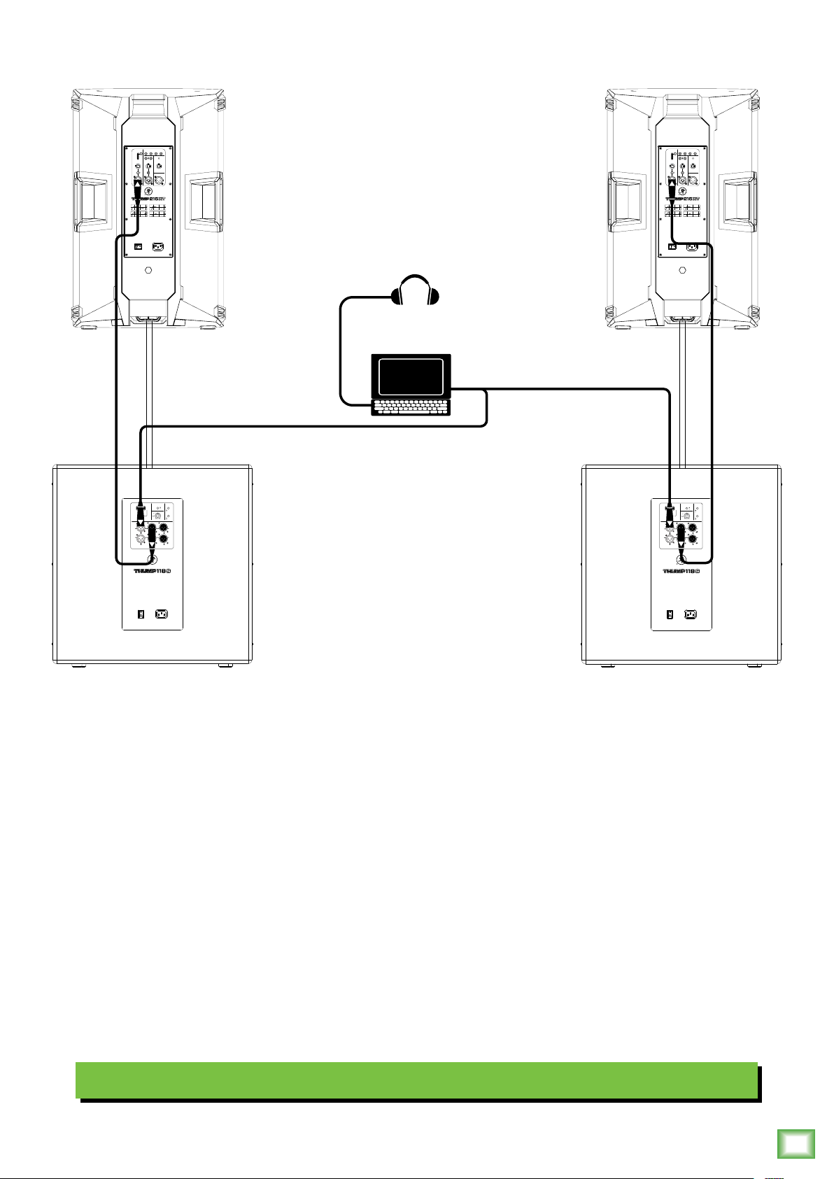
Perhaps you’re a DJ playing bumpin’ tunes in the middle of the night to a crowd that’s groovin’
and dancin’ to your fine selection.
In this example, a laptop is connected to the inputs of two Thump8S subwoofers.
The High-Pass Out of each subwoofer is then connected to the input of each Thump25XT loudspeaker.
Additionally, a set of Mackie MC-450 headphones is connected to the phones jack of the laptop.
The gain knob on both loudspeakers should be set to Line. The Mic/Line switches should be disengaged [Line], as well.
Additionally, set the high pass mode of the sub to your preferred choice and the voicing mode of both loudspeakers to live
or club. Keep in mind that these “MIC” and “LINE” markings are for reference only and may need to be raised or lowered.
DJ System
Owner’s Manual
7
Page 8
Hookup Diagrams continued…
To next
ThumpXT
loudspeaker
input
CH1 CH2 MAIN
U
LINE MIC
MAX
∞
LINE
MIC
LINE
-
∞
GAIN VOLUMEGAIN
U U
MAX
To next
ThumpXT
Main
Outs
CH1 CH2 MAIN
GAIN VOLUMEGAIN
U U
U
LINE MIC
LINE
-
-
-
MAX
∞
THRU
MAX
∞
LINE
MIC
MAX
MAX
∞
∞
THRU
MUTE
MUTEMUTE MUTE
USB 3-4
USB 1-2
MUTE MUTE MUTE
CH1 CH2 MAIN
GAIN VOLUMEGAIN
U U
U
LINE MIC
LINE
-
MAX
MAX
∞
∞
LINE
MIC
-
MAX
∞
THRU
ProFX10v3 Mixer
loudspeaker
input
CH1 CH2 MAIN
GAIN VOLUMEGAIN
U U
U
LINE MIC
LINE
-
MAX
MAX
∞
∞
LINE
MIC
-
MAX
∞
THRU
To next
ThumpXT
loudspeaker
input
CH1 CH2 MAIN
GAIN VOLUMEGAIN
U U
U
LINE MIC
LINE
-
-
MAX
∞
LINE
MIC
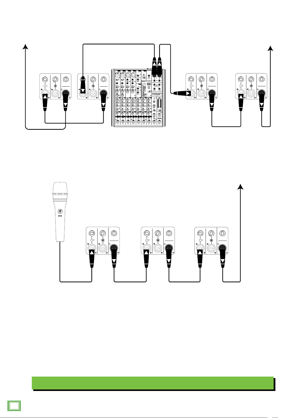
ThumpXT loudspeakers may be daisy-chained via the “THRU” jack which outputs all inputs. Simply plug the signal source
Thump212XT and Thump215XT 1400W Enhanced Powered Loudspeaker Series
MAX
MAX
∞
∞
THRU
CH1 CH2 MAIN
GAIN VOLUMEGAIN
U U
U
LINE MIC
LINE
-
MAX
MAX
∞
∞
LINE
MIC
CH1 CH2 MAIN
GAIN VOLUMEGAIN
U U
U
LINE MIC
-
MAX
∞
THRU
LINE
-
-
MAX
∞
LINE
MIC
MAX
MAX
∞
∞
THRU
(i.e., mixer output or microphone) into the input jack(s), and patch that loudspeaker’s mix out jack to the next loudspeaker’s
input jack, and so on, daisy-chaining multiple ThumpXT loudspeakers. See above for visual representations of daisy-chaining.
NOTE: Make sure to set the gain knob(s) correctly. In the top diagram, all input channes are set to “LINE” and in the bottom
diagram, input channel of the first ThumpXT is set to “MIC”, but the remaining ones should be set to “LINE”. Keep in mind
that these “MIC” and “LINE” markings are for reference only and may need to be raised or lowered.
Daisy-Chaining Multiple ThumpXT Loudspeakers
8
Thump212XT and Thump215XT 1400W Enhanced Powered Loudspeaker Series
Page 9
Hookup Diagrams continued…
MUSIC
FEEDBACK
OUTDOOR
FRONT
VOICING MODES
DUCKING
ELIMINATOR
MODE
LED
MUSIC
LIVE
OVERLOADPAIR LINK
CLUB
MON
CH2 MAIN
CH1
GAIN VOLUME
GAIN
U U
U
LINE
LINE MIC
-
MAX
MAXMIN MIN
MAX
∞
LINE
MIC
THRU
VOICING MODES
MUSIC
LIVE
MON
CLUB
Owner’s Manual
MUSIC
FEEDBACK
OUTDOOR
FRONT
VOICING MODES
DUCKING
ELIMINATOR
MODE
LED
MUSIC
LIVE
OVERLOADPAIR LINK
CLUB
MON
CH2 MAIN
CH1
GAIN VOLUME
GAIN
U U
U
LINE
LINE MIC
-
MAX
MAXMIN MIN
MAX
∞
LINE
MIC
THRU
VOICING MODES
MUSIC
LIVE
MON
CLUB
HIGH PASS MODE
FRONT LED PHASE
FLAT
PUNCH
OFF
ON
DEEP
VARIABLE
NORMAL
INVERT
120Hz
U
FR OUTPUT
SIG/OL
STEREO
+6dB-6dB
160Hz80Hz
MONO
A
A
B
B
INPUT HIGH PASS
FULL RANGE
OUT
OUT
HIGH PASS MODE
FRONT LED PHASE
FLAT
PUNCH
OFF
ON
DEEP
VARIABLE
NORMAL
INVERT
120Hz
U
FR OUTPUT
SIG/OL
STEREO
+6dB-6dB
160Hz80Hz
MONO
A
A
B
B
INPUT HIGH PASS
FULL RANGE
OUT
OUT
HIGH PASS MODE
FRONT LED PHASE
FLAT
PUNCH
OFF
ON
DEEP
VARIABLE
NORMAL
INVERT
120Hz
U
FR OUTPUT
SIG/OL
STEREO
+6dB-6dB
160Hz80Hz
MONO
A
A
B
B
INPUT HIGH PASS
FULL RANGE
OUT
OUT
HIGH PASS MODE
FLAT
DEEP
A
B
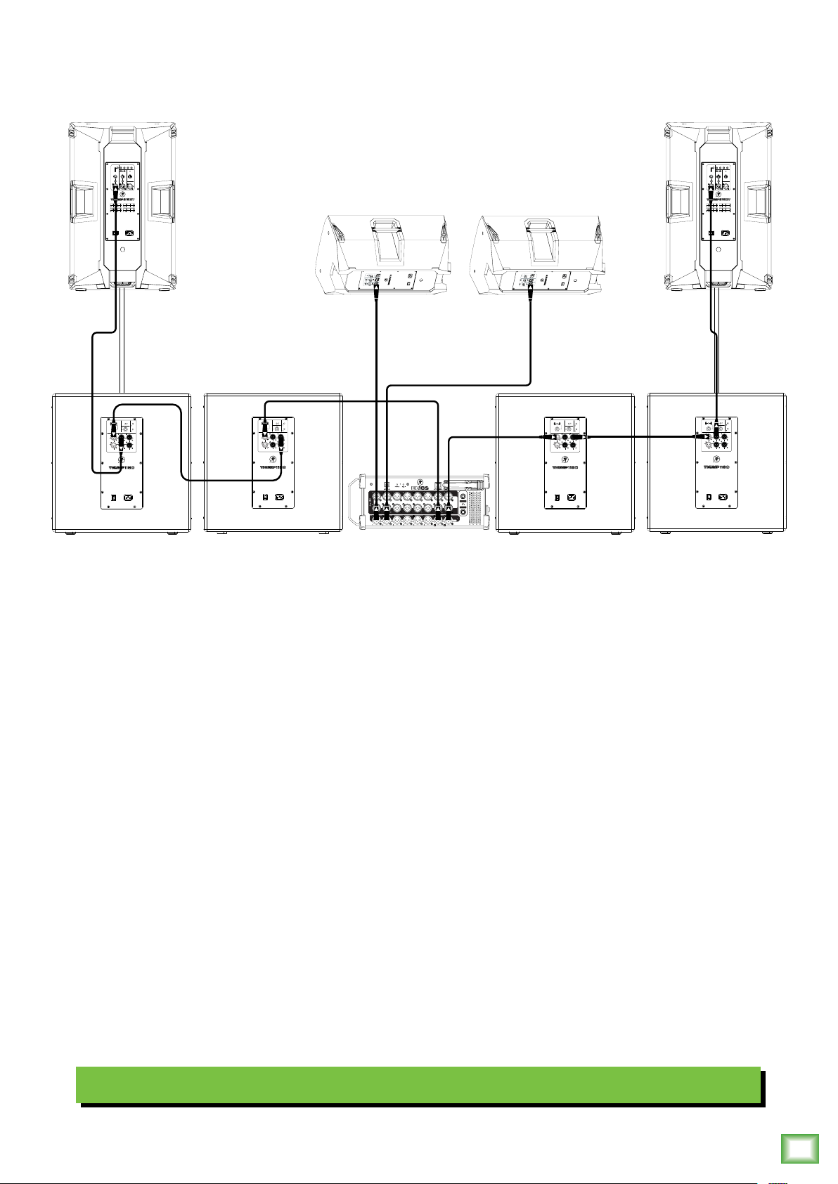
Here’s how to set up a large club system. In this example, the L/R outputs of a DL6S mixer are connected directly
to the channel A inputs of a pair of Thump8S subwoofers. The Full Range Out of each subwoofer is then connected
to the inputs of an additional pair of Thump8S subwoofers.
From here, the High Pass Out of the two outer Thump8S subwoofers are connected directly to the inputs
of a set of Thump25XT loudspeakers. Then set the subwoofer’s High Pass Mode to Deep and the voicing
mode of both loudspeakers to live or club. Talk about beefy low end!
FRONT LED PHASE
PUNCH
OFF
ON
VARIABLE
NORMAL
INVERT
120Hz
U
FR OUTPUT
SIG/OL
STEREO
+6dB-6dB
160Hz80Hz
MONO
A
B
INPUT HIGH PASS
FULL RANGE
OUT
OUT
Outputs and 2 from the mixer may be used as aux sends; these are connected directly to the channel inputs of a pair
of Thump25 loudspeakers to be used as monitors for the band. The gain knob on all Thump loudspeakers in this example
should be set to Line. Lastly, all Mic/Line switches should be disengaged [Line]. Keep in mind that these “MIC” and “LINE”
markings are for reference only and may need to be raised or lowered.
Large Club System
Owner’s Manual
9
Page 10
ThumpXT Series Loudspeakers: Rear Panel Features
2
SHIELD
TIPSLEEVE
RING
SLEEVERING
TIPSLEEVE
SLEEVE
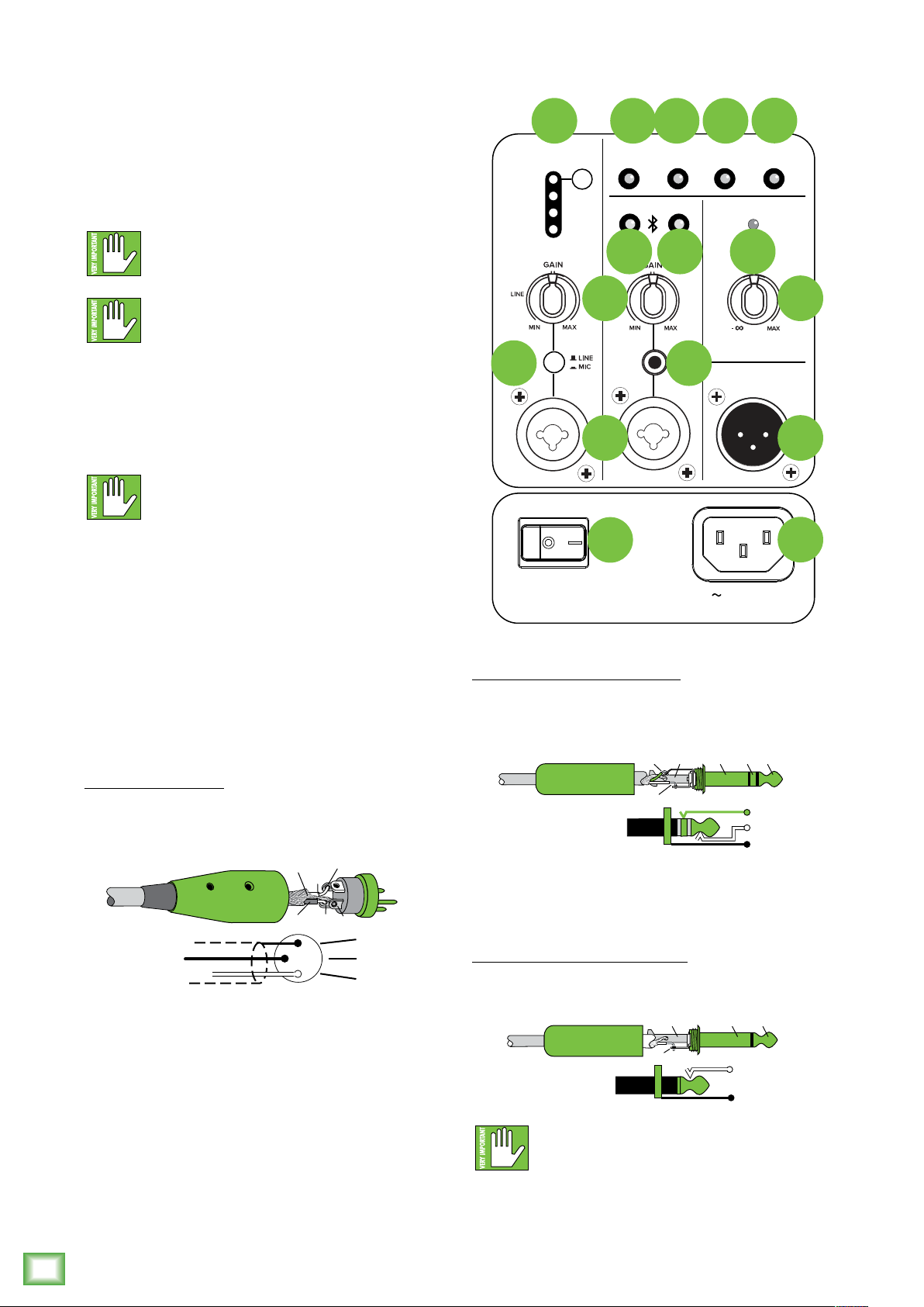
. Power Connection
This is a standard 3-prong IEC power connector.
Connect the detachable power cord (included in
the packaging with the loudspeaker) to the power
receptacle, and plug the other end of the power
cord into an AC outlet.
Make sure that the AC power is matched to
the AC power indicated on the rear panel
(near the IEC receptacle).
9 0 2
VOICING MODES
MUSIC
LIVE
CLUB
MON
CH1
OUTDOOR
MODE
CH2 MAIN
20
MUSIC
DUCKING
2
FEEDBACK
ELIMINATOR
OVERLOADPAIR LINK
VOLUME
6
3
FRONT
LED
Disconnecting the plug’s ground pin is
dangerous. Don’t do it!
2. Power Switch
Press the right side of this rocker switch inwards
to turn on the loudspeaker. Press the lef side of this
rocker switch inwards to turn o the loudspeaker.
As a general guide, the mixer (or other
signal source) should be turned on first,
subwoofers next, and loudspeakers last.
As such, the loudspeakers should also be turned
o first, followed by the subwoofers, then the mixer.
This will reduce the possibility of any turn-on or
turn-o thumps and other noises generated by any
upstream equipment from coming out of the speakers.
3. XLR and /4" Combo Input Jacks
Input channels and 2 may accept a balanced
mic signal using an XLR connector. They are wired
as follows, according to standards specified by
the AES (Audio Engineering Society).
6
5
3
2
/4" TRS Balanced Mono Wiring:
Sleeve = Shield
Tip = Hot (+)
Ring = Cold (–)
4
THRU
100-240VAC
50-60 Hz 75W
8
7
XLR Balanced Wiring:
Pin = Shield (ground)
Pin 2 = Positive (+ or hot)
Pin 3 = Negative (– or cold)
HOT
3
1
1
2
Thump212XT and Thump215XT 1400W Enhanced Powered Loudspeaker Series
COLD
3
In addition to accepting a balanced mic signal
using an XLR connector, these input channels may
also accept /4" line-level signals driven by balanced
or unbalanced sources.
To connect balanced lines to these inputs, use
a /4" Tip-Ring-Sleeve (TRS) plug. “TRS” stands
for Tip-Ring-Sleeve, the three connection points
available on a stereo /4" or balanced phone jack
or plug. TRS jacks and plugs are used for balanced
signals and are wired as follows:
SHIELD
COLD
HOT
TIP
RING
TIP
SLEEVE
To connect unbalanced lines to these inputs,
use a /4" mono (TS) phone plug, wired as follows:
/4" TS Unbalanced Mono Wiring:
Sleeve = Shield
Tip = Hot (+)
TIP
TIP
SLEEVE
NEVER connect the output of an amplifier
directly to a ThumpXT input jack. This could
damage the input circuitry!
10
Thump212XT and Thump215XT 1400W Enhanced Powered Loudspeaker Series
Page 11
ThumpXT Series Loudspeakers: Rear Panel Features continued...
1
SHIELD
Owner’s Manual
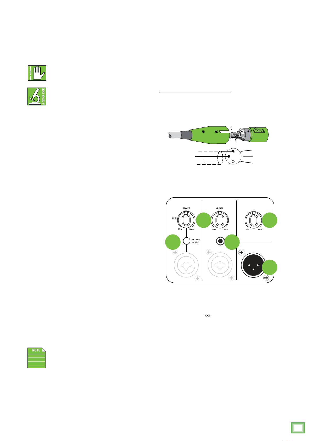
4. /8" Input Jack [Ch. 2]
This input channel may accept an /8" line-level
signal from a phone, tablet, MP3 player, or other signal
source.
NEVER connect the output of an amplifier
directly to a ThumpXT input jack. This could
damage the input circuitry.
The /8" line-level connection may be used
simultaneously with channel 2’s combo
jack – XLR or /4" – and/or Bluetooth
connection. In other words, if there is a physical
connection to the /8" line input, another physical
connection to the combo jack AND a device is
connected via Bluetooth, none of those inputs
will be interrupted. An easy way to look at it is...
there are extra inputs! The /8" line-level connection
and XLR (or /4") connection sum together
and do not override each other.
5. Mic / Line Switch [Ch. ]
Because an XLR connector may be connected
to a mic or an instrument, this switch adjusts
the channel’s input sensitivity to optimize channel
for mic or line-level signals. If a mic is connected,
this switch should be engaged and the gain knob –
more below – set to mic. If an instrument is connected
to channel (via XLR), this switch should be
disengaged and the gain knob set to line.
7. Thru Jack
This is a male XLR-type connector that produces
the mix from the input jacks. Use it to daisy-chain
several ThumpXT loudspeakers together o the same
signal source(s).
They are wired as follows, according to standards
specified by the AES (Audio Engineering Society):
Balanced XLR Output Connector
Pin – Shield (ground)
Pin 2 – Positive (+ or hot)
Pin 3 – Negative (– or cold)
3
COLD
2
HOT
1
3
2
SHIELD
COLD
HOT
See page 8 to learn more about daisy-chaining
ThumpXT loudspeakers.
CH1
CH2 MAIN
VOLUME
86
6. Gain Knobs [Ch. and 2]
If you haven’t already, please read the “Quick Start”
section on page 4. Setting the gain correctly will ensure
that the preamplifier’s gain is not too high, where
distortion could occur, and not too low, where
the quieter, exquisitely-delicate passages might
be lost in background noise.
The gain knobs allow signals from the outside world
to be adjusted to run through each channel at optimal
internal operating levels.
If connecting mixer outputs to ThumpXT inputs,
set the gain knobs to 9:00 [“LINE”] for optimal
sound and performance.
Keep in mind that these “MIC” and “LINE”
markings are for reference only and may
need to be raised or lower.
45
THRU
7
8. Main Volume Knob
The volume knob adjusts the overall signal level
at the input to the built-in power amplifiers.
It ranges from O (– ) to MAX (maximum gain).
• Thump loudspeakers are designed to operate
with a +0 dBu signal when all knobs are at
the center position.
• Thump loudspeakers may accept up to a +20 dBu
signal by turning down the channel gain in line mode.
• Turning the main knob past center position will
provide enough gain to connect a microphone directly.
Most microphones will want the knob somewhere
around the 9:00 position. For safety, if you’re plugging
in a mic, start with the volume o and gradually
rotate it clockwise until you achieve the desired
volume... and be on the lookout for the dreaded
shriek of the feedback monster.
Owner’s Manual
11
Page 12
OVERLOAD
PAIR
LINK
ThumpXT Series Loudspeakers: Rear Panel Features continued...
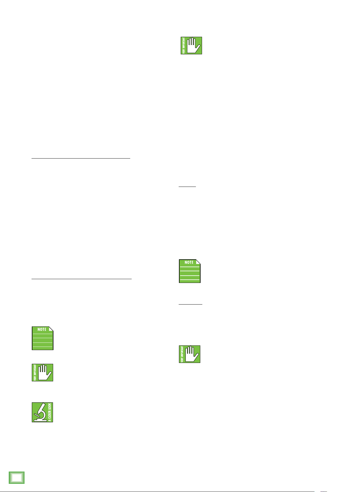
9. Voicing Modes
The voicing mode allows you to change the
ThumpXT’s voicing to tailor it to best suit your
particular application. Press the voicing mode
button repeatedly until the LED of the voicing
mode you desire is illuminated.
The four voicing modes are as follows:
• MUSIC Voicing Mode – This plug-and-play
mode is perfect for listening to mastered music
and is optimized to maintain tonal balance
at peak output volume.
• LIVE Voicing Mode – This mode works well
for singer-songwriters, as it features an upper bass
parametric scoop to reduce unwanted low frequency
color and adds boost to upper mid-range and high
frequencies.
• CLUB Voicing Mode – This mode is full range,
but focuses on increased bass and brilliant high
frequencies. This is the place to start for most
DJ / music playback applications.
• MONITOR Voicing Mode – Monitor mode
was tailored to reduce excess low frequency output
when coupled with the ground, while also reducing
mid-range bite for the artist(s).
This mode should only be engaged when
the speaker is in its monitor orientation
on a stage or floor... if not, the low-end
will sound very lean.
9 0 2
VOICING MODES
MUSIC
LIVE
CLUB
MON
OUTDOOR
MODE
MUSIC
DUCKING
FEEDBACK
ELIMINATOR
3
FRONT
LED
. Music Ducking
Have you been to an event where music was playing,
then when someone spoke into the mic, that the music
volume decreased greatly (but was still there)? That’s
called “music ducking”!
When the music ducking switch is engaged,
the channel 2 level will decrease when a mic signal
is present on channel . Additionally, the LED will
illuminate green. As if by magic, once the speaking is
completed, the music will return back to its previous
level. True wizards, those engineers... and none of them
have long grey beards, robes and pointy hats.
The audio nerds out there might like
to know that the channel 2 level decreases
by 0 dBu when a mic signal is present
in channel (and when auto-ducking
is engaged, of course).
2. Feedback Eliminator
The multi-band feedback eliminator hunts
down oending feedback frequencies and applies
up to six notch filters automatically to destroy
feedback and maximize gain prior to feedback.
This is a great tool for when an engineer is not present.
• O [Default] – The feedback eliminator is not
engaged. If filters have been applied, this setting will
retain its current filter settings if there are any, but they
will not be engaged until it is turned back on.
• On – When the automatic feedback eliminator is
turned on, scanning occurs continuously. The six filters
will engage sequentially when feedback is present until
all are used and then it will be locked. If feedback is
identified on an existing filter, the notch will deepen in
three steps to further destroy the oending feedback
frequency. Pretty cool, huh?! The LED will illuminate
green when engaged.
The feedback eliminator ONLY aects
channel (mic and line mode).
Thump212XT and Thump215XT 1400W Enhanced Powered Loudspeaker Series
12
0. Outdoor Mode
Regarding outdoor mode... in a sentence, choose
whether you are using ThumpXT inside or outside.
The speaker’s voicing is altered to the environment.
That’s all you need to know, but we’re going to give
you more!
When speakers are outside, a combination of low
and high frequencies don’t build up the way they
do inside. ThumpXT corrects for that by boosting
the frequency ranges that become deficient
so the speaker sounds the same outside as when
it’s inside. You make the selection, we’ll do the rest!
The outdoor mode LED will illuminate green
when engaged (outdoors).
Thump212XT and Thump215XT 1400W Enhanced Powered Loudspeaker Series
3. Front LED
There is a single horizontal LED located near
the bottom-front of each ThumpXT. This LED
illuminates green when the front LED switch
is engaged. Additionally, the switch’s LED will
illuminate green. Disengage the switch if you
do not want the front panel LED to illuminate.
We like to call this ‘stealth’ mode.
When two ThumpXT loudspeakers
are linked together in stereo mode,
the feedback eliminator should only
be engaged on the primary ThumpXT.
Page 13
ThumpXT Series Loudspeakers: Rear Panel Features continued...
Owner’s Manual
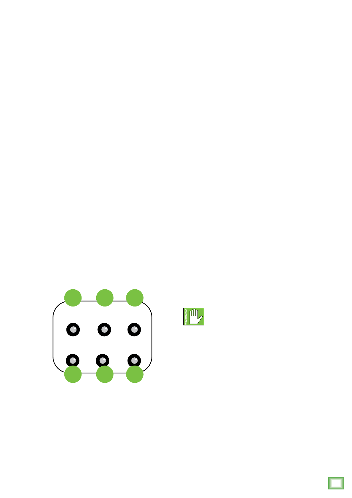
4. Fan On / O
One of our favorite things about the Thump Series
is the Summer cool-o / Winter warm-up feature.
Is it hotter than the blazes out where you are?
We’ve got you covered!
Simply press this switch to turn the fan on and o.
The speaker begins acting like a fan, blowing out cool
air!
The LED will illuminate green when engaged (fan on).
5. Fan Speed
Want more? Of course you do! Here you’re able to
select the speed setting of the fan from (the lowest
setting) to 5 (the highest setting).
Quickly press this button to what setting you
would like, up to five times. The LED will flash green
the number of the current setting.
7. Heat On / O
The fan feature is nice... but what if it’s 40˚ below with
20 feet of snow outside and a wind chill factor of the
frozen tundra? Yeah, we’ve got you covered there, too!
The built-in heater is great, especially when in the
monitor position. Gotta love warm tootsies! Just like
with the fan, simply press this switch to turn the heat
on and o. The LED will illuminate green when engaged
(heat on).
8. Heat Level
If the temperature is the aforementioned “frigid”,
we’re pretty confident that you’re going to want
to crank the heat... perhaps not, but we’d bet on it!
This works similarly to that of the fan speed
with settings ranging from (low heat) to 5
(cranked heat). Quickly press this button to what
setting you would like, up to five times. The LED
will flash green the number of the current setting.
6. Mist Level
A rotating fan with multiple speeds is a nice feature,
but when a mister is thrown in...? Oh, all bets are o!
When the mist level switch is engaged, a light spray
of water is dispersed to keep the band and crowd nice
and refreshed throughout the performance. The LED
will illuminate green when engaged (mist on).
4
FAN
ON / OFF
HEAT
ON / OFF
7
5
FAN
SPEED
HEAT
LEVEL
8
6
MIST
LEVEL
ROTATE
9
9. Rotate
Last, but absolutely not least... the fan AND heater are
both rotatable (although the one switch controls whichever one is engaged, of course).
The rotation speed may be set to (low), 2 (medium),
or 3 (high). As with the fan speed and heat level,
quickly press this button to what setting you would
like, up to three times. The LED will flash green
the number of the current setting.
Please note that the rotation function only
works when the loudspeaker is mounted
on the T100 tripod or SPM400 pole mount.
Operators are standing by!
Owner’s Manual
13
Page 14
ThumpXT Series Loudspeakers: Rear Panel Features continued...
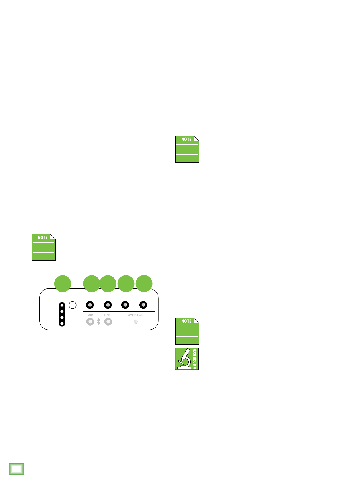
20. Bluetooth / Pair
While not a “physical” connection, stereo channel 3/4
is considered the Bluetooth channel and its volume
is raised and lowered via the device.
This is how to connect your device to the ThumpXT
via Bluetooth! Read on...
Upon powering up the ThumpXT, the Bluetooth
function is either:
() In sleep mode. See ‘Pairing and connecting
for the first time’ (to the right) or...
(2) ...Paired and connected. See ‘Previously paired
and connected devices’ (also to the right).
Pairing and connecting for the first time:
To enter pairing mode, press and hold the pair switch
down for at least three seconds. The LED will illuminate
and slow flash blue for approximately 30 seconds while
in pairing mode. [The LED will continue to flash until it
has successfully paired and connected].
While ThumpXT is in pairing mode, simultaneously
scan for Bluetooth devices on your device. You should
see ThumpXT appear in the list of “available devices”.
Select it by tapping it. From there, your Bluetooth
device should indicate that it is successfully
connected. Additionally, the pair button will stop
flashing and remain solid blue. If it does not, start
the pairing process again, and make sure that
ThumpXT and your device are both in pairing
mode at the same time.
Previously paired and connected devices:
The Bluetooth connection will disconnect if it’s out
of range or if ThumpXT is powered o. Previously paired
and connected devices will automatically reconnect
(unless turned o via the Thump Connect 2 App)
and the pair button will once again illuminate
a brilliant blue.
To drop the device from being paired with
the ThumpXT, press and hold the ‘Bluetooth
Pair’ button down for at least three seconds.
Thump212XT and Thump215XT 1400W Enhanced Powered Loudspeaker Series
If this occurs, manually reconnect the Bluetooth
connection.
connection. In other words, if there is a physical
connection to the /8" line input, another physical
connection to the combo jack AND a device
is connected via Bluetooth, none of those inputs
will be interrupted. An easy way to look at it is...
there are extra inputs!
The Bluetooth connection may disconnect
when aected by electrostatic discharge
(ESD) or electrical fast transients (EFT).
As mentioned earlier, a Bluetooth connection
may be used simultaneously with the combo
jacks – XLR or /4" – and/or /8" line-level
If a phone – or two dierent phones –
have been paired via Bluetooth with two
ThumpXT loudspeakers, they will not link.
The options are either () one phone connected via
Bluetooth and ThumpXT loudspeakers may
be linked or (2) two phones connected via Bluetooth
to two dierent ThumpXT loudspeakers and they
may be not be linked.
2. Speaker Link
Two ThumpXT loudspeakers may either be linked together or separate (i.e. not linked). Additionally, there
are options when linked, as they support stereo and
zone (dual mono) linking. However, those features are
only available when connected to the Thump Connect 2
App. It will default to stereo with just the hardware.
To link:
In order to link two ThumpXT loudspeakers,
press and hold the ‘Link’ switch down on the primary
ThumpXT loudspeaker until the blue LED begins
slow-flashing.
Within (approximately) 30 seconds, a quick press
and release of the ‘Link’ button on the secondary
ThumpXT allows both units to “see” each other,
handshake and link. The LEDs on both units will stop
flashing and remain solid, indicating great success!.
The ThumpXT loudspeakers will continue
to auto-link on every power-up unless this
feature is turned o via the Thump Connect
2 App.
To unlink:
In order to unlink the two ThumXT loudspeakers,
press and hold the ‘Link’ momentary switch / LED down
on one of the ThumpXT loudspeakers until the blue
LED turns o. The other ThumpXT will automatically
unlink and the LEDs on both units will turn o.
If a phone – or two dierent phones – have
been paired via Bluetooth with two
ThumpXT loudspeakers, they will not link.
The options are either () one phone connected
via Bluetooth and ThumpXT loudspeakers may
be linked or (2) two phones connected via Bluetooth
to two dierent ThumpXT loudspeakers and they
may be not be linked.
14
Thump212XT and Thump215XT 1400W Enhanced Powered Loudspeaker Series
Page 15
22. Overload LED
The ThumpXT has a built-in limiter that helps
to prevent the amplifier outputs from clipping
or overdriving the transducers. The limit indicator
illuminates red when the limiter is activated.
It’s okay for it to blink occasionally, but if it blinks
frequently or lights continuously, turn down
the gain knob(s) until it only blinks occasionally.
Excessive limiting may lead to overheating,
which in turn trips the thermal protect
circuitry and interrupts the performance.
See ‘Thermal Protection’ on page 6 for more
information.
Owner’s Manual
Final Thoughts
Just a few final thoughts before we dive into a little
more boring “techy”-type stu. For starters, we would
like to remind you once again that ThumpXT works
great on its own, but when paired and connected
with a device using the Thump Connect 2 app, your
world of possibilities really opens up!
Factory Reset
Let’s also talk factory resets. Since settings may
be changed via Thump Connect 2, it may be necessary
to reset the ThumpXT to its factory settings.
There are two kinds of resets:
• Sof Reset – Just a simple power cycle will reset
all settings that were previously set via the rear
panel and/or app back to their default settings
(except for Bluetooth and linked speakers that
are stored within ThumpXT).
• Hard Reset – A hard reset resets the entire
unit to its factory default, including auto-connect
and auto-link. A hard reset may be accomplished
by pressing and holding down the ‘Voicing Modes’
and ‘Outdoor Mode’ buttons simultaneously
for approximately five seconds on boot up.
Release the buttons when multiple voicing
mode LEDs light up simultaneously, as this
indicates success.
Please keep in mind that this erases all
settings, including any levels, EQs, etc. that
may have been set. Be sure to power down
any amps and/or powered speakers before
resetting ThumpXT.
If you use the factory default key
combination, you are also wiping the
ThumpXT’s memory of previously paired
devices. To remedy this, on your phone,
tablet or other Bluetooth device, you will need to ‘forget
device’ in the Bluetooth settings, then re-pair in
order to regain communication and functionality.
Owner’s Manual
15
Page 16

Protection Circuitry
AC Power
ThumpXT loudspeakers employ a built-in limiter for
less distortion at peak levels. A dynamic bass response
circuit provides optimal low frequency response
regardless of overall output level. Additional protection
includes automatic thermal shutdown should the amp
overheat. However, with Class-D amp technology, which
is highly-ecient, this should never be a problem.
The protection circuits are designed to
protect the loudspeakers under reasonable
and sensible conditions. Should you choose
to ignore the warning signs [e.g. excessive distortion],
you can still damage the woofer in the loudspeaker
by overdriving it past the point of amplifier clipping.
Such damage is beyond the scope of the warranty.
Limiting
The polymer high frequency driver has its own
compression circuit which helps protect it from
damaging transient peaks. The compressor is
designed to be transparent and is not noticeable
under normal operating conditions.
Be sure the ThumpXT loudspeaker is plugged into
an outlet that is able to supply the correct voltage
specified for your model. It will continue to operate
at lower voltages, but will not reach full power.
Be sure the electrical service can supply enough
amperage for all the components connected to it.
We recommend that a sti (robust) supply
of AC power be used because the amplifiers place
high current demands on the AC line. The more power
that is available on the line, the louder the speakers
will play and the more peak output power will be
available for a cleaner, punchier bass. A suspected
problem
of “poor bass performance” is ofen caused by a weak
AC supply to the amplifiers.
Never remove the ground pin on the
power cord or any other component of the
ThumpXT
loudspeaker. This is very dangerous.
Overexcursion Protection
A subsonic filter circuit just prior to the power
amplifier prevents ultra-low frequencies from being
amplified. Excessive low-frequency energy can damage
the woofer by causing it to “bottom out,” also know
as overexcursion, which is equivalent to a mechanical
form of clipping.
Thermal Protection
All amplifiers produce heat. ThumpXT loudspeakers
are designed to be ecient both electrically
and thermally. In the unlikely event of the amplifier overheating, a built-in thermal switch will activate,
muting the signal.
Thump212XT and Thump215XT 1400W Enhanced Powered Loudspeaker Series
When the amplifier has cooled down to a safe
operating temperature, the thermal switch resets
itself, and the ThumpXT loudspeaker resumes normal
operation.
Care and Maintenance
Your ThumpXT loudspeakers will provide many years
of reliable service if you follow these guidelines:
• Avoid exposing the loudspeakers to moisture.
If they are set up outdoors, be sure they are under
cover if rain is expected.
• Avoid exposure to extreme cold (below freezing
temperatures). If you must operate the loudspeakers
in a cold environment, warm up the voice coils slowly
by sending a low-level signal through them for about
5 minutes prior to high-power operation.
• Use a dry cloth to clean the cabinets.
Only do this when the power is turned o.
Avoid getting moisture into any of the openings of
the cabinet, particularly where the drivers are located.
16
If the thermal switch activates, try turning down
the level control a notch or two on the mixing console
to avoid overheating the amplifier. Be aware that direct
sunlight and/or hot stage lights may be the culprit
of an amplifier overheating.
Thump212XT and Thump215XT 1400W Enhanced Powered Loudspeaker Series
Page 17
Placement
WARNING: Installation should only
be done by an experienced technician.
Improper installation may result in damage
to the equipment, injury or death. Make sure that
the loudspeaker is installed in a stable and secure
way in order to avoid any conditions that may be
dangerous for persons or structures.
ThumpXT loudspeakers are designed to sit on the
floor or stage as the main PA or as monitors. They may
also be pole-mounted via the built-in socket on
the bottom of the cabinet. Be sure the pole is capable
of supporting the weight of the loudspeaker.
The T00 is a great tripod option and the SPM400
is a nice choice when using a subwoofer.
These loudspeakers may also be flown via their
integrated fly points as detailed on the following
page. Be sure to read the PA-A2 Eyebolt Installation
Instructions, as well.
NEVER attempt to suspend a Thump
loudspeaker by its handles.
Check to make sure that the support surface
(e.g. floor, etc.) has the necessary mechanical
characteristics to support the weight of the
loudspeaker(s).
When pole-mounting loudspeakers, be sure that they
are stabilized and secured from falling over or being
accidentally pushed over. Failure to follow these
precautions may result in damage to the equipment,
personal injury, or death.
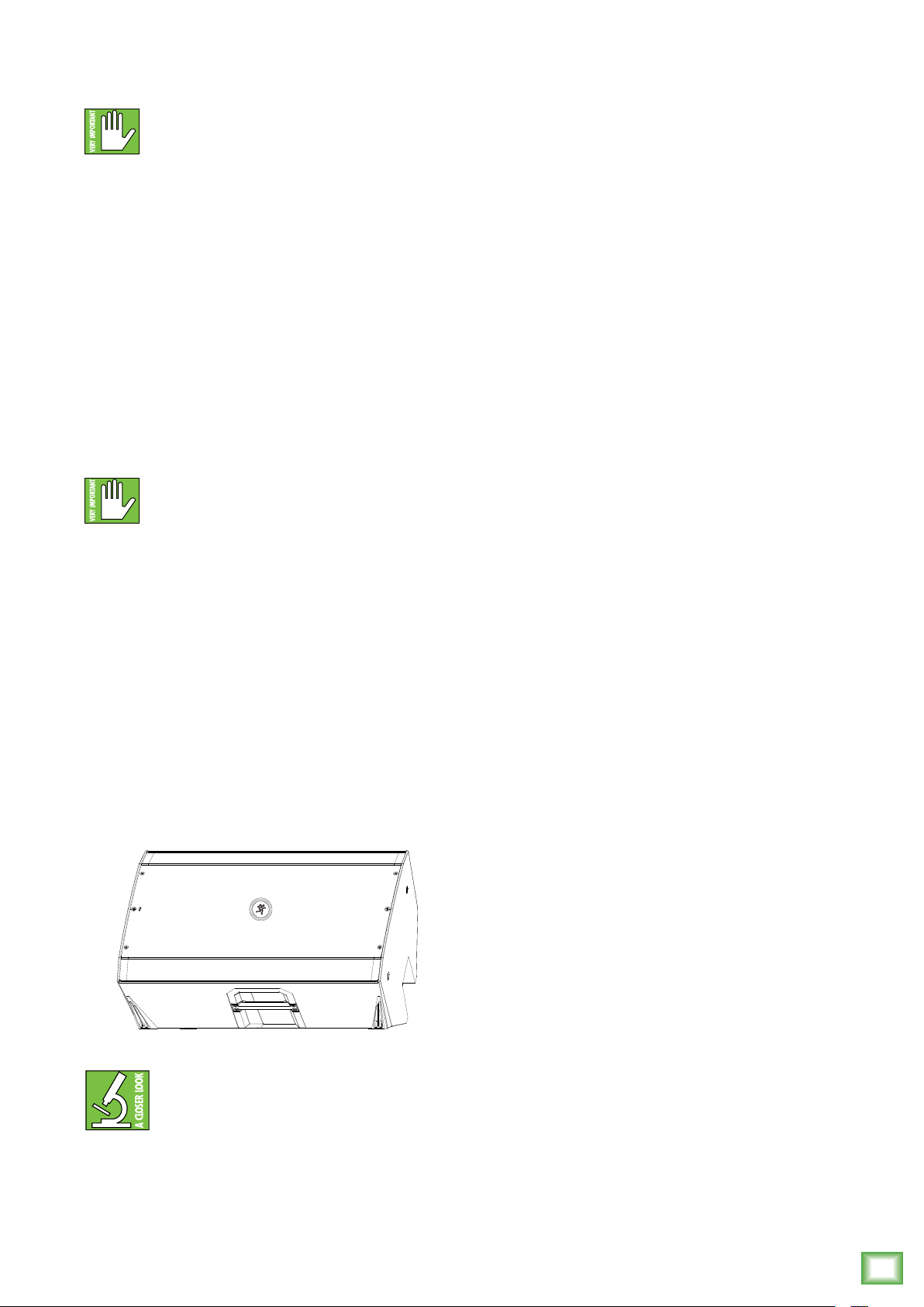
Thump loudspeakers may be laid out horizontally
as monitors for the band at a 40˚ angle (as seen below).
It is intended to be used only when the speaker
is in its wedge configuration and works best
when on a hard work surface, like a stage.
But, room acoustics play a crucial role
Owner’s Manual
in the overall performance of a sound system.
However, the wide high-frequency dispersion
of the ThumpXT loudspeakers helps to minimize
the problems that typically arise.
Here are some additional placement tips to help
overcome some typical room problems that might arise:
• Placing loudspeakers in the corners of a room
increases the low frequency output and can cause
the sound to be muddy and indistinct.
• Placing loudspeakers against a wall increases
the low frequency output, though not as much
as corner placement. However, this is a good way
to reinforce the low frequencies, if so desired.
• Avoid placing the speakers directly on a hollow
stage floor. A hollow stage can resonate at certain
frequencies, causing peaks and dips in the frequency
response of the room. It is better to place them
on a sturdy stand designed to handle the weight
of the loudspeaker.
• Position the loudspeakers so the high-frequency
drivers are two to four feet above ear level
for the audience (making allowances for an audience
that may be standing/dancing in the aisles). High
frequencies are highly directional and tend to be
absorbed much easier than lower frequencies.
By providing direct line-of-sight from the loudspeakers
to the audience, you increase the overall brightness
and intelligibility of the sound system.
• Highly reverberant rooms, like many gymnasiums
and auditoriums, are a nightmare for sound system
intelligibility. Multiple reflections o the hard walls,
ceiling, and floor play havoc with the sound.
Depending on the situation, you may be able
to take some steps to minimize the reflections,
such as putting carpeting on the floors, closing
draperies to cover large glass windows, or hanging tapestries or other materials on the walls to absorb some
of the sound.
As seen above, the Running Man logo
is rotatable for when the loudspeaker
is used as a monitor!
Room Acoustics
ThumpXT loudspeakers are designed to sound
fantastic in nearly every application.
However, in most cases, these remedies are not
possible or practical. So what do you do? Making
the sound system louder generally doesn’t work
because the reflections become louder, too.
The best approach is to provide as much direct sound
coverage to the audience as possible. The farther away
you are from the speaker, the more prominent will be
the reflected sound.
Use more speakers strategically placed so they
are closer to the back of the audience. If the distance
between the front and back speakers is more than
about 00 feet, you should use an external delay
processor to time-align the sound. (Since sound
travels about foot per millisecond, it takes about
/0 of a second to travel 00 feet.)
Keep in mind that the voicing mode is another
great way to compensate for some of these issues.
See page 2 for more information.
Owner’s Manual
17
Page 18
Rigging
TOP
WARNING: Installation should only be done
by an experienced technician. Improper
installation may result in damage to the
equipment, injury or death. Make sure that the
loudspeaker is installed in a stable and secure way
in order to avoid any conditions that may be dangerous
for persons or structures.
WARNING: The cabinet is suitable for rigging
via its fly points. NEVER attempt to suspend
a ThumpXT loudspeaker by its handle(s).
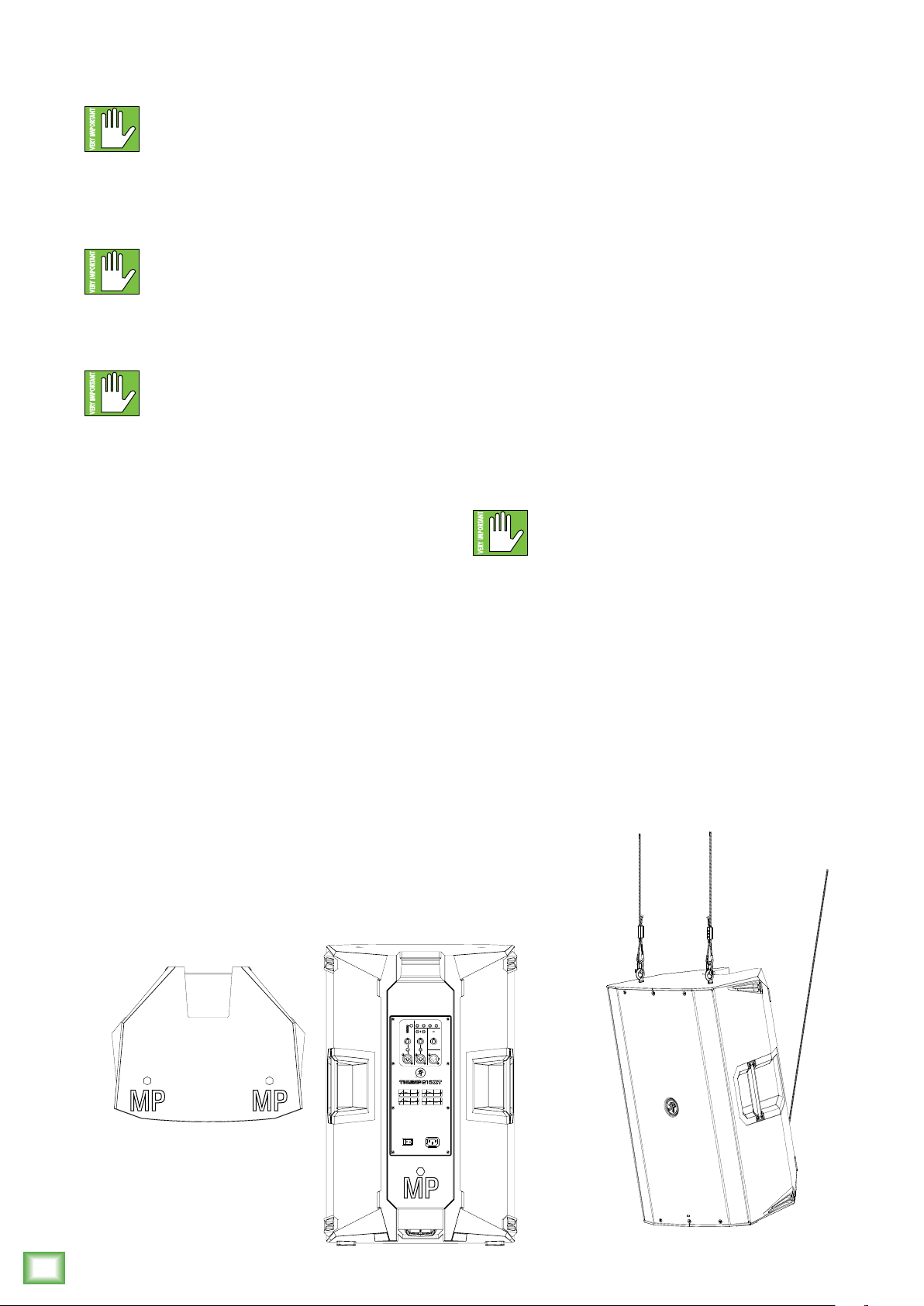
The fly points are shown below, while an example
of a flown ThumpXT is displayed below-right.
ThumpXT loudspeakers may only be flown
vertically.
Rigging Design Practices
Rigging a loudspeaker requires determining:
. The rigging methods and hardware that
meet static, shock, dynamic, and any other load
requirements for supporting the loudspeaker
from structure.
2. The design factor and required WLL (Working
Load Limit) for this support.
Rigging Hardware and Accessories
Rigging our loudspeakers will invariably require
hardware not supplied by us. Various types of
load-rated hardware are available from a variety
of third-party sources. There are a number of such
companies specializing in manufacturing hardware
for designing and installing rigging systems. Each
one of these tasks is a discipline in its own right.
Because of the hazardous nature of rigging work
and the potential liability, engage companies that
specialize in these disciplines to do the work required.
We do oer certain accessory rigging items and some
of them may be used with a variety of products. While
these accessories are intended to facilitate installation,
the wide variety of possible installation conditions and
array configurations do not permit us to determine their
suitability or load rating for any particular application.
We are not in the business of providing complete
rigging systems, either as designers, manufacturers,
or installers. It is the responsibility of the installer to
provide a properly engineered, load-certified rigging
system for supporting the loudspeaker from structure.
ThumpXT loudspeakers may be individually
flown using a PA-A2 Eyebolt Kit, part
number 205054.
We strongly recommend the following rigging
practices:
. Documentation: Thoroughly document the design
with detailed drawings and parts lists.
2. Analysis: Have a qualified professional, such
as a licensed Professional Engineer, review and
approve the design before its implementation.
3. Installation: Have a qualified professional rigger
do the installation and inspection.
4. Safety: Use adequate safety precautions
and back-up systems.
ThumpXT Fly Points
MP = Mounting Point
Thump212XT and Thump215XT 1400W Enhanced Powered Loudspeaker Series
Rigging Notes
The ThumpXT loudspeaker’s integral mounting
points are designed to support only the weight
of their own loudspeaker with suitable, external
hardware. This means that each ThumpXT
loudspeaker must be supported independently
of any other ThumpXT loudspeaker and any other
loads. At least the top two rigging points must
be used to hang each ThumpXT loudspeaker.
The rear / bottom one helps with an even
vertical hang or pullback for a down-tilt angle.
FRONT
MUSIC
FEEDBACK
OUTDOOR
VOICING MODES
LED
DUCKING
ELIMINATOR
MODE
MUSIC
LIVE
OVERLOADPAIR LINK
CLUB
MON
CH2 MAIN
CH1
GAIN VOLUME
GAIN
U U
U
LINE
LINE MIC
-
MAX
MAXMIN MIN
MAX
∞
LINE
MIC
THRU
18
VOICING MODES
MUSIC
LIVE
MON
MPMP
CLUB
100-240VAC
50-60 Hz 75W
MP
Thump212XT and Thump215XT 1400W Enhanced Powered Loudspeaker Series
Page 19

Appendix A: Service Information
Owner’s Manual
If you think your ThumpXT has a problem, please check
out the following troubleshooting tips and do your best to
confirm the problem. Visit the Support section of our website
(www.mackie.com/support) where you will find lots of useful
information such as FAQs and other documentation. You may
find the answer to the problem without having to part with
your ThumpXT.
Troubleshooting
No power
• Our favorite question: Is it plugged in? Make sure
the AC outlet is live [check with a tester or lamp].
• Our next favorite question: Is the power switch on?
If not, try turning it on.
• Make sure the line cord is securely seated in the line
cord socket and plugged all the way into the AC outlet.
• Is the power LED on the front panel illuminated?
If not, make sure the AC outlet is live. If so, refer
to “No sound” below.
• The internal AC line fuse may be blown. This is not
a user serviceable part. If you suspect the AC line
fuse is blown, please see the “Repair” section next.
Noise
• Make sure all connections to the ThumpXT are good
and sound.
• Make sure none of the signal cables are routed near
AC cables, power transformers, or other EMI-inducing
devices.
• Is there a light dimmer or other SCR-based device
on the same AC circuit as the ThumpXT? Use an
AC line filter or plug the loudspeaker into a dierent
AC circuit.
Hum
• Try disconnecting the cable connected to the input
jack. If the noise disappears, it could be a “ground
loop,” rather than a problem with the ThumpXT.
Try some of the following troubleshooting ideas:
• Use balanced connections throughout your
system for the best noise rejection.
• Whenever possible, plug all the audio
equipment’s line cords into outlets which share
a common ground. The distance between
the outlets and the common ground should
be as short as possible.
No sound
• Is the level knob for the input source turned all the way
down? Verify that all the volume controls in the system
are properly adjusted. Look at the level meter
to ensure that the mixer is receiving a signal.
• Is the signal source working? Make sure
the connecting cables are in good repair and securely
connected at both ends. Make sure the output level
control on the mixing console is turned up suciently
to drive the inputs of the speaker.
• Make sure the mixer does not have a mute on
or a processor loop engaged. If you find something
like this, make sure the level is turned down before
disengaging the oending switch.
• Has it shut down? Make sure there is at least six
inches of free space behind each ThumpXT.
Poor sound
• Is it loud and distorted? Make sure that you’re not
overdriving a stage in the signal chain. Verify that
all level controls are set properly.
• Is the input connector plugged completely into
the jack? Be sure all connections are secure.
• Are there phasing issues? The signal source should
only be connected to a single input. For example,
do not connect the L/R outputs from a mixer
to the ThumpXT channel and 2 inputs.
Do not use a Y cable to split a phone’s signal,
use both outputs of a stereo synth (which sums
to mono, anyway), etc.
Bluetooth / Linking Issues
• Sometimes a good ‘ol fashioned reset works wonders.
There are two types, sof and hard. See page 5
for more info on resetting ThumpXT.
• Try linking two ThumpXT loudspeakers together prior
to connecting via Bluetooth.
• Be sure to connect the Bluetooth device to the primary
ThumpXT loudspeaker.
Other Issues
• Please email or call Technical Support if you
are having any other issue not listed here:
o mackie.com/support-contact
o -800-898 -32
Repair
For warranty service, refer to the warranty information
on page 23.
Non-warranty service is available at a factory-authorized
service center. To locate the nearest service center,
visit www.mackie.com/support/service-locator.
Service for ThumpXTs living outside the United States
may be obtained through local dealers or distributors.
If you do not have access to our website, please call
our Tech Support department at -800-898-32 (normal
business hours, Pacific Time), to explain the problem.
They will tell you where the nearest factory-authorized
service center is located in your area.
Owner’s Manual
19
Page 20

Appendix B: Technical Information
ThumpXT Loudspeakers Specifications
Acoustic Performance
Frequency Range (–0 dB) 47 Hz – 23 kHz [Thump22XT]
40 Hz – 23 kHz [Thump25XT]
Frequency Range (–3 dB) 54 Hz – 20 kHz [Thump22XT]
47 Hz – 20 kHz [Thump25XT]
Horizontal Coverage Angle 90º
Vertical Coverage Angle 60º
Maximum SPL Peak 28 dB [Thump22XT]
29 dB [Thump25XT]
Monitor Angle 40˚
Transducers
Low Frequency 2 in / 305 mm [Thump22XT]
5 in / 38 mm [Thump25XT]
High Frequency .0 in / 25 mm polymer
compression driver
Power Amplifiers
System Power Amplification
Rated Power 400 watts peak
Low Frequency Power Amplifier
Rated Power 200 watts peak
Rated THD < %
Cooling Convection
Design Class D
High Frequency Power Amplifier
Rated Power 200 watts peak
Rated THD < %
Cooling Convection
Design Class D
System Processing
Voicing Four speaker modes
Input/Output
Input Type 2x Female XLR – /4" Balanced
TRS combo jack and /8" TRS
Mic/Line Impedance 0 k
Thump212XT and Thump215XT 1400W Enhanced Powered Loudspeaker Series
/8˝ Line Impedance 0 k
Thru Out Male XLR Balanced
Thru Out Impedance 300
Electronic Crossover
Crossover Frequency 2. kHz
Line Input Power
Detachable line cord 00–240V~, 50–60 Hz, 75W
AC Connector 3-pin IEC 250 VAC, 0 A male
Power Supply Type Switchmode
with ferrite
Balanced
Balanced
Balanced
Safety Features
Input Protection Peak and RMS limiting, power supply
and amplifier thermal protection
Display LEDs Voicing Mode, Outdoor Mode,
Music Ducking, Feedback Eliminator,
Front LED, Bluetooth Status,
Link Status, Overload
Physical Properties
Thump22XT:
Height: 24.4 in / 620 mm
Width: 4.0 in / 356 mm
Depth: 4.0 in / 356 mm
Weight: 27.6 lb / 2.5 kg
Thump25XT:
Height: 27.4 in / 696 mm
Width: 7.3 in / 439 mm
Depth: 4.0 in / 356 mm
Weight: 32.6 lb / 4.8 kg
Mounting Methods:
Floor mount, pole mount via the built-in socket on the bottom
of the cabinet [Be sure the pole is capable of supporting
the weight of the ThumpXT loudspeaker] or fly via the integrated
M0 mounting points (using M0 x .5 x 20 mm forged shoulder
eyebolts).
See pages 6–7 for more information.
Options
Thump22XT Speaker Bag P/N 2047360-09
Thump22XT Rolling Speaker Bag P/N 2047360-0
Thump25XT Speaker Bag P/N 2047360-
Thump25XT Rolling Speaker Bag P/N 2047360-2
T00 Loudspeaker Tripod Stand P/N 2052464
SPM400 Loudspeaker Pole Mount P/N 205055
PA-A Forged Shoulder Eyebolt Kit
(3 x M0 x .5 x 20 mm) P/N 003943
Disclaimer
Since we are always striving to make our products better
by incorporating new and improved materials, components,
and manufacturing methods, we reserve the right to change
these specifications at any time without notice.
The “Running Man” figure is a registered trademark of LOUD
Audio, LLC.
All other brand names mentioned are trademarks or registered
trademarks of their respective holders, and are hereby
acknowledged.
©2022 LOUD Audio, LLC. All Rights Reserved.
20
Thump212XT and Thump215XT 1400W Enhanced Powered Loudspeaker Series
Page 21
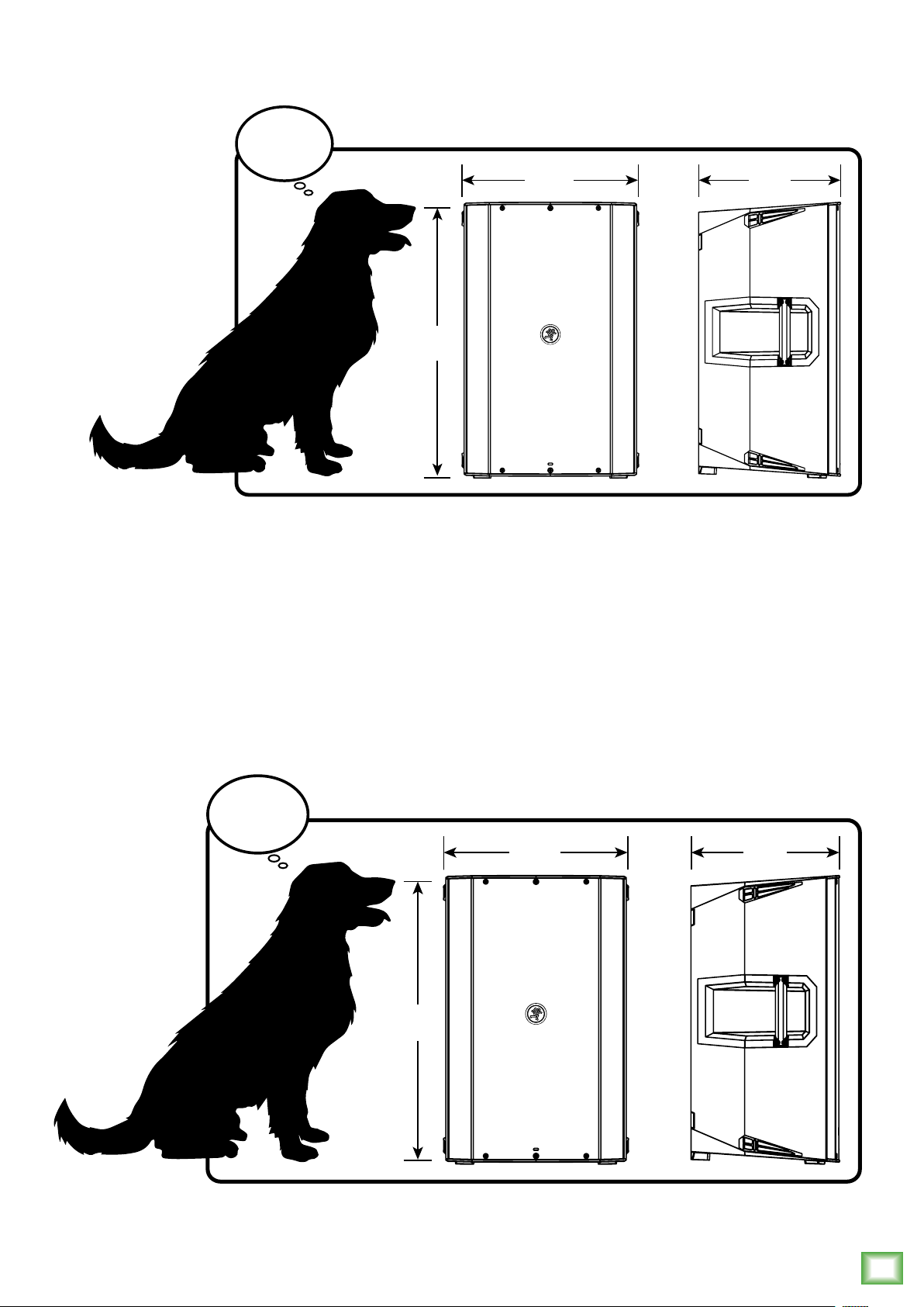
Thump22XT Dimensions
WEIGHT
27.6 lb
12.5 kg
24.4 in
620 mm
14.0 in
356 mm
Owner’s Manual
14.0 in
356 mm
Thump25XT Dimensions
WEIGHT
32.6 lb
14.8 kg
27.4 in
696 mm
17.3 in
439 mm
14.0 in
356 mm
Owner’s Manual
21
Page 22
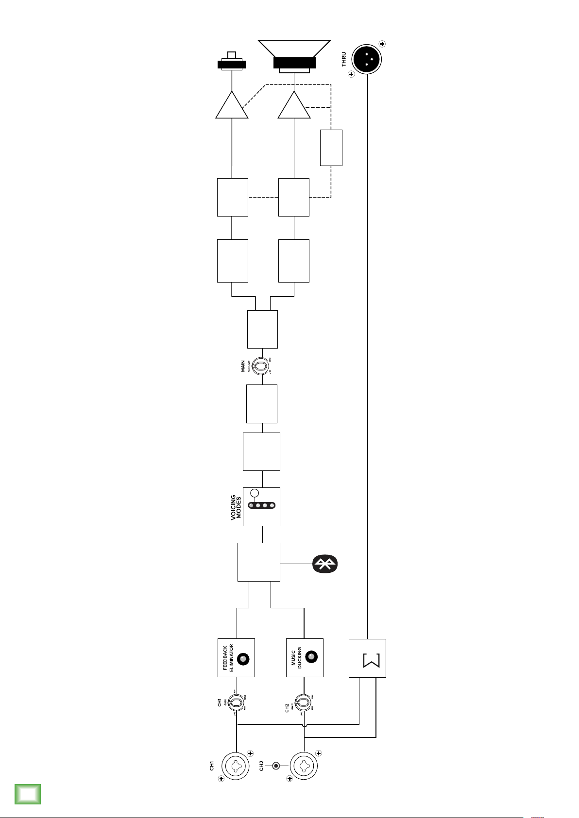
ThumpXT Block Diagram
Amp
Limiter
HF
Equalization
Amp
Thermal
Monitoring
Limiter
LF
Equalization
Crossover
Thump212XT and Thump215XT 1400W Enhanced Powered Loudspeaker Series
Level and Mute
2-band
MUSIC
2-channel
mixer with
Controls
User EQ
LIVE
CLUB
user-controlled
(app only)
(app only)
MON
(app only)
input gains
SUM
22
1/8" / 3.5mm
Thump212XT and Thump215XT 1400W Enhanced Powered Loudspeaker Series
Page 23

Limited Warranty
Please keep your sales receipt in a safe place.
This Limited Product Warranty (“Product Warranty”) is provided by LOUD Audio, LLC (“LOUD”) and is applicable to products
purchased in the United States or Canada through a LOUD-authorized reseller or dealer. The Product Warranty will not extend
to anyone other than the original purchaser of the product (hereinafer, “Customer,” “you” or “your”).
For products purchased outside the U.S. or Canada, please visit www.mackie.com to find contact information for your local
distributor, and information on any warranty coverage provided by the distributor in your local market.
LOUD warrants to Customer that the product will be free from defects in materials and workmanship under normal use
during the Warranty Period. If the product fails to conform to the warranty then LOUD or its authorized service representative
will at its option, either repair or replace any such nonconforming product, provided that Customer gives notice of the
noncompliance within the Warranty Period to the Company at: www.mackie.com or by calling LOUD technical support
at .800.898.32 (toll-free in the U.S. and Canada) during normal business hours Pacific Time, excluding weekends
or LOUD holidays. Please retain the original dated sales receipt as evidence of the date of purchase. You will need it
to obtain any warranty service.
For full terms and conditions, as well as the specific duration of the Warranty for this product, please visit www.mackie.com.
Owner’s Manual
The Product Warranty, together with your invoice or receipt, and the terms and conditions located at www.mackie.com
constitutes the entire agreement, and supersedes any and all prior agreements between LOUD and Customer related
to the subject matter hereof. No amendment, modification or waiver of any of the provisions of this Product Warranty
will be valid unless set forth in a written instrument signed by the party to be bound thereby.
Need help with the ThumpXT Loudspeakers?
• Visit www.mackie.com/support to find: FAQs, manuals, addendums, and other documents.
• Email us at: www.mackie.com/support-contact
• Telephone 1-800-898-3211 to speak with one of our splendid technical support chaps
(Monday through Friday, normal business hours, Pacific Time).
Owner’s Manual
23
Page 24

9820 North Creek Parkway #20
Bothell, WA 980 • USA
Phone: 425.487.4333
Toll-free: 800.898.32
Fax: 425.487.4337
www.mackie.com
 Loading...