

Page 1

Thump12A • Thump15A
1300W Powered Loudspeakers
OWNER’S MANUAL
Page 2
Important Safety Instructions
1. Read these instructions.
2. Keep these instructions.
3. Heed all warnings.
4. Follow all instructions.
5. Do not use this apparatus near water.
6. Clean only with a dry cloth.
7. Do not block any ventilation openings. Install in accordance
with the manufacturer’s instructions.
8. Do not install near any heat sources such as radiators, heat registers, stoves,
or other apparatus (including amplifiers) that produce heat.
9. Do not defeat the safety purpose of the polarized or grounding-type plug.
A polarized plug has two blades with one wider than the other. A grounding-type
plug has two blades and a third grounding prong. The wide blade or the third prong
are provided for your safety. If the provided plug does not fit into your outlet,
consult an electrician for replacement of the obsolete outlet.
10. Protect the power cord from being walked on or pinched particularly at plugs,
convenience receptacles, and the point where they exit from the apparatus.
11. Only use attachments/accessories specified by the manufacturer.
12. Use only with a cart, stand, tripod, bracket, or table specified
by the manufacturer, or sold with the apparatus. When a
PORTABLE CART
cart is used, use caution when moving the cart/apparatus
combination to avoid injury from tip-over.
13. Unplug this apparatus during lightning storms or when
unused for long periods of time.
14. Refer all servicing to qualified service personnel. Servicing is
required when the apparatus has been damaged in any way, such as power-supply
cord or plug is damaged, liquid has been spilled or objects have fallen into the
apparatus, the apparatus has been exposed to rain or moisture, does not operate
normally, or has been dropped.
15. This apparatus shall not be exposed to dripping or splashing, and no object filled
with liquids, such as vases or beer glasses, shall be placed on the apparatus.
16. Do not overload wall outlets and extension cords as this can result in a risk of fire
or electric shock.
17. This apparatus has been designed with Class-I construction and must be
connected to a mains socket outlet with a protective earthing connection
(the third grounding prong).
18. This apparatus has been equipped with a rocker-style AC mains power switch. This
switch is located on the rear panel and should remain readily accessible to the user.
19. The MAINS plug or an appliance coupler is used as the disconnect device,
so the disconnect device shall remain readily operable.
Thump12A • Thump15A Powered Loudspeakers
CAUTION
RISK OF ELECTRIC SHOCK! DO NOT OPEN!
CAUTION: TO REDUCE THE RISK OF ELECTRIC SHOCK DO NOT
REMOVE COVER (OR BACK). NO USER-SERVICEABLE PARTS INSIDE.
REFER SERVICING TO QUALIFIED PERSONNEL.
The lightning flash with arrowhead symbol within
an equilateral triangle is intended to alert the user
to the prescence of uninsulated “dangerous voltage”
within the product’s enclosure, that may be of significant
magnitude to constitute a risk of electric shock to persons.
The exclamation point within an equilateral triangle is
intended to alert the user of the prescence of important
operating and maintaining (servicing) instructions in the
literature accompanying the appliance.
WARNING
20. NOTE: This equipment has been tested and found to comply with the limits
for a Class B digital device, pursuant to part 15 of the FCC Rules. These limits
are designed to provide reasonable protection against harmful interference
in a residential installation. This equipment generates, uses, and can radiate
radio frequency energy and, if not installed and used in accordance with the
instructions, may cause harmful interference to radio communications. However,
there is no guarantee that interference will not occur in a particular installation.
If this equipment does cause harmful interference to radio or television reception,
which can be determined by turning the equipment off and on, the user is
encouraged to try to correct the interference by one or more of the following
measures:
• Reorient or relocate the receiving antenna.
• Increase the separation between the equipment and the receiver.
• Connect the equipment into an outlet on a circuit different from
that to which the receiver is connected.
• Consult the dealer or an experienced radio/TV technician for help.
CAUTION: Changes or modifications to this device not expressly approved by
LOUD Technologies Inc. could void the user's authority to operate the equipment
under FCC rules.
21. This apparatus does not exceed the Class A/Class B (whichever is applicable)
limits for radio noise emissions from digital apparatus as set out in the radio
interference regulations of the Canadian Department of Communications.
ATTENTION — Le présent appareil numérique n’émet pas de bruits radioélectriques
dépassant las limites applicables aux appareils numériques de class A/de class B
(selon le cas) prescrites dans le réglement sur le brouillage radioélectrique édicté
par les ministere des communications du Canada.
22. Exposure to extremely high noise levels may cause permanent hearing loss.
Individuals vary considerably in susceptibility to noise-induced hearing loss, but
nearly everyone will lose some hearing if exposed to sufficiently intense noise
for a period of time. The U.S. Government’s Occupational Safety and Health
Administration (OSHA) has specified the permissible noise level exposures shown
in the following chart.
According to OSHA, any exposure in excess of these permissible limits could result
in some hearing loss. To ensure against potentially dangerous exposure to high
sound pressure levels, it is recommended that all persons exposed to equipment
capable of producing high sound pressure levels use hearing protectors while the
equipment is in operation. Ear plugs or protectors in the ear canals or over the
ears must be worn when operating the equipment in order to prevent permanent
hearing loss if exposure is in excess of the limits set forth here:
Duration,
per day in
hours
8 90 Duo in small club
6 92
4 95 Subway Train
3 97
2 100 Very loud classical music
1.5 102
1 105 John screaming at Troy about deadlines
0.5 110
0.25 or less 115 Loudest parts at a rock concert
Sound Level dBA,
Slow Response
Typical Example
WARNING — To reduce the risk of fire or electric
shock, do not expose this apparatus to rain or moisture.
CAUTION — To prevent electric shock hazard, do not
connect to mains power supply while grille is removed.
Correct disposal of this product: This symbol indicates that this product should not be disposed of with your household
waste, according to the WEEE directive (2012/19/EU) and your national law. This product should be handed over to
an authorized collection site for recycling waste electrical and electronic equipment (EEE). Improper handling of this type
of waste could have a possible negative impact on the environment and human health due to potentially hazardous substances
that are generally associated with EEE. At the same time, your cooperation in the correct disposal of this product will
contribute to the effective usage of natural resources. For more information about where you can drop off your waste
equipment for recycling, please contact your local city office, waste authority, or your household waste disposal service.
2
Thump12A • Thump15A Powered Loudspeakers
Laite on liitettävä suojakoskettimilla varustettuun pistorasiaan.
Apparatet må tilkoples jordet stikkontakt.
Apparaten skall anslutas till jordat uttag.
Page 3

Contents Features
Owner’s Manual
Important Safety Instructions .................................. 2
Contents ................................................................. 3
Features ................................................................. 3
Introduction ............................................................ 4
How To Use This Manual ......................................... 4
Getting Started ....................................................... 4
Things To Remember ................................................ 4
Hookup Diagrams .................................................... 5
Thump12A / Thump15A: Rear Panel Features ........ 10
1. Power Connection ....................................... 10
2. Power Switch ............................................. 10
3. XLR and 1/4" Combo Inputs ........................ 10
4. Gain Knobs ................................................. 11
5. Mix Out Output .......................................... 11
6. Main Knob .................................................. 11
7. Speaker Mode ............................................ 11
8. Main LED Switch / Limit LED ....................... 12
Protection Circuitry ............................................... 12
Limiting .......................................................... 12
Overexcursion Protection ................................ 12
Thermal Protection .......................................... 12
AC Power ............................................................. 12
Care and Maintenance ........................................... 12
Placement ............................................................. 13
Room Acoustics ..................................................... 13
• Power
• 1300 Watts of high quality, dynamic peak
power amplification
• Switch-mode power supply with Power
Factor Correction (PFC) for optimal
performance in any AC line condition
• Drivers
• 12" low frequency, high output driver
for deep bass response [Thump12A]
• 15" low frequency, high output driver
for deep bass response [Thump15A]
• 1.4" titanium dome compression driver
for extended high frequency response
• Dynamic DSP bass boost delivers maximum
Thump regardless of output
• Complete system protection and performance
optimization
• Independent HF & LF RMS limiters protect
drivers from excess heat and damage
• Independent HF & LF peak limiters
eliminate clipping and distortion
• Mackie 2-channel Wide-Z mixer and XLR though
for daisy chain and subwoofer systems
• Simple, flexible user rear panel control
• Four application specific speaker modes
• Independent channel and master controls
• Front LED on/off
Appendix A: Service Information ............................ 15
Appendix B: Technical Information .......................... 16
Thump12A / Thump15A Dimensions ................ 17
Thump12A / Thump15A Frequency Response ... 18
Thump12A / Thump15A Block Diagram ............ 19
Limited Warranty .................................................. 20
Please write the serial numbers here for future
reference (i.e., insurance claims, tech support,
return authorization, make dad proud, etc.)
Purchased at:
Date of purchase:
• Durable, lightweight molded enclosure
• Dual symmetrical monitor angles
• Two full grip side handles plus top carry
handle and bottom rear lift pocket
• Rugged powder coated perforated steel
grille with acoustically transparent
cosmetic mesh
• 29.1 lb / 13.2 kg
• 34.8 lb / 15.8 kg
Like us
Follow us
Part No. SW1200 Rev. A 06/17
©2017 LOUD Technologies Inc. All Rights Reserved.
Watch our dang videos
Owner’s Manual
3
Page 4

Introduction
Getting Started
Delivering proven, chest-thumping low-end
with Dynamic Bass Response™ technology in
all-new, professional enclosures, the 1300W Thump™
loudspeakers take the series to a whole new level.
Get maximum versatility with built-in mixers and
application-specific speaker modes. And for maximum
room-shaking low-end, pair your Thump speakers
with the 1200W Thump18S Subwoofer.
Redesigned from the ground up, these are our most
flexible and powerful Thump loudspeakers ever with
the class-leading performance you need.
The following steps will help you set up the
loudspeakers quickly.
1. Make all initial connections with the power
switches OFF on all equipment. Make sure the master
volume, level and gain controls are all the way down.
2. If using a subwoofer, connect the outputs
from the mixing console (or other signal source)
to the inputs on the loudspeaker, then connect
the mix out to the inputs of the subwoofers. Make
sure the subwoofer’s gain knob is set to “U” (unity gain).
3. If not using a subwoofer, connect the outputs
from the mixing console (or other signal source)
to the inputs on the rear panel of the loudspeakers.
4. Make sure the loudspeaker’s gain knobs are set
to (or near) “line”.
5. Push the line cord securely into the subwoofer’s/
loudspeaker’s IEC connectors and plug the other ends
into grounded AC outlets. The subwoofer/loudspeaker
may accept the appropriate voltage as indicated near
the IEC connector.
How to Use This Manual:
After this introduction, a getting started guide will
help you get things set up fast. The hookup diagrams
show some typical Thump12A and Thump15A setups,
Thump12A • Thump15A Powered Loudspeakers
including some that involve the Thump18S subwoofer.
This icon marks information that is critically
important or unique to the subwoofer. For
your own good, read and remember them.
6. Turn the mixer (or other signal source) on.
7. Turn the subwoofer on.
8. Turn the loudspeakers on.
9. Start the signal source and raise the mixer’s
main L/R fader up to a comfortably loud listening level.
Things to Remember:
• Never listen to loud music for prolonged periods.
Please see the Safety Instructions on page 2 for
information on hearing protection.
• As a general guide, the mixer (or other signal
source) should be turned on first, subwoofers
next, and Thump loudspeakers last. As such,
the Thump loudspeakers should also be turned off
first, followed by the subwoofers, then the mixer.
This will reduce the possibility of any turn-on
or turn-off thumps and other noises generated
by any upstream equipment from coming out of
the speakers.
• Save the shipping boxes and packing materials!
You may need them someday. Besides, the
cats will love playing in them and jumping out at
you unexpectedly. Remember to pretend like you
are surprised!
• Save your sales receipt in a safe place.
4
Thump12A • Thump15A Powered Loudspeakers
Page 5
Hookup Diagrams
Owner’s Manual
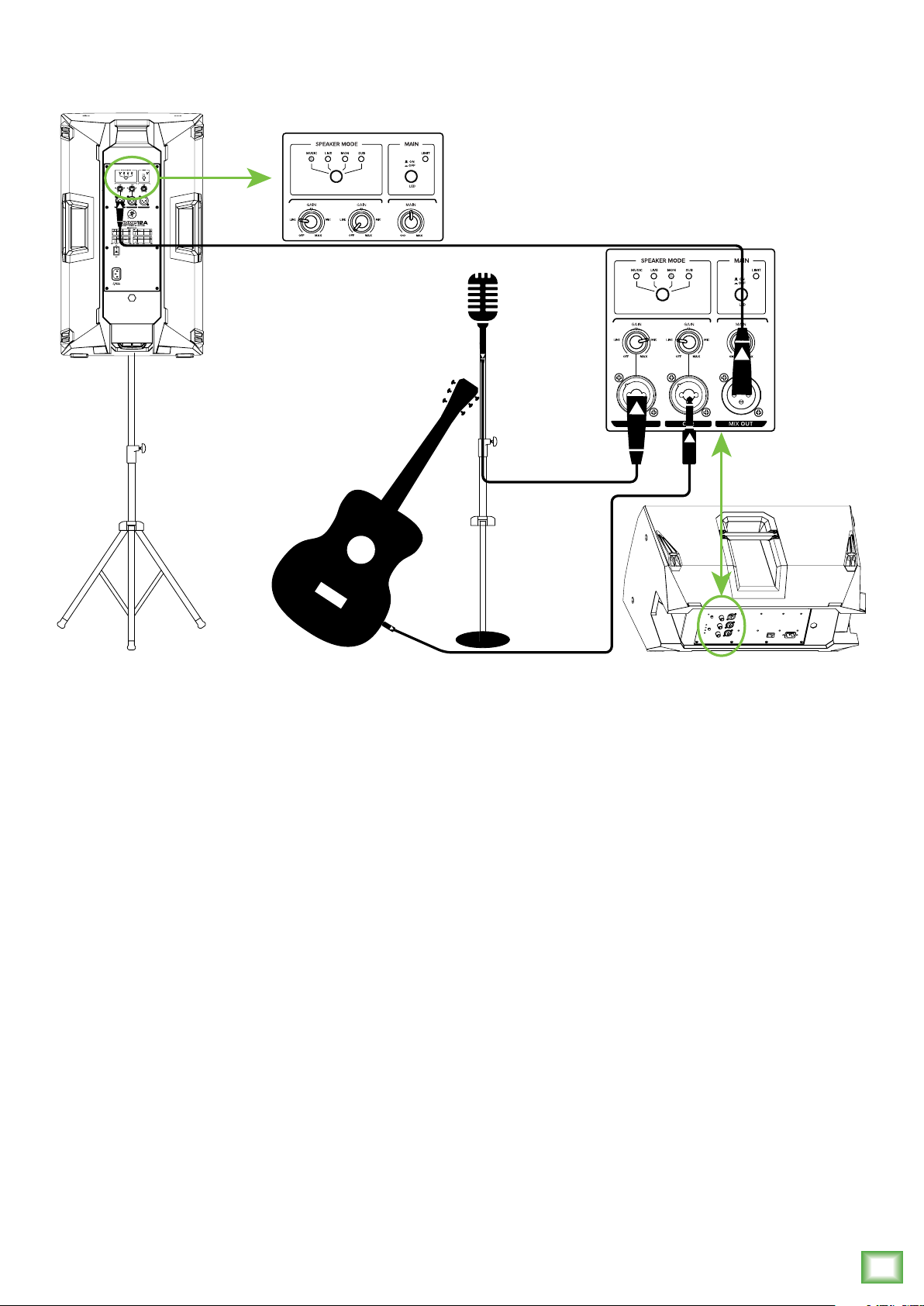
Thump loudspeakers are the perfect tool for singer-songwriters touring the local coffee shops.
Bring your favorite axe and mic, Thump loudspeakers and cables and power cords.
In this example, a dynamic microphone is connected to the channel 1 input of a Thump12A
loudspeaker, used for monitoring purposes. Be sure that the gain knob is set to “mic” in order to
get an extra boost for the mic. If anything other than a microphone is attached to a channel input,
make sure the gain knob is set to anything other than “mic” [“line” is a safe bet]. From there,
adjust the gain as described on page 11.
Now grab your axe and plug it directly into the channel 2 input. Or if you use effects, connect
the guitar to the effects input and another cable from the effects output to the channel 2 input.
Set the channel two gain knob to “line”.
Another Thump12A loudspeaker will be used for the main PA. Simply connect a cable from the Thump12A monitor’s MIX OUT jack to the Thump12A PA’s channel 1 input [gain knob set to “line”].
For the output, you will want to set a speaker mode, described in detail on page 11. For this type of
setup, Music works well for the main Thump12A. However, don’t count out the Live mode! It has a nice
low cut and a brilliant high end. Select the Monitor mode for the Thump12A monitor.
Owner’s Manual
5
Page 6
Hookup Diagrams continued...
LINE
HI-Z
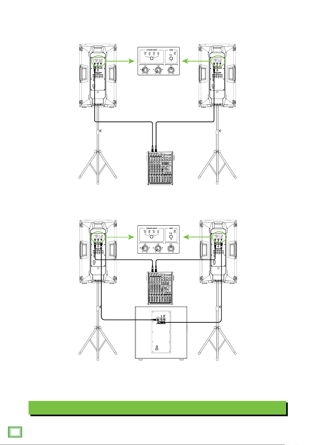
In this example, a ProFX8v2 mixer is connected directly to two Thump12A loudspeakers. It is the perfect
setup for a small club. Simply connect the L/R outputs of the ProFX8v2 mixer
to the CH1 input of each
Thump12A loudspeaker. Don’t forget to set the CH1 gains to ‘Line’ and the Speaker Modes to Music!
LINE
Thump12A • Thump15A Powered Loudspeakers
HI-Z
If you desire a little more boom, add a Thump18S subwoofer to the mix.
Here, the L/R outputs
of a ProFX8v2 mixer are connected directly to the CH1 inputs of each Thump12A loudspeaker.
Then the Mix Out of each loudspeaker is connected to the channel A and B inputs of a single
Thump18S subwoofer. Don’t forget to set the CH1 gains to ‘Line’ and the Speaker Modes to Sub.
Small Club System
6
Thump12A • Thump15A Powered Loudspeakers
Page 7
Hookup Diagrams continued...
Owner’s Manual
MONITORC MONITORBMONITOR
USB
REC SRC
SELECT
2-TRACK
INPUTS 1/2
+18VDC
POWER
1.5A
PHONES
A
L
L
L
R
R
R
BAL / UNBAL
BAL / UNBAL
BAL / UNBAL BAL / UNBALBAL / UNBAL
OUTPUTS
AUX
+4dB
AMP
-10dB
R
BAL / UNBALBAL / UNBAL
MIX
+4dB
-10dB
INT
EXT
LRL
MIC
TALKBACK
FOOTSWITCH
L
(MONO)
R
BAL / UNBAL
CUE IN
L
L
(MONO)
(MONO)
R
R
SOURCES INPUTS
1(L)3/45/62-TRACKSTUDIO/
2(R)
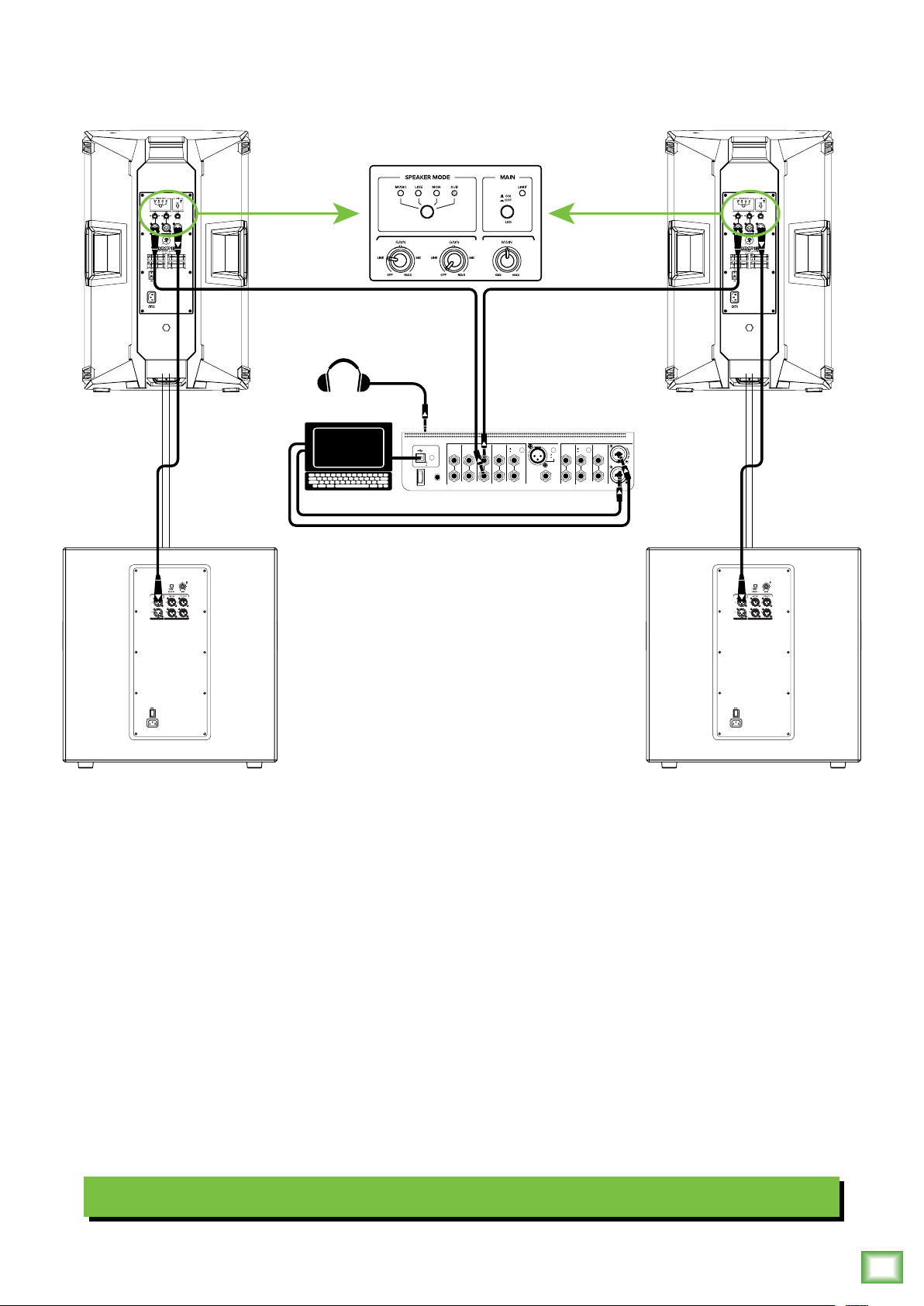
Perhaps you’re a DJ playing bumpin’ tunes in the middle of the night to a crowd that’s groovin’
and dancin’ to your fine selection.
In this example, a laptop is connected to the channel 1 and 2 inputs of a Big Knob Studio+ and a set of
headphones are connected to the phones jack.
The L/R Monitor A outputs of the Big Knob Studio+ are connected directly to the CH1 inputs of each
Thump15A loudspeaker.
The Mix Out of each loudspeaker is connected to the channel A input of each Thump18S subwoofer.
The CH1 gains of both loudspeakers may be set to ‘Line’ and the Speaker Modes on both to Sub.
DJ System
Owner’s Manual
7
Page 8

Hookup Diagrams continued...
To next
Thump
loudspeaker
input
To next
Thump
loudspeaker
input
Main
Outs
1402VLZ4 Mixer
To next
Thump
loudspeaker
input
Thump12A • Thump15A Powered Loudspeakers
Thump loudspeakers may be daisy-chained via the male XLR connector labeled “MIX OUT”.
Simply plug the signal source (i.e., mixer output or microphone) into the input jack(s), and patch
that loudspeaker’s mix out jack to the next loudspeaker’s input jack, and so on, daisy-chaining
multiple Thump loudspeakers.
If daisy-chaining via mixer, set the gain knobs to Line. If daisy-chaining via microphone, set the gain
knobs to Mic. See above for visual representations of daisy-chaining.
Daisy-Chaining Multiple Thump Loudspeakers
8
Thump12A • Thump15A Powered Loudspeakers
Page 9

Hookup Diagrams continued...
Owner’s Manual
Here’s how to set up a large club system. In this example, the L/R outputs of a DL1608 mixer are
connected directly to the CH1 inputs of a pair of Thump15A loudspeakers. The CH1 gains of these
PA loudspeakers may be set to ‘Line’ and the Speaker Modes on both to Sub.
The Mix Out of each loudspeaker is then connected to the channel A input of a pair of Thump18S
subwoofers.From here, the channel A full range outputs of the two outer Thump18S subwoofers
are connected directly to the channel A inputs of another set of Thump18S subwoofers. Talk about
beefy low end!
The aux 1 and aux 2 sends from the mixer are connected directly to the CH1 inputs of a pair
of Thump12A loudspeakers to be used as monitors for the band. The CH1 gains of the the
monitor loudspeakers may be set to ‘Line’ and the Speaker Modes on both to Monitor.
Large Club System
Owner’s Manual
9
Page 10

Thump12A / Thump15A Loudspeakers: Rear Panel Features
2
3. XLR and 1/4" Combo Inputs
Both input channels may accept a balanced
mic signal using an XLR connector. They are wired
as follows, according to standards specified by the
7
4
3
8
6
5
AES (Audio Engineering Society).
XLR Balanced Wiring:
Pin 1 = Shield (ground)
Pin 2 = Positive (+ or hot)
Pin 3 = Negative (– or cold)
SHIELD
HOT
3
COLD
1
3
2
In addition to accepting a balanced mic signal using
an XLR connector, these input channels may also accept
1/4" line-level signals driven by balanced or unbalanced
sources.
1
SHIELD
COLD
HOT
1 2
1. Power Connection
This is a standard 3-prong IEC power connector.
Connect the detachable power cord (included in
the packaging with the loudspeaker) to the power
receptacle, and plug the other end of the power
Thump12A • Thump15A Powered Loudspeakers
cord into an AC outlet.
Make sure that the AC power is matched to
the AC power indicated on the rear panel
(below the IEC receptacle).
Disconnecting the plug’s ground pin is
dangerous. Don’t do it!
2. Power Switch
Press the top of this rocker switch inwards to turn on
the loudspeaker. Press the bottom of this rocker switch
inwards to turn off the loudspeaker.
As a general guide, the mixer (or other
signal source) should be turned on first,
subwoofers next, and loudspeakers last.
As such, the loudspeakers should also be turned
off first, followed by the subwoofers, then the mixer.
This will reduce the possibility of any turn-on or
turn-off thumps and other noises generated by any
upstream equipment from coming out of the speakers.
Additionally, both input channels may accept Hi-Z
sources (such as guitars) via the 1/4" input without the
need for a separate DI box.
To connect balanced lines to these inputs, use
a 1/4" Tip-Ring-Sleeve (TRS) plug. “TRS” stands for
Tip-Ring-Sleeve, the three connection points available
on a stereo 1/4" or balanced phone jack or plug. TRS
jacks and plugs are used for balanced signals and are
wired as follows:
1/4" TRS Balanced Mono Wiring:
Sleeve = Shield
Tip = Hot (+)
Ring = Cold (–)
TIPSLEEVE
SLEEVERING
TIP
RING
RING
TIP
SLEEVE
To connect unbalanced lines to these inputs, use
a 1/4" mono (TS) phone plug, wired as follows:
1/4" TS Unbalanced Mono Wiring:
Sleeve = Shield
Tip = Hot (+)
SLEEVE
TIP
TIPSLEEVE
TIP
SLEEVE
NEVER connect the output of an amplifier
directly to a Thump’s input jack. This could
damage the input circuitry!
10
Thump12A • Thump15A Powered Loudspeakers
Page 11

Thump12A / Thump15A Loudspeakers: Rear Panel Features continued...
6. Main Knob
The level knob adjusts the overall signal level at the
input to the built-in power amplifiers. It ranges from Off
) to MAX (maximum gain), with unity gain at the
(–
8
7
center position (12 o’clock).
• Thump loudspeakers are designed to operate with
a +4 dBu signal when the main knob is at the center
position.
Owner’s Manual
4
6
5
4. Gain Knobs
The gain knobs adjust the input sensitivity of the
mic/line inputs. This allows signals from the outside
world to be adjusted to run through each channel at
optimal internal operating levels.
There is –
(off), ramping up to 50 dB of gain fully up (max).
5. Mix Out
This is a male XLR-type connector that produces
exactly the same signal that is connected to the input
jacks. Use it to daisy-chain several Thump loudspeakers
together off the same signal source(s).
They are wired as follows, according to standards
specified by the AES (Audio Engineering Society):
dB of gain with the knob fully down
If connecting mixer outputs to loudspeaker
inputs, set the gain knob to 10:00 [“Line”]
for optimal sound and performance.
• Thump loudspeakers may accept up to a +20 dBu
signal by turning down the main knob accordingly.
Turning the main knob past center position will provide
enough gain to connect a microphone directly.
7. Speaker Mode
Here you are able to change the loudspeaker’s
speaker mode to tailor it to best suit your particular
application. There are four modes: Music, Live,
Monitor and Sub. Press the speaker mode button
repeatedly until the LED of the speaker mode
you desire is illuminated. Refer to the Frequency
Response graphs on page 18 for further information.
MUSIC Speaker Mode – This mode is full range,
but focuses on increased bass and brilliant high
frequencies. This is the place to start for most DJ /
music playback applications.
LIVE Speaker Mode – This mode features a low
frequency roll-off to get rid of unwanted thumps
and adds boost and sparkle to mid-range and high
frequencies. This plug-and-play mode is perfect for
singer-songwriters.
MON(itor) Speaker Mode – This mode features a
low frequency roll-off and a reduction around 2 kHz to
ensure maximum gain before feedback in monitor
applications.
Balanced XLR Output Connector
Pin 1 – Shield (ground)
Pin 2 – Positive (+ or hot)
Pin 3 – Negative (– or cold)
SHIELD
1
3
COLD
Balanced XLR Output Connector
2
HOT
1
3
2
SHIELD
COLD
HOT
See page 8 to learn more about daisy-chaining Thump
loudspeakers.
(With) SUB Speaker Mode – This mode rolls off the
low end of the ThumpA loudspeaker to match properly
with the Thump18S subwoofer.
Owner’s Manual
11
Page 12

Thump12A / Thump15A Loudspeakers: Rear Panel Features continued...
8. Main LED Switch / Limit LED
The LED on the front of the Thump loudspeaker
illuminates when this switch is disengaged and
AC power is available at the mains input. Engage
the switch if you do not want the front panel LED
to illuminate.
Thump loudspeakers have a built-in limiter that
helps to prevent the amplifier outputs from clipping
or overdriving the transducers. The limit indicator
illuminates amber when the limiter is activated.
It’s okay for it to blink yellow occasionally, but if it
blinks frequently or lights continuously, turn down
the gain knob(s) until it only blinks occasionally.
Excessive limiting may lead to overheating,
which in turn trips the thermal protect
circuitry and interrupts the performance.
See ‘Thermal Protection’ to the right for more
information.
Protection Circuitry
Thump loudspeakers employ a built-in limiter for
less distortion at peak levels. A dynamic bass response
circuit provides optimal low frequency response
regardless of overall output level. Additional protection
includes automatic thermal shutdown should the amp
overheat. However, with Class-D amp technology, which
is highly-efficient, this should never be a problem.
The protection circuits are designed to
protect the loudspeakers under reasonable
and sensible conditions. Should you choose
to ignore the warning signs [e.g. excessive distortion],
Thump12A • Thump15A Powered Loudspeakers
you can still damage the speaker in the loudspeaker
by overdriving it past the point of amplifier clipping.
Such damage is beyond the scope of the warranty.
Thermal Protection
All amplifiers produce heat. Thump loudspeakers are
designed to be efficient both electrically and thermally.
In the unlikely event of the amplifier overheating, a
built-in thermal switch will activate, muting the signal.
When the amplifier has cooled down to a safe
operating temperature, the thermal switch resets
itself, and the Thump loudspeaker resumes normal
operation.
If the thermal switch activates, try turning down
the level control a notch or two on the mixing console
(or the back of the loudspeaker) to avoid overheating
the amplifier. Be aware that direct sunlight and/or
hot stage lights may be the culprit of an amplifier
overheating.
AC Power
Be sure the Thump loudspeaker is plugged into
an outlet that is able to supply the correct voltage
specified for your model. It will continue to operate
at lower voltages, but will not reach full power. Be sure
the electrical service can supply enough amperage for
all the components connected to it.
We recommend that a stiff (robust) supply of AC
power be used because the amplifiers place high
current demands on the AC line. The more power that
is available on the line, the louder the speakers will play
and the more peak output power will be available for
a cleaner, punchier bass. A suspected problem of “poor
bass performance” is often caused by a weak AC supply
to the amplifiers.
Never remove the ground pin on the power
cord or any other component of the Thump
loudspeaker. This is very dangerous.
12
Limiting
The driver has its own compression circuit which
helps protect it from damaging transient peaks.
The compressor is designed to be transparent and
is not noticeable under normal operating conditions.
Overexcursion Protection
A subsonic filter circuit just prior to the power
amplifier prevents ultra-low frequencies from being
amplified. Excessive low-frequency energy can damage
the woofer by causing it to “bottom out,” also know
as overexcursion, which is equivalent to a mechanical
form of clipping.
Thump12A • Thump15A Powered Loudspeakers
Care and Maintenance
Your Thump loudspeakers will provide many years of
reliable service if you follow these guidelines:
• Avoid exposing the loudspeakers to moisture.
If they are set up outdoors, be sure they are
under cover if rain is expected.
• Avoid exposure to extreme cold (below
freezing temperatures). If you must operate
the loudspeakers in a cold environment, warm
up the voice coils slowly by sending a low-level
signal through them for about 15 minutes prior
to high-power operation.
• Use a dry cloth to clean the cabinets. Only do
this when the power is turned off. Avoid getting
moisture into any of the openings of the
cabinet, particularly where the drivers are
located.
Page 13

Owner’s Manual
Placement
Thump loudspeakers are designed to sit on the floor
or stage as the main PA or as monitors. They may also be
pole-mounted via the built-in socket on the bottom of
the cabinet. Be sure the pole is capable of supporting
the weight of the loudspeaker. The SPM200 is a great
option when using a subwoofer.
WARNING: These Thump loudspeakers do
not have rigging points and are not suitable
for rigging. NEVER attempt to suspend
a Thump loudspeaker by its handles.
Check to make sure that the support surface
(e.g. floor, etc.) has the necessary mechanical
characteristics to support the weight of the
loudspeaker(s).
When pole-mounting loudspeakers, be sure that they
are stabilized and secured from falling over or being
accidentally pushed over. Failure to follow these
precautions may result in damage to the equipment,
personal injury, or death.
As with any powered components, protect them from
moisture. Avoid installing the loudspeaker in places
exposed to harsh weather conditions. If you are setting
them up outdoors, make sure they are under cover if
you expect rain.
Thump loudspeakers are NOT designed to array
horizontally. If you feel you must put two speakers
side-by-side, you should have a good understanding
of the relationship between the splay angle (the angle
between the facing sides of the cabinets) and frequency
cancellation effects between cabinets.
When two cabinets are positioned side-by-side
such that the rear-angled faces of the enclosures
are parallel, the splay angle will be 90º. This matches
the 90˚ horizontal coverage pattern of each individual
loudspeaker; the interference between the two cabinets
will be minimized, but the total coverage of 180˚ may
be too wide for some applications. The mid and high
frequencies may also be reduced for those in the center
who are too close to the loudspeakers.
Room Acoustics
Thump loudspeakers are designed to sound fantastic
in nearly every application.
But, room acoustics play a crucial role in the overall
performance of a sound system. However, the wide
high-frequency dispersion of the Thump loudspeakers
helps to minimize the problems that typically arise.
Top
0
90
900 Dispersion
up to 23 kHz
Here are some additional placement tips to help
overcome some typical room problems that might arise:
• Placing loudspeakers in the corners of a room
increases the low frequency output and can
cause the sound to be muddy and indistinct.
• Placing loudspeakers against a wall increases
the low frequency output, though not as much
as corner placement. However, this is a good
way to reinforce the low frequencies, if so
desired.
• Avoid placing the speakers directly on a
hollow stage floor. A hollow stage can resonate
at certain frequencies, causing peaks and dips
in the frequency response of the room. It is
better to place them on a sturdy stand designed
to handle the weight of the loudspeaker.
Reducing the splay angle will reduce the total
horizontal coverage, but it also creates an area both
speakers are covering. Instead of a nearfield hole,
this will cause comb-filtering effects in the frequency
response in the overlapping area. The smaller the splay
angle, the more energy will be delivered on-axis, but the
comb-filtering effects will get worse at the same time.
To reiterate, though, we strongly suggest
NOT arraying these loudspeakers horizontally.
Experimentation and experience will help you find
the right balance for your application.
• Position the loudspeakers so the highfrequency drivers are two to four feet above
ear level for the audience (making allowances
for an audience that may be standing/dancing
in the aisles). High frequencies are highly
directional and tend to be absorbed much
easier than lower frequencies. By providing
direct line-of-sight from the loudspeakers
to the audience, you increase the overall
brightness and intelligibility of the sound
system.
Owner’s Manual
13
Page 14

• Highly reverberant rooms, like many
gymnasiums and auditoriums, are a
nightmare for sound system intelligibility.
Multiple reflections off the hard walls, ceiling,
and floor play havoc with the sound. Depending
on the situation, you may be able to take some
steps to minimize the reflections, such as
putting carpeting on the floors, closing
draperies to cover large glass windows, or
hanging tapestries or other materials on the
walls to absorb some of the sound.
However, in most cases, these remedies are not
possible or practical. So what do you do?
Making the sound system louder generally
doesn’t work because the reflections become
louder, too. The best approach is to provide as
much direct sound coverage to the audience
as possible. The farther away you are from
the speaker, the more prominent will be the
reflected sound.
Use more speakers strategically placed so they
are closer to the back of the audience. If the
distance between the front and back speakers
is more than about 100 feet, you should use a
delay processor to time-align the sound. (Since
sound travels about 1 foot per millisecond, it
takes about 1/10 of a second to travel 100 feet.)
Keep in mind that the speaker mode is a great way
to compensate for some of these issues. See page 11 for
more information.
Thump12A • Thump15A Powered Loudspeakers
14
Thump12A • Thump15A Powered Loudspeakers
Page 15

Appendix A: Service Information
Owner’s Manual
If you think your Thump loudspeaker has a problem,
please check out the following troubleshooting tips and
do your best to confirm the problem. Visit the Support
section of our website (www.mackie.com/support)
where you will find lots of useful information such
as FAQs and other documentation. You may find the
answer to the problem without having to part with your
loudspeaker.
Troubleshooting
No power
• Our favorite question: Is it plugged in? Make sure
the AC outlet is live [check with a tester or lamp].
• Our next favorite question: Is the power switch
on? If not, try turning it on.
• Make sure the line cord is securely seated in the
line cord socket and plugged all the way into the
AC outlet.
Poor sound
• Is it loud and distorted? Make sure that you’re not
overdriving a stage in the signal chain. Verify that
all level controls are set properly.
• Is the input connector plugged completely into
the jack? Be sure all connections are secure.
Noise
• What is the position of the gain knob? It should
be at (or near) “mic” when a mic is connected
and at (or near) “line” when a line-level signal
is connected. It should be “off” for all unused
inputs.
• Make sure all connections to the active
loudspeakers are good and sound.
• Make sure none of the signal cables are routed
near AC cables, power transformers, or other
EMI-inducing devices.
• Is the power LED on the front panel illuminated?
If not, make sure the AC outlet is live. If so, refer
to “No sound” below.
• The internal AC line fuse may be blown. This is
not a user serviceable part. If you suspect the
AC line fuse is blown, please see the "Repair"
section next.
No sound
• Is the level knob for the input source turned all
the way down? Verify that all the volume controls
in the system are properly adjusted. Look at the
level meter to ensure that the mixer is receiving
a signal.
• Is the signal source working? Make sure the
connecting cables are in good repair and securely
connected at both ends. Make sure the output
level control on the mixing console is turned up
sufficiently to drive the inputs of the speaker.
• Make sure the mixer does not have a mute on or a
processor loop engaged. If you find something like
this, make sure the level is turned down before
disengaging the offending switch.
• Has it shut down? Make sure there is at least
six inches of free space behind each Thump
loudspeaker.
• Is there a light dimmer or other SCR-based
device on the same AC circuit as the Thump
loudspeaker? Use an AC line filter or plug the
loudspeaker into a different AC circuit.
Hum
• Try disconnecting the cable connected to the
input jack. If the noise disappears, it could be
a “ground loop,” rather than a problem with the
Thump loudspeaker. Try some of the following
troubleshooting ideas:
• Use balanced connections throughout your
system for the best noise rejection.
• Whenever possible, plug all the audio
equipment’s line cords into outlets which
share a common ground. The distance
between the outlets and the common ground
should be as short as possible.
Repair
For warranty service, refer to the warranty
information on page 20.
Non-warranty service is available at a factoryauthorized service center. To locate the nearest
service center, visit www.mackie.com/support/servicelocator. Service for Thump loudspeakers living outside
the United States may be obtained through local dealers
or distributors.
If you do not have access to our website, please
call our Tech Support department at 1-800-898-3211
(normal business hours, Pacific Time), to explain the
problem. They will tell you where the nearest factoryauthorized service center is located in your area.
Owner’s Manual
15
Page 16

Appendix B: Technical Information
Thump12A / Thump15A Loudspeakers Specifications
Acoustic Performance
Frequency Range (–10 dB): 50 Hz – 23 kHz [Thump12A]
32 Hz – 23 kHz [Thump15A]
Frequency Range (–3 dB): 57 Hz – 20 kHz [Thump12A]
39 Hz – 20 kHz [Thump15A]
Horizontal Coverage Angle: 90º
Vertical Coverage Angle: 60º
Maximum SPL Peak: 126 dB [Thump12A]
127 dB [Thump15A]
Monitor Angle 45˚
Transducers
Low Frequency: 12 in / 305 mm [Thump12A]
15 in / 381 mm [Thump15A]
High Frequency: 1.4 in / 36 mm Titanium dome
compression driver
Power Amplifiers
System Power Amplification
Rated Power 1300 watts peak
Low Frequency Power Amplifier
Rated Power: 1000 watts peak
Rated THD < 1%
Cooling Convection
Design: Class D
High Frequency Power Amplifier
Rated Power: 300 watts peak
Rated THD < 1%
Thump12A • Thump15A Powered Loudspeakers
Cooling Convection
Design: Class AB
Input/Output
Input Type: 2x Female XLR Balanced
1/4" Unbalanced
Mic-Line Impedance: 8 k
1/4" TS, Wide-Z
Mix Out: Male XLR Balanced
Mix Out Impedance: 600
Main Control: Rotating knob
0 dB at fully clockwise
Sensitivity: +4 dBu for full output
[Main Control at 12:00
/ Channel at 12:00]
+18 dBu [Main Control
at fully clockwise
/ Channel at 9:00]
–35 dBu [Main Control
at fully clockwise /
Channel at fully CW]
™
Impedance: 1 M unbalanced
with ferrite
balanced
balanced
Electronic Crossover
Crossover Type: 24 dB/octave
Crossover Frequency: 2 kHz
Line Input Power
Detachable line cord 100 – 240 VAC, 50 – 60 Hz, 75W
AC Connector 3-pin IEC 250 VAC, 10 A male
Power Supply Type Switchmode
Safety Features
Input Protection Peak and RMS limiting,
power supply and amplifier
thermal protection
Display LEDs Defeatable front power, input
signal/OL, speaker mode,
system limiter
Construction Features
Basic Design: Trapezoidal
Material: Polypropylene
Finish: Black, textured finish
Handles: One on each side,
one each on top
and bottom
Grille: Perforated metal with
weather-resistant coating
Display LEDs
Front: Power ON
Rear: Limit
Operating Temperature: 0 – 40 ˚C
32 – 104 ˚F
Physical Properties
Thump12A:
Height: 24.2 in / 615 mm
Width: 14.1 in / 358 mm
Depth: 14.0 in / 356 mm
Weight: 29.1 lb / 13.2 kg
Thump15A:
Height: 27.0 in / 686 mm
Width: 17.4 in / 442 mm
Depth: 14.0 in / 356 mm
Weight: 34.8 lb / 15.8 kg
16
Thump12A • Thump15A Powered Loudspeakers
Page 17

Thump Loudspeaker Specifications continued...
Owner’s Manual
Mounting Methods:
Floor mount, pole mount via the built-in socket on the bottom
of the cabinet [Be sure the pole is capable of supporting the
weight of the Thump loudspeaker]. There are no rigging points
and they are NOT suitable for rigging. Do not suspend a Thump
loudspeaker by its handles.
Options
Thump12A Speaker Bag P/N 2047360-09
Thump12A Rolling Speaker Bag P/N 2047360-10
Thump15A Speaker Bag P/N 2047360-11
Thump15A Rolling Speaker Bag P/N 2047360-12
SPM200 Loudspeaker Pole Mount P/N 2035170-01
Thump12A Loudspeaker Dimensions
Disclaimer
Since we are always striving to make our products better by
incorporating new and improved materials, components, and
manufacturing methods, we reserve the right to change these
specifications at any time without notice.
The “Running Man” figure is a registered trademark of LOUD
Technologies Inc.
All other brand names mentioned are trademarks or registered
trademarks of their respective holders, and are hereby
acknowledged.
©2017 LOUD Technologies Inc.
All Rights Reserved.
WEIGHT
29.1 lb
3.2 kg
24.2 in
615 mm
Thump15A Loudspeaker Dimensions
WEIGHT
34.8 lb
15.8 kg
27.0 in
686 mm
4. in
358 mm
4 in
356 mm
17.4 in
442 mm
14 in
356 mm
Owner’s Manual
17
Page 18

Thump12A and Thump15A Loudspeaker Frequency Response Legend
Music Speaker Mode – This mode is full range, but
focuses on increased bass and brilliant high frequencies.
This is the place to start for most DJ / music playback
applications.
Live Speaker Mode – This mode features a low
frequency roll-off to get rid of unwanted thumps
and adds boost and sparkle to mid-range and high
frequencies. This plug-and-play mode is perfect
for singer-songwriters.
Thump12A Loudspeaker Frequency Response
100 dBSPL
90 dBSPL
Monitor Speaker Mode – This mode features a low
frequency roll-off and a reduction around 2 kHz
to ensure maximum gain before feedback in monitor
applications.
Sub Speaker Mode – This mode rolls off the low end
of the ThumpA loudspeaker to match properly with
the Thump18S subwoofer.
80 dBSPL
20
Thump12A • Thump15A Powered Loudspeakers
Thump15A Loudspeaker Frequency Response
100 dBSPL
90 dBSPL
100 1000 20000 10000
Frequency (Hz)
18
80 dBSPL
20
Thump12A • Thump15A Powered Loudspeakers
100 1000 20000 10000
Frequency (Hz)
Page 19

Thump12A / Thump15A Loudspeakers
Block Diagram
HF
Owner’s Manual
LF
HF
Amp
Mute
Limiter
Amp
Mute
Limiter
Thermal
Monitoring
LF
Equalization
Crossover
LED
ON / OFF
MODE
MUSIC
LIVE
LIMIT
MON
MAIN
USER CONTROLS
SPEAKER
SUB
Equalization
MODE
Owner’s Manual
19
Page 20

Limited Warranty
Please keep your sales receipt in a safe place.
This Limited Product Warranty (“Product Warranty”) is provided by LOUD Technologies Inc. (“LOUD”) and is applicable
to products purchased in the United States or Canada through a LOUD-authorized reseller or dealer. The Product Warranty
will not extend to anyone other than the original purchaser of the product (hereinafter, “Customer,” “you” or “your”).
For products purchased outside the U.S. or Canada, please visit www.mackie.com to find contact information for your local
distributor, and information on any warranty coverage provided by the distributor in your local market.
LOUD warrants to Customer that the product will be free from defects in materials and workmanship under normal use
during the Warranty Period. If the product fails to conform to the warranty then LOUD or its authorized service representative
will at its option, either repair or replace any such nonconforming product, provided that Customer gives notice of the
noncompliance within the Warranty Period to the Company at: www.mackie.com or by calling LOUD technical support
at 1.800.898.3211 (toll-free in the U.S. and Canada) during normal business hours Pacific Time, excluding weekends
or LOUD holidays. Please retain the original dated sales receipt as evidence of the date of purchase. You will need it
to obtain any warranty service.
For full terms and conditions, as well as the specific duration of the Warranty for this product, please visit www.mackie.com.
The Product Warranty, together with your invoice or receipt, and the terms and conditions located at www.mackie.com
constitutes the entire agreement, and supersedes any and all prior agreements between LOUD and Customer related
to the subject matter hereof. No amendment, modification or waiver of any of the provisions of this Product Warranty
will be valid unless set forth in a written instrument signed by the party to be bound thereby.
Thump12A • Thump15A Powered Loudspeakers
Need help with the loudspeaker?
• Visit www.mackie.com/support to find: FAQs, manuals, addendums, and other documents.
• Email us at: www.mackie.com/support-contact
• Telephone 1-800-898-3211 to speak with one of our splendid technical support chaps
(Monday through Friday, normal business hours, Pacific Time).
20
Thump12A • Thump15A Powered Loudspeakers
Page 21

16220 Wood-Red Road NE
Woodinville, WA 98072 • USA
Phone: 425.487.4333
Toll-free: 800.898.3211
Fax: 425.487.4337
www.mackie.com
 Loading...