

Page 1
Thump12BST • Thump15BST
1300W Advanced Powered Loudspeakers
OWNER’S MANUAL
Page 2

Important Safety Instructions
1. Read these instructions.
2. Keep these instructions.
3. Heed all warnings.
4. Follow all instructions.
5. Do not use this apparatus near water.
6. Clean only with a dry cloth.
7. Do not block any ventilation openings. Install in accordance with the manufacturer’s
instructions.
8. Do not install near any heat sources such as radiators, heat registers, stoves,
or other apparatus (including amplifiers) that produce heat.
9. Do not defeat the safety purpose of the polarized or grounding-type plug.
A polarized plug has two blades with one wider than the other. A grounding-type
plug has two blades and a third grounding prong. The wide blade or the third prong
are provided for your safety. If the provided plug does not fit into your outlet,
consult an electrician for replacement of the obsolete outlet.
10. Protect the power cord from being walked on or pinched particularly at plugs,
convenience receptacles, and the point where they exit from the apparatus.
11. Only use attachments/accessories specified by the manufacturer.
12. Use only with a cart, stand, tripod, bracket, or table specified
by the manufacturer, or sold with the apparatus. When a
cart is used, use caution when moving the cart/apparatus
combination to avoid injury from tip-over.
13. Unplug this apparatus during lightning storms or when unused
for long periods of time.
14. Refer all servicing to qualified service personnel. Servicing is
required when the apparatus has been damaged in any way,
such as power-supply cord or plug is damaged, liquid has been spilled or objects
have fallen into the apparatus, the apparatus has been exposed to rain or moisture,
does not operate normally, or has been dropped.
15. This apparatus shall not be exposed to dripping or splashing, and no object filled
with liquids, such as vases or beer glasses, shall be placed on the apparatus.
16. Do not overload wall outlets and extension cords as this can result in a risk of fire
or electric shock.
17. This apparatus has been designed with Class-I construction and must be connected
to a mains socket outlet with a protective earthing connection (the third grounding
prong).
18. This apparatus has been equipped with a rocker-style AC mains power switch. This
switch is located on the rear panel and should remain readily accessible to the user.
19. The MAINS plug or an appliance coupler is used as the disconnect device, so the
disconnect device shall remain readily operable.
CAUTION
RISK OF ELECTRIC SHOCK! DO NOT OPEN!
CAUTION: TO REDUCE THE RISK OF ELECTRIC SHOCK DO NOT
REMOVE COVER (OR BACK). NO USER-SERVICEABLE PARTS INSIDE.
Thump12BST • Thump15BST Powered Loudspeakers
WARNING — To reduce the risk of fire or electric
shock, do not expose this apparatus to rain or moisture.
CAUTION — To prevent electric shock hazard, do not
connect to mains power supply while grille is removed.
Laite on liitettävä suojakoskettimilla varustettuun pistorasiaan.
Apparatet må tilkoples jordet stikkontakt.
Apparaten skall anslutas till jordat uttag.
REFER SERVICING TO QUALIFIED PERSONNEL.
The lightning flash with arrowhead symbol within
an equilateral triangle is intended to alert the user
to the prescence of uninsulated “dangerous voltage”
within the product’s enclosure, that may be of significant
magnitude to constitute a risk of electric shock to persons.
The exclamation point within an equilateral triangle is
intended to alert the user of the prescence of important
operating and maintaining (servicing) instructions in the
literature accompanying the appliance.
PORTABLE CART
WARNING
20. NOTE: This equipment has been tested and found to comply with the limits
for a Class B digital device, pursuant to part 15 of the FCC Rules. These limits
are designed to provide reasonable protection against harmful interference
in a residential installation. This equipment generates, uses, and can radiate
radio frequency energy and, if not installed and used in accordance with the
instructions, may cause harmful interference to radio communications. However,
there is no guarantee that interference will not occur in a particular installation.
If this equipment does cause harmful interference to radio or television reception,
which can be determined by turning the equipment off and on, the user is
encouraged to try to correct the interference by one or more of the following
measures:
• Reorient or relocate the receiving antenna.
• Increase the separation between the equipment and the receiver.
• Connect the equipment into an outlet on a circuit different from
that to which the receiver is connected.
• Consult the dealer or an experienced radio/TV technician for help.
CAUTION: Changes or modifications to this device not expressly approved by
LOUD Audio, LLC. could void the user's authority to operate the equipment under
FCC rules.
21. This device complies with FCC radiation exposure limits set forth for an
uncontrolled environment. This device should be installed and operated with
minimum distance 20cm between the radiator & your body.
22. This apparatus does not exceed the Class A/Class B (whichever is applicable)
limits for radio noise emissions from digital apparatus as set out in the radio
interference regulations of the Canadian Department of Communications.
ATTENTION — Le présent appareil numérique n’émet pas de bruits radioélectriques
dépassant las limites applicables aux appareils numériques de class A/de class B
(selon le cas) prescrites dans le réglement sur le brouillage radioélectrique édicté
par les ministere des communications du Canada.
23. This device complies with Industry Canada’s licence-exempt RSSs.
Operation is subject to the following two conditions:
(1) this device may not cause interference, and
(2) this device must accept any interference, including interference that may cause
undesired operation of the device.
Le présent appareil est conforme aux CNR d’Industrie Canada applicables aux appareils
radio exempts de licence. L’exploitation est autorisée aux deux conditions
suivantes:
(1) l’appareil ne doit pas produire de brouillage, et
(2) l’utilisateur de l’appareil doit accepter tout brouillage radioélectrique subi, même
si le brouillage est susceptible d’en compromettre le fonctionnement.
24. Exposure to extremely high noise levels may cause permanent hearing loss.
Individuals vary considerably in susceptibility to noise-induced hearing loss, but
nearly everyone will lose some hearing if exposed to sufficiently intense noise
for a period of time. The U.S. Government’s Occupational Safety and Health
Administration (OSHA) has specified the permissible noise level exposures shown
in the following chart.
According to OSHA, any exposure in excess of these permissible limits could result
in some hearing loss. To ensure against potentially dangerous exposure to high
sound pressure levels, it is recommended that all persons exposed to equipment
capable of producing high sound pressure levels use hearing protectors while the
equipment is in operation. Ear plugs or protectors in the ear canals or over the
ears must be worn when operating the equipment in order to prevent permanent
hearing loss if exposure is in excess of the limits set forth here:
Duration,
per day in
hours
8 90 Duo in small club
6 92
4 95 Subway Train
3 97
2 100 Very loud classical music
1.5 102
1 105 John screaming at Troy about deadlines
0.5 110
0.25 or less 115 Loudest parts at a rock concert
Sound Level dBA,
Slow Response
Typical Example
Correct disposal of this product: This symbol indicates that this product should not be disposed of with your household
waste, according to the WEEE directive (2012/19/EU) and your national law. This product should be handed over to
an authorized collection site for recycling waste electrical and electronic equipment (EEE). Improper handling of this type
of waste could have a possible negative impact on the environment and human health due to potentially hazardous substances
that are generally associated with EEE. At the same time, your cooperation in the correct disposal of this product will
contribute to the effective usage of natural resources. For more information about where you can drop off your waste
equipment for recycling, please contact your local city office, waste authority, or your household waste disposal service.
2
Thump12BST • Thump15BST Powered Loudspeakers
Page 3

Contents Features
Owner’s Manual
Important Safety Instructions .................................. 2
Contents / Features ................................................ 3
Introduction / Getting Started ................................. 4
Hookup Diagrams .................................................... 5
Thump12BST / Thump15BST: Rear Panel Features .. 10
Thump Connect App ......................................... 10
1. Power Connection ....................................... 10
2. Power Switch ............................................. 10
3. XLR and 1/4" Combo Inputs ........................ 10
4. Mix Out Output .......................................... 11
5. LCD Display ................................................ 11
6. Speaker Control Knob .................................. 11
Speaker Control Functions ...................................... 12
Mixer Screen .................................................. 12
Level Setup .............................................. 12
EQ Setup | Access Menu ............................ 13
Menu Screen ................................................... 14
Mixer....................................................... 14
Speaker Mode .......................................... 14
Bluetooth ................................................. 15
Configuration ............................................ 17
Lock ......................................................... 18
LCD .......................................................... 18
BBQ ......................................................... 19
Protection Circuitry ............................................... 20
Limiting .......................................................... 20
Overexcursion Protection ................................ 20
Thermal Protection .......................................... 20
AC Power ............................................................. 20
Care and Maintenance ........................................... 20
Placement ............................................................. 21
Room Acoustics ..................................................... 22
Rigging ............................................................... 23
• Power
• 1300 Watts of high quality, dynamic peak
power amplification
• Switch-mode power supply with Power
Factor Correction (PFC) for optimal
performance in any AC line condition
• Drivers
• 12" low frequency, high output driver
for deep bass response [Thump12BST]
• 15" low frequency, high output driver
for deep bass response [Thump15BST]
• 1.4" titanium dome compression driver
for extended high frequency response
• Dynamic DSP bass boost delivers maximum
Thump regardless of output
• Complete system protection and performance
optimization
• Independent HF & LF RMS limiters protect
drivers from excess heat and damage
• Independent HF & LF peak limiters
eliminate clipping and distortion
• Simple, powerful full color rear panel user control
screen and knob interface
• Digitally controlled 3 channel mixer
(Ch 1/2, BT, and Main)
• High res metering
• 3 band channel EQ with HPF (Ch 1/2)
• Application specific speaker modes
• High quality wireless audio streaming and linking
• Bluetooth Streaming from Android and iOS
devices
• Stereo linking of two Thump speakers
for convenient wireless music playback
• Device and link memory for quick set-up
when using the same devices and speaker
pair
• Thump Connect app for wireless control
Appendix A: Service Information ............................ 24
Appendix B: Technical Information .......................... 25
Thump12BST/Thump15BST Dimensions ............ 26
Thump12BST/Thump15BST Frequency Response 27
Thump12BST/Thump15BST Block Diagram ....... 28
Limited Warranty .................................................. 29
Like us
Part No. SW1201 Rev. B 03/18
©2017 LOUD Audio, LLC. All Rights Reserved.
Follow us
• Durable, lightweight molded enclosure
• Dual symmetrical monitor angles
• Two full grip side handles plus top carry
handle and bottom rear lift pocket
• Rugged powder coated perforated steel
grille with acoustically transparent
cosmetic mesh
• Vertical suspension via 3 M10 fly points
• 29.3 lb / 13.3 kg
• 35.1 lb / 15.9 kg
Watch our dang videos
Owner’s Manual
3
Page 4
Introduction
Getting Started
Delivering proven, chest-thumping low-end
with Dynamic Bass Response™ technology in
all-new, professional enclosures, the 1300W Thump™
loudspeakers take the series to a whole new level.
Get maximum versatility with built-in mixers
and application-specific speaker modes. Experience
the advanced DSP and wireless technology in Thump
Boosted™ models with channel EQ, wireless
streaming, user presets and more, all controlled
with the Thump Connect™ app. And for maximum
room-shaking low-end, pair your Thump speakers
with the 1200W Thump18S Subwoofer.
Redesigned from the ground up, these are our most
flexible and powerful Thump loudspeakers ever with
the class-leading performance you need.
How to Use This Manual:
After this introduction, a getting started guide will
help you get things set up fast. The hookup diagrams
show some typical Thump12BST and Thump15BST
setups, including some that involve the Thump18S
subwoofer.
This icon marks information that is
critically important or unique! For your
own good, read and remember them...it is
a good idea to pay special attention to these
areas in the Owner’s Manual marked with
the “VERY IMPORTANT” hand icon.
The following steps will help you set up the
loudspeakers quickly.
1. Make all initial connections with the power
switches OFF on all equipment. Make sure the master
volume, level and gain controls are all the way down.
2. If using a subwoofer, connect the outputs
from the mixing console (or other signal source)
to the inputs on the loudspeaker, then connect
the mix out to the inputs of the subwoofers. Make
sure the subwoofer’s gain knob is set to “U” (unity gain).
3. If not using a subwoofer, connect the outputs
from the mixing console (or other signal source)
to the inputs on the rear panel of the loudspeakers.
4. Push the line cord securely into the subwoofer’s/
loudspeaker’s IEC connectors and plug the other ends
into grounded AC outlets. The subwoofer/loudspeaker
may accept the appropriate voltage as indicated near
the IEC connector.
5. Turn the mixer (or other signal source) on.
6. Turn the subwoofer on.
7. Turn the loudspeakers on.
8. Make sure the loudspeaker’s channel levels are set
to (or near) 0 dB.
9. Start the signal source and raise the mixer’s
main L/R fader up to a comfortably loud listening level.
There’s an illustration of a microscope,
so, of course, you’re going to get more
detailed information when you see
this little guy. There are explanations
of features and practical tips listed here.
It’s a good idea to pay attention to text
Thump12BST • Thump15BST Powered Loudspeakers
displayed next to a note icon, as this icon
draws attention to certain features and
functions relating to the usage of the
ThumpBST Series.
Please write the serial numbers here for future
reference (i.e., insurance claims, tech support,
return authorization, make dad proud, etc.)
Purchased at:
Date of purchase:
Things to Remember:
• Never listen to loud music for prolonged periods.
Please see the Safety Instructions on page 2 for
information on hearing protection.
• As a general guide, the mixer (or other signal
source) should be turned on first, subwoofers
next, and Thump loudspeakers last. As such,
the Thump loudspeakers should also be turned off
first, followed by the subwoofers, then the mixer.
This will reduce the possibility of any turn-on
or turn-off thumps and other noises generated
by any upstream equipment from coming out of
the speakers.
• Save the shipping boxes and packing materials!
You may need them someday. Besides, the
cats will love playing in them and jumping out at
you unexpectedly. Remember to pretend like you
are surprised!
• Save your sales receipt in a safe place.
4
Thump12BST • Thump15BST Powered Loudspeakers
Page 5
Hookup Diagrams
SPEAKER VOICING
MUSIC W/ SUBWOOFER
MUSIC LIVE SPEECH
+ +
SUB SUB
MON
SPEAKER VOICING
MUSIC W/ SUBWOOFER
MUSIC LIVE SPEECH
+ +
MON
SUB SUB
Owner’s Manual
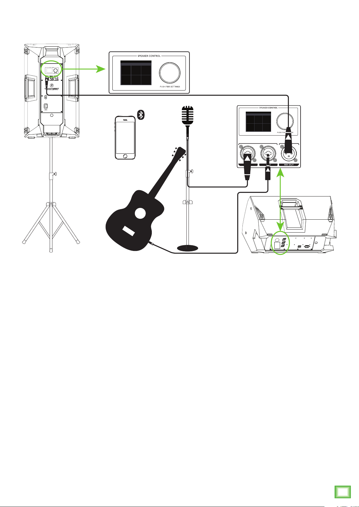
Thump loudspeakers are the perfect tool for singer-songwriters touring the local coffee shops.
Bring your favorite axe and mic, Thump loudspeakers and cables and power cords.
In this example, a dynamic microphone is connected to the channel 1 input of a Thump12BST
loudspeaker, used for monitoring purposes.
Now grab your axe and plug it directly into the channel 2 input. Or if you use effects, connect
the guitar to the effects input and another cable from the effects output to the channel 2 input.
Another Thump12BST loudspeaker will be used for the main PA. Simply connect a cable from
the Thump12BST monitor’s MIX OUT jack to the Thump12BST PA’s channel 1 input.
The last thing to connect is your device... via Bluetooth! With this, you can play backing tracks
and/or programmed drum beats to accompany your brilliant performance to the adoring crowd!
The bluetooth audio will stream to the monitor speaker and is linked to the main via the XLR connection.
Do not wirelessly link the loudspeakers or you will get redundant audio from the bluetooth source!
For the output, you will want to set a speaker mode, described in detail on page 14. For this type
of setup, Live works well for the main Thump12BST. However, don’t count out the Music mode!
Select the Monitor mode for the Thump12BST monitor.
Owner’s Manual
5
Page 6
Hookup Diagrams continued...
SPEAKER VOICING
MUSIC W/ SUBWOOFER
MUSIC LIVE SPEECH
+ +
MON
SUB SUB
LINE
HI-Z
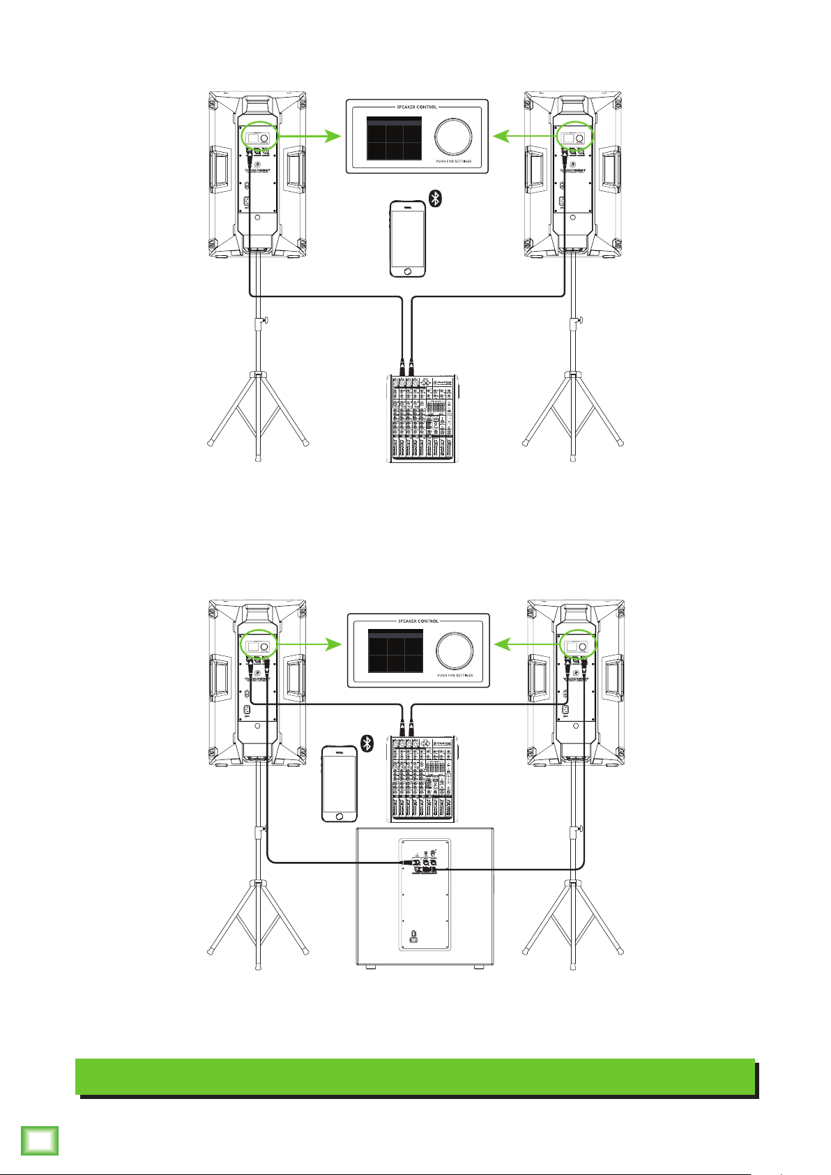
In this example, a ProFX8v2 mixer is connected directly to two Thump12BST loudspeakers.
It is the perfect setup for a small club or... a fun karaoke house party! Simply connect the L/R outputs
of the ProFX8v2 mixer to the CH1 input of each Thump12BST loudspeaker. For karaoke, you could
play tunes through the device (connected via Bluetooth) with mics plugged directly into the inputs
(or mixer first). Many options! Don’t forget to wirelessly link the speakers for stereo audio playback
from the device and set the Speaker Mode on both loudspeakers to Music!
SPEAKER VOICING
MUSIC W/ SUBWOOFER
MUSIC LIVE SPEECH
+ +
MON
SUB SUB
LINE
HI-Z
Thump12BST • Thump15BST Powered Loudspeakers
If you desire a little more boom, add a Thump18S subwoofer to the mix. Here, the L/R outputs
of a ProFX8v2 mixer are connected directly to the CH1 inputs of each Thump12BST loudspeaker.
Then the Mix Out of each loudspeaker is connected to the channel A and B inputs of a single
Thump18S subwoofer. Don’t forget to set the Speaker Modes to Music + Sub.
Small Club System
6
Thump12BST • Thump15BST Powered Loudspeakers
Page 7
Hookup Diagrams continued...
SPEAKER VOICING
MUSIC W/ SUBWOOFER
MUSIC LIVE SPEECH
+ +
SUB SUB
MON
Owner’s Manual
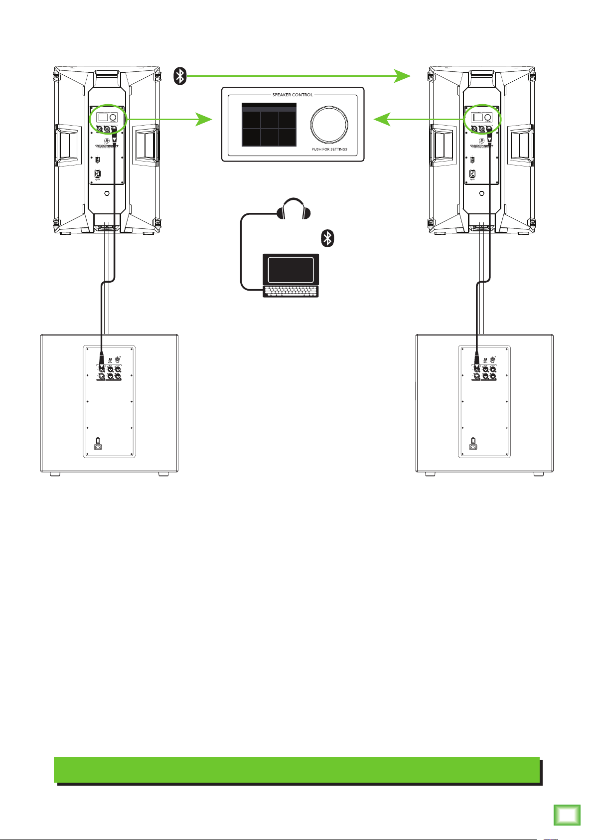
Perhaps you’re a DJ playing bumpin’ tunes in the middle of the night to a crowd that’s groovin’
and dancin’ to your fine selection.
In this example, a laptop is connected to the bluetooth channel of a Thump15BST loudspeaker which,
in turn, is linked to another Thump15BST loudspeaker.
The Mix Out of each loudspeaker is connected to the channel A input of each Thump18S subwoofer
and a set of headphones is connected to the phones jack of the laptop.
The Speaker Modes of both loudspeakers may be set to Music + Sub. Would you look at that!
Minimal cable spaghetti and up to 300 feet of bluetooth connectivity. A winning combination!
DJ System
Owner’s Manual
7
Page 8
Hookup Diagrams continued...
To next
Thump
loudspeaker
input
To next
Thump
loudspeaker
input
Main
Outs
1402VLZ4 Mixer
To next
Thump
loudspeaker
input
Thump12BST • Thump15BST Powered Loudspeakers
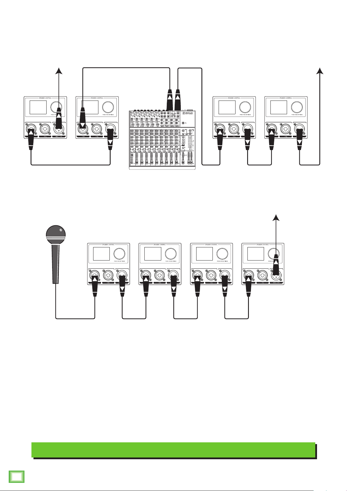
Thump loudspeakers may be daisy-chained via the male XLR connector labeled “MIX OUT”.
Simply plug the signal source (i.e., mixer output or microphone) into the input jack(s), and patch
that loudspeaker’s mix out jack to the next loudspeaker’s input jack, and so on, daisy-chaining
multiple Thump loudspeakers. See above for visual representations of daisy-chaining.
Daisy-Chaining Multiple Thump Loudspeakers
8
Thump12BST • Thump15BST Powered Loudspeakers
Page 9
Hookup Diagrams continued...
Owner’s Manual
SPEAKER VOICING
MUSIC W/ SUBWOOFER
MUSIC LIVE SPEECH
+ +
MON
SUB SUB
SPEAKER VOICING
MUSIC W/ SUBWOOFER
MUSIC LIVE SPEECH
+ +
MON
SUB SUB
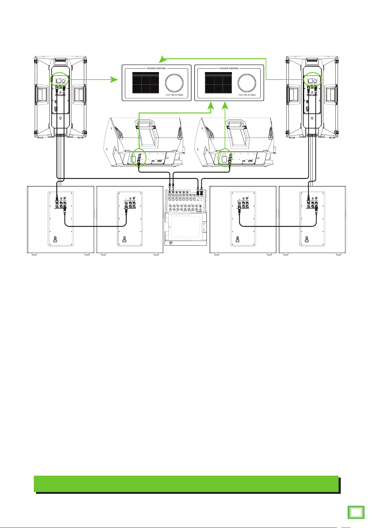
Here’s how to set up a large club system. In this example, the L/R outputs of a DL1608 mixer are
connected directly to the CH1 inputs of a pair of Thump15BST loudspeakers. The Speaker Modes
of these PA loudspeakers may be set to Music + Sub.
The Mix Out of each loudspeaker is then connected to the channel A input of a pair of Thump18S
subwoofers.From here, the channel A full range outputs of the two outer Thump18S subwoofers
are connected directly to the channel A inputs of another set of Thump18S subwoofers. Talk about
beefy low end!
The aux 1 and aux 2 sends from the mixer are connected directly to the CH1 inputs of a pair of
Thump12BST loudspeakers to be used as monitors for the band. The Speaker Modes of the monitor
loudspeakers may be set to Monitor.
There is no device shown in this hookup diagram, but it is entirely possible to connect one... after all,
there is still a Bluetooth channel! It would be good for playback music during band breaks and set
changeovers. The possibilities are endless!
Large Club System
Owner’s Manual
9
Page 10

Thump12BST / Thump15BST Loudspeakers: Rear Panel Features
2
2. Power Switch
Press the top of this rocker switch inwards to turn on
the loudspeaker. Press the bottom of this rocker switch
inwards to turn off the loudspeaker.
6
4
As a general guide, the mixer (or other
signal source) should be turned on first,
subwoofers next, and loudspeakers last.
As such, the loudspeakers should also be turned
off first, followed by the subwoofers, then the mixer.
This will reduce the possibility of any turn-on or
turn-off thumps and other noises generated by any
upstream equipment from coming out of the speakers.
3. XLR and 1/4" Combo Inputs
Both input channels may accept a balanced
mic signal using an XLR connector. They are wired
as follows, according to standards specified by the
AES (Audio Engineering Society).
XLR Balanced Wiring:
Pin 1 = Shield (ground)
Pin 2 = Positive (+ or hot)
Pin 3 = Negative (– or cold)
1
5
3
2
Thump Connect App
ThumpBST loudspeakers are designed to be used in
conjunction with the Thump Connect App. With it, all of
the hardware features listed here – and more! – may be
controlled remotely via Bluetooth connection. The only
thing the Thump Connect App can’t do is turn the unit
on and off.
More information about the Thump Connect App may
be found by visiting the Thump Connect App Reference
Guide.
Thump12BST • Thump15BST Powered Loudspeakers
1. Power Connection
This is a standard 3-prong IEC power connector.
Connect the detachable power cord (included in
the packaging with the loudspeaker) to the power
receptacle, and plug the other end of the power
cord into an AC outlet.
Make sure that the AC power is matched to
the AC power indicated on the rear panel
(below the IEC receptacle).
SHIELD
HOT
1
3
COLD
1
3
2
SHIELD
COLD
HOT
In addition to accepting a balanced mic signal using
an XLR connector, these input channels may also accept
1/4" line-level signals driven by balanced or unbalanced
sources.
Additionally, both input channels may accept Hi-Z
sources (such as guitars) via the 1/4" input without
the need for a separate DI box.
To connect balanced lines to these inputs, use
a 1/4" Tip-Ring-Sleeve (TRS) plug. “TRS” stands for
Tip-Ring-Sleeve, the three connection points available
on a stereo 1/4" or balanced phone jack or plug. TRS
jacks and plugs are used for balanced signals and are
wired as follows:
1/4" TRS Balanced Mono Wiring:
Sleeve = Shield
Tip = Hot (+)
Ring = Cold (–)
10
Disconnecting the plug’s ground pin is
dangerous. Don’t do it!
Thump12BST • Thump15BST Powered Loudspeakers
TIPSLEEVE
SLEEVERING
TIP
RING
RING
TIP
SLEEVE
Page 11

Thump12BST / Thump15BST Loudspeakers: Rear Panel Features continued...
SLEEVE
Owner’s Manual
To connect unbalanced lines to these inputs, use
a 1/4" mono (TS) phone plug, wired as follows:
1/4" TS Unbalanced Mono Wiring:
Sleeve = Shield
Tip = Hot (+)
SLEEVE
TIP
TIPSLEEVE
TIP
NEVER connect the output of an amplifier
directly to a Thump’s input jack. This could
damage the input circuitry!
4. Mix Out
This is a male XLR-type connector that produces
exactly the same signal that is connected to the input
jacks. Use it to daisy-chain several Thump loudspeakers
together off the same signal source(s).
5. LCD Display
This modern, high-resolution, all-color TFT LCD
Display is one of the most vital features of the
ThumpBST loudspeaker. It displays loudspeaker
information including (but not limited to) levels,
EQ, selected voicing, pairing the speakers and
a bluetooth device, settings, lock / unlock status
and other parameters. This is simply for for control
and monitoring locally at the loudspeaker.
The brightness is controllable, but an
overall screen brightness is required
for certain aspects of the set-up options.
1 2 BT Main
5 6
They are wired as follows, according to standards
specified by the AES (Audio Engineering Society):
Balanced XLR Output Connector
Pin 1 – Shield (ground)
Pin 2 – Positive (+ or hot)
Pin 3 – Negative (– or cold)
SHIELD
1
3
COLD
Balanced XLR Output Connector
2
HOT
1
3
2
SHIELD
COLD
HOT
See page 8 to learn more about daisy-chaining Thump
loudspeakers.
6. Speaker Control Knob
This push-button rotary encoder allows you to access
functions such as channel and master level control
and metering, application specific voicings & EQ,
wireless configuration, setup functions, product
information and much more! Details forthcoming...
The Bluetooth connection may disconnect
when affected by electrostatic discharge
(ESD) or electrical fast transients (EFT).
If this occurs, manually reconnect the
Bluetooth connection.
Owner’s Manual
11
Page 12

Speaker Control Functions
1 2 BT Main
CONFIG LOCK LCD
1 -5 MainBT
Mixer Screen
The following list provides the high level navigation
items, in order, on the user interface and their
subsequent user controlled parameters.
There are two screens to choose from as the default
with each containing an array of sub-menus:
Mixer – I/O metering, level control, channel
selection and control and more.
Levels
As seen in the first screen shot to the left, the mixer
screen is a representation of a mixer... a mixer on a
loudspeaker? What?! Yup!
Level Setup
Rotate the speaker control knob to scroll between
the selections. The current selection will illuminate in
a can’t-miss DayGlo green. In this example, channel 1
is selected. Once the parameter you want to change is
illuminated, press the knob to enter edit mode.
The top row selections change the levels of input
channels 1, 2 and BT and the Main output. Notice in the
screenshots below how each parameter illuminates as
the speaker control knob is rotated to the right from
channel 1 to 2, Bluetooth (BT) and the Main output
last.
1 2 BT Main 1 2 BT Main
EQ Menu
Menu – Provides icon selectors for all
user-controllable functions.
Mixer
MIXER
Mode
MODE BT
Thump12BST • Thump15BST Powered Loudspeakers
Config
Lock
1 2 BT Main 1 2 BT Main
BT
In order to change the level, push the speaker
control knob when the desired channel is illuminated.
In the same example, notice how the channel 2 fader
has been moved to the –5 dB mark. Once the level you
desire has been dialed in, press the speaker control
knob again to return to the mixer screen.
LCD
We will go through each, how to get there and how
to change settings.
After a selection is made, the LCD screen will revert
12
to your choice – either the Mixer or Menu screen – after
30 seconds of (speaker control) inactivity. You yourself
may continue to be as active (or inactive)as you want.
Rotate the speaker control knob to navigate between
the selections and push the button to open and edit the
parameters.
Thump12BST • Thump15BST Powered Loudspeakers
The level control ranges are as follows:
• Channels 1 and 2: –30 dB to +40 dB
• Bluetooth: –20 dB to 0 dB
• Main Output: –60 dB to +10 dB
All four may also be muted (via the
Thump Connect app). Red fader caps
indicate a muted channel, while white
fader caps indicate unmuted channels.
A muted channel will unmute once a level is changed
via the speaker control knob (or Thump Connect).
Page 13

EQ Setup | Access Menu
1 2 BT Main
Now, the bottom row also houses input channels 1, 2
and BT. But instead of raising or lowering levels, this is
where to adjust each channels’ EQ. Additonally, this is
where to access the Menu screen.
1 2 BT Main 1 2 BT Main
As seen below, we changed the channel 1 high,
mid and low EQ to +5 and the HPF setting to 110 Hz.
Press the speaker control knob to return to the previous
screen once the EQ settings you desire have been dialed
in.
1
High +5
1
High 0dB
Owner’s Manual
1 2 BT Main 1 2 BT Main
In order to change a channel’s EQ, push the speaker
control knob when the desired channel’s EQ icon is
illuminated.
Next, push the speaker control knob again once the
EQ you want to change is illuminated. See below.
Mid 0dB
Low 0dB
HPF 20Hz
1
High 0dB High 0dB
Mid 0dB
Low +5
HPF 20Hz
Mid +5
Low 0dB
HPF 20Hz
1
Mid 0dB
Low 0dB
HPF 110Hz
In addition to the four EQ choices shown above,
there’s a fifth and final selection: the left-facing arrow.
Illuminating and selecting this simply returns you
to the main mixer screen.
1
High 0dB
Mid 0dB
1
High 0dB
Mid 0dB
Low 0dB
HPF 20Hz
1
High 0dB
Mid 0dB
Low 0dB
HPF 20Hz
The EQ ranges are as follows:
• High: ±12 dB
• Mid: ±12 dB @ 2.5 kHz
• Low: ±12 dB @ 80 Hz
• HPF: 20 Hz – 400 Hz at 12 dB per octave
1
High 0dB
Mid 0dB
Low 0dB
HPF 20Hz
1
High 0dB
Mid 0dB
Low 0dB
HPF 20Hz
@ 6 kHz [Channels 1 and 2]
@ 12 kHz [Bluetooth]
[Channels 1 and 2 only]
Low 0dB
HPF 20Hz
Other than the aforementioned EQ settings screen,
this is also where to access the menu screen. From the
mixer screen, simply rotate the speaker control knob
right until the bottom right icon is illuminated (A).
Then push the knob to enter the menu screen (B).
MIXER
CONFIG LOCK LCD
MODE BT
(A) (B)
Let’s take a look and see what the menu screen does.
The first step is to flip the page!
Owner’s Manual
13
Page 14

Menu Screen
MIXER
CONFIG LOCK LCD
MODE BT MIXER
CONFIG LOCK LCD
MODE BT
MIXER
CONFIG LOCK LCD
MODE BT
SPEAKER VOICING
The menu screen displays six icons. Like the
mixer screen, just rotate the speaker control knob
until the icon of the parameter you want to change
is illuminated. Then push the knob to enter that icon’s
screen.
The six icon selectors are as follows:
• Mixer
• Speaker Mode
• Bluetooth
• Configuration
• Lock
• LCD
We’ll go through each one, starting with mixer
at the top left.
Speaker Mode
Speaker mode allows you to change the loudspeaker’s
speaker mode to tailor it to best suit your particular
application.
MIXER
CONFIG LOCK LCD
MODE BT
The six speaker modes are as follows:
• Music – This mode is full range, but focuses
on increased bass and brilliant high frequencies.
This is the place to start for most DJ / music
playback applications.
Mixer
This is the easiest to describe since we just went
through the mixer screen on the last two pages!
To recap, though, the mixer screen is where
to set levels and channel EQ.
MIXER
CONFIG LOCK LCD
MODE BT
Thump12BST • Thump15BST Powered Loudspeakers
• Live – This mode features a low frequency
roll-off to get rid of unwanted thumps and adds
boost and sparkle to mid-range and high frequencies.
This plug-and-play mode is perfect for singer-
songwriters.
• Speech – This mode features a significant low
frequency roll-off to get rid of unwanted thumps.
It also adds boost and sparkle to mid-range and high
frequencies, critical for speech applications.
This plug-and-play mode is perfect for larger venue
applications where speech is the primary audio
source in need of clear and precise intelligibility.
• Music + Sub – This
mode rolls off the low
end of the ThumpBST
loudspeaker to match
MUSIC W/ SUBWOOFER
MUSIC LIVE SPEECH
properly with the
Thump18S subwoofer.
+ +
SUB SUB
MON
• Live + Sub – This
mode rolls off the low end of the ThumpBST
loudspeaker to match properly with the Thump18S
subwoofer.
14
Thump12BST • Thump15BST Powered Loudspeakers
• Monitor – This mode features a low frequency
roll-off and a reduction around 2 kHz to ensure
maximum gain before feedback in monitor
applications.
As you had done previously, just rotate the speaker
control knob until the speaker mode you desire is
illuminated, then push to select it. As seen above,
we selected Music + Sub.
Refer to the Frequency Response graphs on page 27
for further information.
Page 15

Bluetooth
PAIRED
NOT PAIRED
CONNECT
PAIRED
DISCONNECT
NOT PAIRED
This is where to set up and view wireless connectivity
options for the devices and speakers.
Notice how the icon of the device also illuminates
Owner’s Manual
when paired.
MIXER
CONFIG LOCK LCD
MODE BT
Below is a list of the parameters that may be edited:
Device – The device may either be paired or not
paired.
To pair:
(1) Make sure “connect” is illuminated and push
the speaker control knob.
NOT PAIRED
CONNECT
NOT LINKED
CONNECT
BT MODE: ZONE
(2) The text “not paired” will change
to “discoverable...” and “connect” will change
to “cancel”. From here, you can either (A) turn
the device and device’s bluetooth on to pair,
or (B) push the speaker control knob to cancel
the action.
DISCOVERABLE...
CANCEL
The Bluetooth connection may disconnect
when affected by electrostatic discharge
(ESD) or electrical fast transients (EFT).
If this occurs, manually reconnect the
Bluetooth connection.
ThumpBST Loudpeaker – The loudspeaker may
either be linked or not linked. Additionally, this is
where to select the bluetooth mode [zone or stereo].
Lastly, if the bluetooth mode is stereo, you may select
which loudspeaker is located on the left and which
is on the right.
To link:
The steps to link speakers is quite similar to that
of pairing a device. (1) Make sure “connect” is
illuminated and push the speaker control knob.
CONNECT
NOT LINKED
CONNECT
BT MODE: ZONE
NOT LINKED
CONNECT
BT MODE: ZONE
(3) The text “discoverable...” will change to “paired”
and “cancel” will change to “disconnect”. From here,
you can either (A) use the device and Thump
Connect app to control the loudspeakers,
or (B) push the speaker control knob to disconnect.
DISCONNECT
NOT LINKED
CONNECT
BT MODE: ZONE
(2) The text “not linked” will change to “searching...”
and “connect” will change to “cancel”. From here,
you can either (A) turn the other ThumpBST on
and follow these same steps to link, or (B) push
the speaker control knob to cancel the action.
NOT PAIRED
CONNECT
SEARCHING...
CANCEL
BT MODE: ZONE
Owner’s Manual
15
Page 16

(3) The text “searching...” will change to “primary”
NOT PAIRED
NOT PAIRED
NOT PAIRED
CONNECT
NOT LINKED
CONNECT
BT MODE: ZONE
NOT PAIRED
CONNECT
PRIMARY
DISCONNECT
BT MODE: ZONE
NOT PAIRED
NOT PAIRED
NOT PAIRED
NOT PAIRED
on one loudspeaker and “secondary” on the other.
Also, “cancel” will change to “disconnect”.
From here, you can either (A) select a Bluetooth
mode (see below), or (B) push the speaker
control knob to disconnect.
CONNECT
PRIMARY
DISCONNECT
BT MODE: ZONE
CONNECT
SECONDARY
DISCONNECT
BT MODE: ZONE
Notice how the icon of the loudspeaker also
illuminates when linked.
BT Mode – This is where to select the bluetooth
mode [zone or stereo]. Rotate the speaker control
knob until BT mode is illuminated then push it to
enter and edit the BT mode.
CONNECT
STEREO: The stereo setting is your default two
loudspeaker setup, ideal for applications such
as a party, DJ, etc., where a device is paired
and streaming music in stereo. Here the main
level controls both speakers.
The following channels are available when
the Thump BSTs are linked in stereo:
• Ch. 1 Primary or Secondary
• Ch. 2 Primary or Secondary
• Bluetooth
• Stereo Main
If the bluetooth mode is set to stereo, you may select
which loudspeaker is located on the left and which
is on the right. Simply rotate the speaker control
knob so that channel is illuminated, then push
the button to enter and edit.
CONNECT
NOT LINKED
CONNECT
BT MODE: STEREO
CHANNEL:
LEFT
Rotate to illuminate your choice – left or right – then
push the button to select.
NOT LINKED
CONNECT
BT MODE: ZONE
From here, rotate the speaker control knob until
the bluetooth mode you prefer is illuminated: zone
or stereo. Then push to select.
Thump12BST • Thump15BST Powered Loudspeakers
NOT PAIRED
CONNECT
NOT LINKED
CONNECT
BT MODE: ZONE
NOT PAIRED
CONNECT
NOT LINKED
CONNECT
BT MODE: STEREO
CHANNEL: LEFT
Zone Stereo
So what’s the difference? Let’s take a look!
CONNECT
NOT LINKED
CONNECT
BT MODE: STEREO
CHANNEL:
LEFT
CONNECT
NOT LINKED
CONNECT
BT MODE: STEREO
CHANNEL:
Left Right
ZONE: The zone mode setting is your optional
loudspeaker setup, ideal for when the speakers
are placed in different locations and allows for
separate main level controls.
ThumpBST loudspeakers in zone mode
setting will receive a mono-summed signal.
The following channels are available when
the Thump BSTs are linked in zone mode:
• Ch. 1 Primary or Secondary
• Ch. 2 Primary or Secondary
• Bluetooth
• Primary or Secondary Main
RIGHT
16
Thump12BST • Thump15BST Powered Loudspeakers
As before, illuminating and selecting the left-facing
arrow returns you to the previous screen.
Page 17

Configuration
MIXER
CONFIG LOCK LCD
MODE BT MIXER
CONFIG LOCK LCD
MODE BT MIXER
CONFIG LOCK LCD
MODE BT
MIXER
CONFIG LOCK LCD
MODE BT MIXER
CONFIG LOCK LCD
MODE BT
CONFIG
CONFIG
CONFIG
CONFIG
CONFIG
CONFIG
CONFIG
CONFIG
ABOUT
This is where to configure each speaker’s LED status,
auto connect / link bluetooth and more.
Auto Link BT – Allows two previously paired
Owner’s Manual
speakers to automatically re-link if both are powered
on and in range. When illuminated, push the speaker
control knob to select between on or off.
MIXER
CONFIG LOCK LCD
MODE BT
This is similar to what you will see after first entering
the configuration screen.
Front LED:
Auto Pair BT:
Auto Link BT:
About
Restore
OFF
OFF
OFF
To change a setting, you will just need to rotate the
speaker control knob until the configuration you desire
to change is illuminated, then push to select it.
Front LED:
Auto Pair BT:
Auto Link BT:
About
Restore
OFF
OFF
ON
Front LED:
Auto Pair BT:
Auto Link BT:
About
Restore
On Off
About – Displays the current information about
your loudspeaker. There is really only one reason
to go here and that is if you’ve been directed so
by Technical Support.
Front LED:
Auto Pair BT:
Auto Link BT:
About
Restore
OFF
OFF
OFF
Firmware: v0.1.48
DSP: 15.3.03
BT: 1.14.54
ID: 00:12:6F:D6:85:0A
OFF
OFF
OFF
These are the choices from top to bottom:
Front LED – Decide if you want the front LED
on or off. When illuminated, push the speaker
control knob to select between on or off.
Front LED:
Auto Pair BT:
Auto Link BT:
About
Restore
ON
OFF
OFF
Front LED:
Auto Pair BT:
Auto Link BT:
About
Restore
On Off
Auto Pair BT – Allows a previously paired device
to auto reconnect if both the device and speaker
are powered on and in range. When illuminated,
push the speaker control knob to select between
on or off.
Restore – Restores all parameters back to their
default. This is a permanent reset with no undo,
so a confirmation dialog helps prevent accidents.
RESTORE
FACTORY
DEFAULTS?
OFF
OFF
OFF
YES NO
YES NO
Yes No
Illuminating and selecting the left-facing arrow
returns you to the previous screen.
RESTORE
FACTORY
DEFAULTS?
Front LED:
Auto Pair BT:
Auto Link BT:
About
Restore
OFF
ON
OFF
Front LED:
Auto Pair BT:
Auto Link BT:
About
Restore
On Off
OFF
OFF
OFF
Owner’s Manual
17
Page 18

Lock
CONFIG LOCK LCD
MODE BT MIXER
CONFIG LOCK LCD
MODE BT
MIXER
CONFIG LOCK LCD
MODE BT
CONTROL ACCESS
CONFIG LOCK LCD
MODE BT
LCD SETTINGS
LCD SETTINGS
LCD SETTINGS
LCD SETTINGS
LCD SETTINGS
LCD
This is where to lock and unlock the interface with
a secret 4-digit numeric password.
MIXER
CONFIG LOCK LCD
MODE BT
Locking – Push the speaker control knob to enter
lock mode. From here, rotate the speaker control
knob until the first number you desire is illuminated
and press to select. Follow the same procedure for
the next three numbers.
As seen below, we decided to go with 1-2-3-4 because
that’s (a “5” shy of) the same code that was used
on Spaceballs. Notice how “lock” appears and is
illuminated. Push the knob again to confirm the lock.
On the bottom-right is the LCD screen, where
you may change the settings for the screen saver
and (mixer and menu) home screen.
MIXER
CONFIG LOCK LCD
MODE BT
After pushing the speaker control knob on the LCD
screen, you will see something that looks like this:
Brightness:
Home Screen:
LOW
MIXER
32 4
1 213 4 5 6 7 8 9 0
DEL
No further changes may be made until the control
access is unlocked.
Unlocking – If you try to make any changes or select
anything, you will be routed directly to the lock
screen and the control access section. Here you
will need to re-enter the 4-digit code and push
Thump12BST • Thump15BST Powered Loudspeakers
the speaker control knob to unlock.
Secret Squirrel Unlock – If you – or worse, someone
else! – set up a 4-digit lock code and you don’t know
the passcode, there is a quick fix. Simply press and
hold down the speaker control knob down for a few
seconds and it will automatically unlock.
LOCK
The parameter on top is LCD brightness. Push the
speaker control knob again to edit the brightness.
There are three choices: low, high and off.
Brightness:
Home Screen:
LOW
MIXER
Brightness:
Home Screen:
HIGH
MIXER
Brightness:
Home Screen:
Low High Off
The brightness is controllable, but an
overall screen brightness is required
for certain aspects of the set-up options.
The next parameter that may be changed is the home
screen. Here there are two choices: mixer and menu.
Brightness:
Home Screen:
LOW
MIXER
OFF
MIXER
Del, of course, deletes the previous selected number
in case you made an oopsie. This is available whether
locking or unlocking.
Illuminating and selecting the left-facing arrow re-
18
turns you to the previous screen.
Thump12BST • Thump15BST Powered Loudspeakers
Page 19

Both screens were shown and described several pages
LCD SETTINGS
CONFIG LOCK LCD
LCD SETTINGS
1 2 BT Main
BBQ SETTINGS
BBQ SETTINGS
BBQ SETTINGS
ago, but they’re shown again below.
After pushing the speaker control knob on the BBQ
Owner’s Manual
screen, you will see something that looks like this:
Brightness:
Home Screen:
LOW
MIXER
Mixer
Brightness:
Home Screen:
LOW
MENU
MIXER
Menu
And, like before, illuminating and selecting the
left-facing arrow returns you to the previous screen.
MODE BT
Food:
Beverage:
Game: CROQUET
STEAK
BEER
The editable parameter on top is food. Push the
speaker control knob again to edit the food. There
are a variety of choices:
• Steak
• Burgers
• Hot Dogs
• Chicken / Wings
• Baby Back Ribs
• Fish
• Shish Kabobs
• Corn / Veggies
BBQ
Last, but not least... the BBQ screen! Who doesn’t like
to fire up the grill on a hot summer day, hang out with
friends and drink ice cold beverages... perfection, right?
Well, we agree, and decided to have a built-in BBQ right
in the ThumpBST Series. Genius!
Simply rotate the speaker control knob until the grill
is illuminated, then press to enter BBQ edit mode.
MIXER
CONFIG LOCK LCD
MODE BT NA
BBQ
The next parameter that may be changed is
the choice of frosty beverage. As with food, there
are multiple options:
• Beer
• Wine
• Mixed Drinks
• Lemonade / Iced Tea
• Soda
Food:
Beverage:
Games: CROQUET
• Water
• Coffee
The third – and final – parameter that may
be changed are the games. Again, many choices:
• Cornhole
• Croquet
• Horseshoes
• Ring Toss
• Beer Pong
Food:
Beverage:
Games: CROQUET
• Water Balloon Dodge Ball
• Wet T-shirt Contest
• Lawn Twister
• Sack Race
STEAK
BEER
STEAK
BEER
While a ThumpBST grille is one letter extra
that of grill – and may feasibly be used as a
grill – we don’t recommend using it as such.
As always, illuminating and selecting the
left-facing arrow returns you to the previous screen.
Owner’s Manual
19
Page 20

Protection Circuitry
AC Power
Thump loudspeakers employ a built-in limiter for
less distortion at peak levels. A dynamic bass response
circuit provides optimal low frequency response
regardless of overall output level. Additional protection
includes automatic thermal shutdown should the amp
overheat. However, with Class-D amp technology, which
is highly-efficient, this should never be a problem.
The protection circuits are designed to
protect the loudspeakers under reasonable
and sensible conditions. Should you choose
to ignore the warning signs [e.g. excessive distortion],
you can still damage the speaker in the loudspeaker
by overdriving it past the point of amplifier clipping.
Such damage is beyond the scope of the warranty.
Limiting
The driver has its own compression circuit which
helps protect it from damaging transient peaks.
The compressor is designed to be transparent and
is not noticeable under normal operating conditions.
Be sure the Thump loudspeaker is plugged into
an outlet that is able to supply the correct voltage
specified for your model. It will continue to operate
at lower voltages, but will not reach full power. Be sure
the electrical service can supply enough amperage for
all the components connected to it.
We recommend that a stiff (robust) supply of AC
power be used because the amplifiers place high
current demands on the AC line. The more power that
is available on the line, the louder the speakers will play
and the more peak output power will be available for
a cleaner, punchier bass. A suspected problem of “poor
bass performance” is often caused by a weak AC supply
to the amplifiers.
Never remove the ground pin on the power
cord or any other component of the Thump
loudspeaker. This is very dangerous.
Overexcursion Protection
A subsonic filter circuit just prior to the power
amplifier prevents ultra-low frequencies from being
amplified. Excessive low-frequency energy can damage
the woofer by causing it to “bottom out,” also know
as overexcursion, which is equivalent to a mechanical
form of clipping.
Thermal Protection
Thump12BST • Thump15BST Powered Loudspeakers
All amplifiers produce heat. Thump loudspeakers are
designed to be efficient both electrically and thermally.
In the unlikely event of the amplifier overheating, a
built-in thermal switch will activate, muting the signal.
When the amplifier has cooled down to a safe
operating temperature, the thermal switch resets
itself, and the Thump loudspeaker resumes normal
operation.
If the thermal switch activates, try turning down
the level control a notch or two on the mixing console
(or via the Speaker Control knob) to avoid overheating
the amplifier. Be aware that direct sunlight and/or
hot stage lights may be the culprit of an amplifier
overheating.
Care and Maintenance
Your Thump loudspeakers will provide many years of
reliable service if you follow these guidelines:
• Avoid exposing the loudspeakers to moisture.
If they are set up outdoors, be sure they are
under cover if rain is expected.
• Avoid exposure to extreme cold (below
freezing temperatures). If you must operate
the loudspeakers in a cold environment, warm
up the voice coils slowly by sending a low-level
signal through them for about 15 minutes prior
to high-power operation.
• Use a dry cloth to clean the cabinets. Only do
this when the power is turned off. Avoid getting
moisture into any of the openings of the
cabinet, particularly where the drivers are
located.
20
Thump12BST • Thump15BST Powered Loudspeakers
Page 21

Placement
Owner’s Manual
WARNING: Installation should only be done
by an experienced technician. Improper
installation may result in damage to the
equipment, injury or death. Make sure that the
loudspeaker is installed in a stable and secure way
in order to avoid any conditions that may be dangerous
for persons or structures.
Thump loudspeakers are designed to sit on the floor
or stage as the main PA or as monitors. They may also
be pole-mounted via the built-in socket on the bottom
of the cabinet. Be sure the pole is capable of supporting
the weight of the loudspeaker. The SPM200 is a great
option when using a subwoofer.
These loudspeakers may also be flown via their
integrated fly points as detailed on page 23. Be sure
to read the PA-A1 Eyebolt Installation Instructions,
as well.
NEVER attempt to suspend a Thump
loudspeaker by its handles.
When two cabinets are positioned side-by-side
such that the rear-angled faces of the enclosures
are parallel, the splay angle will be 90º. This matches
the 90˚ horizontal coverage pattern of each individual
loudspeaker; the interference between the two cabinets
will be minimized, but the total coverage of 180˚ may
be too wide for some applications. The mid and high
frequencies may also be reduced for those in the center
who are too close to the loudspeakers.
Reducing the splay angle will reduce the total
horizontal coverage, but it also creates an area both
speakers are covering. Instead of a nearfield hole, this
will cause comb-filtering effects in the frequency
response in the overlapping area. The smaller the splay
angle, the more energy will be delivered on-axis, but the
comb-filtering effects will get worse at the same time.
Top
Check to make sure that the support surface
(e.g. floor, etc.) has the necessary mechanical
characteristics to support the weight of the
loudspeaker(s).
When pole-mounting loudspeakers, be sure that they
are stabilized and secured from falling over or being
accidentally pushed over. Failure to follow these
precautions may result in damage to the equipment,
personal injury, or death.
As with any powered components, protect them from
moisture. Avoid installing the loudspeaker in places
exposed to harsh weather conditions. If you are setting
them up outdoors, make sure they are under cover if
you expect rain.
Thump loudspeakers are NOT designed to array
horizontally. If you feel you must put two speakers
side-by-side, you should have a good understanding
of the relationship between the splay angle (the angle
between the facing sides of the cabinets) and frequency
cancellation effects between cabinets.
0
90
900 Dispersion
up to 23 kHz
To reiterate, though, we strongly suggest
NOT arraying these loudspeakers horizontally.
Experimentation and experience will help you find
the right balance for your application.
Owner’s Manual
21
Page 22

Room Acoustics
Thump loudspeakers are designed to sound fantastic
in nearly every application.
But, room acoustics play a crucial role in the overall
performance of a sound system. However, the wide highfrequency dispersion of the Thump loudspeakers helps
to minimize the problems that typically arise.
Here are some additional placement tips to help
overcome some typical room problems that might arise:
• Placing loudspeakers in the corners of a room
increases the low frequency output and can
cause the sound to be muddy and indistinct.
• Placing loudspeakers against a wall increases
the low frequency output, though not as much
as corner placement. However, this is a good
way to reinforce the low frequencies, if so
desired.
• Avoid placing the speakers directly on a
hollow stage floor. A hollow stage can resonate
at certain frequencies, causing peaks and dips
in the frequency response of the room. It is
better to place them on a sturdy stand designed
to handle the weight of the loudspeaker.
• Highly reverberant rooms, like many
gymnasiums and auditoriums, are a
nightmare for sound system intelligibility.
Multiple reflections off the hard walls, ceiling,
and floor play havoc with the sound. Depending
on the situation, you may be able to take some
steps to minimize the reflections, such as
putting carpeting on the floors, closing
draperies to cover large glass windows, or
hanging tapestries or other materials on the
walls to absorb some of the sound.
However, in most cases, these remedies are not
possible or practical. So what do you do?
Making the sound system louder generally
doesn’t work because the reflections become
louder, too. The best approach is to provide as
much direct sound coverage to the audience
as possible. The farther away you are from
the speaker, the more prominent will be the
reflected sound.
Use more speakers strategically placed so they
are closer to the back of the audience. If the
distance between the front and back speakers
is more than about 100 feet, you should use a
delay processor to time-align the sound. (Since
sound travels about 1 foot per millisecond, it
takes about 1/10 of a second to travel 100 feet.)
Keep in mind that the speaker mode is a great way
to compensate for some of these issues. See page 14 for
more information.
Thump12BST • Thump15BST Powered Loudspeakers
• Position the loudspeakers so the highfrequency drivers are two to four feet above
ear level for the audience (making allowances
for an audience that may be standing/dancing
in the aisles). High frequencies are highly
directional and tend to be absorbed much
easier than lower frequencies. By providing
direct line-of-sight from the loudspeakers
to the audience, you increase the overall
brightness and intelligibility of the sound
system.
22
Thump12BST • Thump15BST Powered Loudspeakers
Page 23

Rigging
Owner’s Manual
Rigging Hardware and Accessories
WARNING: Installation should only be done
by an experienced technician. Improper
installation may result in damage to the
equipment, injury or death. Make sure that the
loudspeaker is installed in a stable and secure way
in order to avoid any conditions that may be dangerous
for persons or structures.
WARNING: The cabinet is suitable for rigging
via its fly points. NEVER attempt to suspend
a Thump loudspeaker by its handle.
Rigging Design Practices
Rigging a loudspeaker requires determining:
1. The rigging methods and hardware that meet
static, shock, dynamic, and any other load requirements
for supporting the loudspeaker from structure.
2. The design factor and required WLL (Working
Load Limit) for this support.
We strongly recommend the following rigging practices:
1. Documentation: Thoroughly document the design
with detailed drawings and parts lists.
Rigging our loudspeakers will invariably require
hardware not supplied by us. Various types of
load-rated hardware are available from a variety
of third-party sources. There are a number of such
companies specializing in manufacturing hardware
for designing and installing rigging systems. Each
one of these tasks is a discipline in its own right.
Because of the hazardous nature of rigging work
and the potential liability, engage companies that
specialize in these disciplines to do the work required.
We do offer certain accessory rigging items and some
of them may be used with a variety of products. While
these accessories are intended to facilitate installation,
the wide variety of possible installation conditions and
array configurations do not permit us to determine their
suitability or load rating for any particular application.
We are not in the business of providing complete
rigging systems, either as designers, manufacturers,
or installers. It is the responsibility of the installer to
provide a properly engineered, load-certified rigging
system for supporting the loudspeaker from structure.
Thump loudspeakers may be individually
flown using a PA-A1 Eyebolt Kit, part number
0031943.
2. Analysis: Have a qualified professional, such
as a licensed Professional Engineer, review and
approve the design before its implementation.
3. Installation: Have a qualified professional rigger
do the installation and inspection.
4. Safety: Use adequate safety precautions
and back-up systems.
Thump12BST / Thump15BST Fly Points
MP = Mounting Point
Rigging Notes
The Thump loudspeaker’s integral mounting
points are designed to support only the weight
of their own loudspeaker with suitable, external
hardware. This means that each Thump loudspeaker
must be supported independently of any other Thump
loudspeaker and any other loads. All rigging points
must be used to hang an Thump loudspeaker.
MP MP
Top Rear
MP
Owner’s Manual
23
Page 24

Appendix A: Service Information
Poor sound
• Is it loud and distorted? Make sure that you’re not
overdriving a stage in the signal chain. Verify that
all level controls are set properly.
If you think your Thump loudspeaker has a problem,
please check out the following troubleshooting tips and
do your best to confirm the problem. Visit the Support
section of our website (www.mackie.com/support)
where you will find lots of useful information such
as FAQs and other documentation. You may find the
answer to the problem without having to part with your
loudspeaker.
Troubleshooting
No power
• Our favorite question: Is it plugged in? Make sure
the AC outlet is live [check with a tester or lamp].
• Our next favorite question: Is the power switch
on? If not, try turning it on.
• Make sure the line cord is securely seated in the
line cord socket and plugged all the way into the
AC outlet.
• Is the power LED on the front panel illuminated?
If not, make sure the AC outlet is live. If so, refer
to “No sound” below.
• The internal AC line fuse may be blown. This is
not a user serviceable part. If you suspect the
AC line fuse is blown, please see the "Repair"
section next.
No sound
• Is the level knob for the input source turned all
the way down? Verify that all the volume controls
in the system are properly adjusted. Look at the
Thump12BST • Thump15BST Powered Loudspeakers
level meter to ensure that the mixer is receiving
a signal.
• Is the signal source working? Make sure the
connecting cables are in good repair and securely
connected at both ends. Make sure the output
level control on the mixing console is turned up
sufficiently to drive the inputs of the speaker.
• Make sure the mixer does not have a mute on or a
processor loop engaged. If you find something like
this, make sure the level is turned down before
disengaging the offending switch.
• Has it shut down? Make sure there is at least
six inches of free space behind each Thump
loudspeaker.
• Is the input connector plugged completely into
the jack? Be sure all connections are secure.
Noise
• Make sure all connections to the active
loudspeakers are good and sound.
• Make sure none of the signal cables are routed
near AC cables, power transformers, or other
EMI-inducing devices.
• Is there a light dimmer or other SCR-based
device on the same AC circuit as the Thump
loudspeaker? Use an AC line filter or plug the
loudspeaker into a different AC circuit.
Hum
• Try disconnecting the cable connected to the
input jack. If the noise disappears, it could be
a “ground loop,” rather than a problem with the
Thump loudspeaker. Try some of the following
troubleshooting ideas:
• Use balanced connections throughout your
system for the best noise rejection.
• Whenever possible, plug all the audio
equipment’s line cords into outlets which
share a common ground. The distance
between the outlets and the common ground
should be as short as possible.
Bluetooth Issues
• Please email or call Technical Support if you
are having Bluetooth connection issues:
o mackie.com/support-contact
o 1-800-898-3211
Repair
For warranty service, refer to the warranty
information on page 29.
Non-warranty service is available at a factoryauthorized service center. To locate the nearest
service center, visit www.mackie.com/support/servicelocator. Service for Thump loudspeakers living outside
the United States may be obtained through local dealers
or distributors.
If you do not have access to our website, please
call our Tech Support department at 1-800-898-3211
(normal business hours, Pacific Time), to explain the
problem. They will tell you where the nearest factoryauthorized service center is located in your area.
24
Thump12BST • Thump15BST Powered Loudspeakers
Page 25

Appendix B: Technical Information
Thump12BST / Thump15BST Loudspeakers Specifications
Owner’s Manual
Acoustic Performance
Frequency Range (–10 dB): 50 Hz – 23 kHz [Thump12BST]
32 Hz – 23 kHz [Thump15BST]
Frequency Range (–3 dB): 57 Hz – 20 kHz [Thump12BST]
39 Hz – 20 kHz [Thump15BST]
Horizontal Coverage Angle: 90º
Vertical Coverage Angle: 60º
Maximum SPL Peak: 126 dB [Thump12BST]
127 dB [Thump15BST]
Monitor Angle 45˚
Transducers
Low Frequency: 12 in / 305 mm [Thump12BST]
15 in / 381 mm [Thump15BST]
with ferrite
High Frequency: 1.4 in / 36 mm Titanium dome
compression driver
Power Amplifiers
System Power Amplification
Rated Power 1300 watts peak
Low Frequency Power Amplifier
Rated Power: 1000 watts peak
Rated THD < 1%
Cooling Convection
Design: Class D
High Frequency Power Amplifier
Rated Power: 300 watts peak
Rated THD < 1%
Cooling Convection
Design: Class AB
System Processing
Channel EQ 3-band, HPF
Main EQ 6 speaker modes
Loudspeaker Link Stereo / Zone [BT Mode]
LCD Settings Screen Saver / Home Screen
Equalization
Low ±12 dB @ 80 Hz
Mid ±12 dB @ 2.5 kHz
High ±12 dB @ 6 kHz [Ch. 1/2]
±12 dB @ 12 kHz [Bluetooth]
Increments ±1 dB
HPF 20 Hz – 400 Hz
@12 dB / octave [Ch. 1/2 only]
Input/Output
Input Type: 2x Female XLR Balanced
/ 1/4" Unbalanced
Mic-Line Impedance: 8 k balanced
1/4" TS, Wide-Z™ Impedance: 1 M unbalanced
Mix Out: Male XLR Balanced
Mix Out Impedance: 600 balanced
Main Control: Rotating knob
Electronic Crossover
Crossover Type: 24 dB/octave
Crossover Frequency: 2 kHz
Line Input Power
Detachable line cord 100 – 240 VAC, 50 – 60 Hz, 75W
AC Connector 3-pin IEC 250 VAC, 10 A male
Power Supply Type Switchmode
Safety Features
Input Protection Peak and RMS limiting,
power supply and amplifier
thermal protection
Display LEDs Defeatable front power,
Speaker Control
Status Info Input and output levels,
EQ speaker voicing
Bluetooth Information
Bluetooth Protocol 4.2
Bluetooth Function Audio Streaming and
User Interface Control
Bluetooth Class Class 1
Construction Features
Basic Design: Trapezoidal
Material: Polypropylene
Finish: Black, textured finish
Handles: One on each side,
one on top, one on bottom
Grille: Perforated metal with
weather-resistant coating
Display LEDs
Front: Power ON
Rear: Speaker Control
Operating Temperature: 0 – 40 ˚C
32 – 104 ˚F
Owner’s Manual
25
Page 26

Thump Loudspeaker Specifications continued...
Physical Properties
Thump12BST:
Height: 24.2 in / 615 mm
Width: 14.1 in / 358 mm
Depth: 14.0 in / 356 mm
Weight: 29.3 lb / 13.3 kg
Thump15BST:
Height: 27.0 in / 686 mm
Width: 17.4 in / 442 mm
Depth: 14.0 in / 356 mm
Weight: 35.1 lb / 15.9 kg
Mounting Methods:
Floor mount, pole mount via the built-in socket on the bottom
of the cabinet [Be sure the pole is capable of supporting the
weight of the Thump loudspeaker] or fly via three integrated
M10 mounting points (using M10 x 1.5 x 20 mm forged
shoulder eyebolts).
See page 23 for more information.
Thump12BST Loudspeaker Dimensions
Options
Thump12BST Speaker Bag P/N 2047360-09
Thump12BST Rolling Speaker Bag P/N 2047360-10
Thump15BST Speaker Bag P/N 2047360-11
Thump15BST Rolling Speaker Bag P/N 2047360-12
SPM200 Loudspeaker Pole Mount P/N 2035170-01
PA-A1 Forged Shoulder Eyebolt Kit
(3 x M10 x 1.5 x 20 mm) P/N 0031943
Disclaimer
Since we are always striving to make our products better by
incorporating new and improved materials, components, and
manufacturing methods, we reserve the right to change these
specifications at any time without notice.
The “Running Man” figure is a registered trademark of LOUD
Audio, LLC.
All other brand names mentioned are trademarks or registered
trademarks of their respective holders, and are hereby
acknowledged.
©2018 LOUD Audio, LLC.
All Rights Reserved.
WEIGHT
29.3 lb
13.3 kg
24.2 in
615 mm
Thump12BST • Thump15BST Powered Loudspeakers
Thump15BST Loudspeaker Dimensions
WEIGHT
35.1 lb
5.9 kg
27 in
686 mm
4. in
358 mm
4 in
356 mm
26
17.4 in
442 mm
Thump12BST • Thump15BST Powered Loudspeakers
14 in
356 mm
Page 27

Thump12BST and Thump15BST Loudspeaker Frequency Response Legend
100 dBSPL
Owner’s Manual
Music Speaker Mode – This mode is full range, but
focuses on increased bass and brilliant high frequencies.
This is the place to start for most DJ / music playback
applications.
Live Speaker Mode – This mode features a low
frequency roll-off to get rid of unwanted thumps
and adds boost and sparkle to mid-range and high
frequencies. This mode is perfect for plug-and-play
singer-songwriters.
Monitor Speaker Mode – This mode features a low
frequency roll-off and a reduction around 2 kHz
to ensure maximum gain before feedback in monitor
applications.
Thump12BST Loudspeaker Frequency Response
100 dBSPL
Music + Sub Speaker Mode – This mode rolls off
the low end of the ThumpBST loudspeaker to match
properly with the Thump18S subwoofer.
Live + Sub Speaker Mode – This mode rolls off
the low end of the ThumpBST loudspeaker to match
properly with the Thump18S subwoofer.
Speech Speaker Mode – This mode features
a significant low frequency roll-off to get rid of
unwanted thumps. It also adds boost and sparkle
to mid-range and high frequencies, critical for speech
applications. This plug-and-play mode is perfect for
larger venue applications where speech is the primary
audio source in need of clear and precise intelligibility.
90 dBSPL
80 dBSPL
20
100 1000 20000 10000
Frequency (Hz)
Thump15BST Loudspeaker Frequency Response
90 dBSPL
80 dBSPL
20
100 1000 20000 10000
Frequency (Hz)
Owner’s Manual
27
Page 28

Thump12BST / Thump15BST
Loudspeakers Block Diagram
HF
LF
HF
Amp
Mute
Limiter
Gain
Master
LF
Amp
Mute
Limiter
Thermal
Monitoring
Thump12BST • Thump15BST Powered Loudspeakers
Equalization
User
EQ
6 user
3x1 mixer
with user
Crossover
voicings
selectable
controlled
input gains
EQ
User
Equalization
EQ
User
28
Thump12BST • Thump15BST Powered Loudspeakers
Preamp
Digitally-
controlled
Preamp
Digitally-
controlled
Page 29

Limited Warranty
Please keep your sales receipt in a safe place.
This Limited Product Warranty (“Product Warranty”) is provided by LOUD Audio, LLC. (“LOUD”) and is applicable
to products purchased in the United States or Canada through a LOUD-authorized reseller or dealer. The Product Warranty
will not extend to anyone other than the original purchaser of the product (hereinafter, “Customer,” “you” or “your”).
For products purchased outside the U.S. or Canada, please visit www.mackie.com to find contact information for your local
distributor, and information on any warranty coverage provided by the distributor in your local market.
LOUD warrants to Customer that the product will be free from defects in materials and workmanship under normal use
during the Warranty Period. If the product fails to conform to the warranty then LOUD or its authorized service representative
will at its option, either repair or replace any such nonconforming product, provided that Customer gives notice of the
noncompliance within the Warranty Period to the Company at: www.mackie.com or by calling LOUD technical support
at 1.800.898.3211 (toll-free in the U.S. and Canada) during normal business hours Pacific Time, excluding weekends
or LOUD holidays. Please retain the original dated sales receipt as evidence of the date of purchase. You will need it
to obtain any warranty service.
For full terms and conditions, as well as the specific duration of the Warranty for this product, please visit www.mackie.com.
Owner’s Manual
The Product Warranty, together with your invoice or receipt, and the terms and conditions located at www.mackie.com
constitutes the entire agreement, and supersedes any and all prior agreements between LOUD and Customer related
to the subject matter hereof. No amendment, modification or waiver of any of the provisions of this Product Warranty
will be valid unless set forth in a written instrument signed by the party to be bound thereby.
Need help with the loudspeaker?
• Visit www.mackie.com/support to find: FAQs, manuals, addendums, and other documents.
• Email us at: www.mackie.com/support-contact
• Telephone 1-800-898-3211 to speak with one of our splendid technical support chaps
(Monday through Friday, normal business hours, Pacific Time).
Owner’s Manual
29
Page 30

16220 Wood-Red Road NE
Woodinville, WA 98072 • USA
Phone: 425.487.4333
Toll-free: 800.898.3211
Fax: 425.487.4337
www.mackie.com
 Loading...