

Page 1
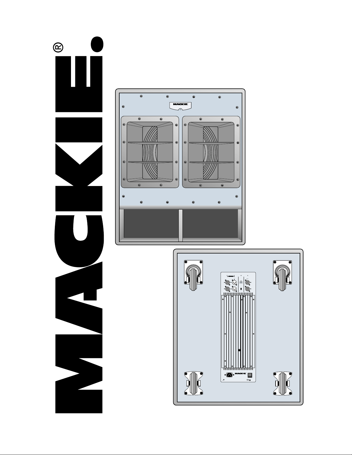
SWA1801
ACTIVE SUBWOOFER
SYSTEM USER’S MANUAL
ACTIV E
LIMIT SIGNAL THERMAL POWER
PARALLEL
SUBWOOFER
THRU
FULL RANGE
CONTROL
(FULL RANGE OUTPUT)
INPUT
NORMAL
L
SUBWOOFER
LEVEL
IN OUT
NORMAL
R
REV 180
PHASE
POWER
SWA1801
ACTIVE SUBWOOFER
115V-AC FUSE AC125V-T6.3A
DESIGNED BY MACKOIDS IN WOODINVILLE, WA, USA AND MACKIE EUROPE
COPYRIGHT ©2000 • THE FOLLOWING ARE TRADEMARKS OR REGISTERED
TRADEMARKS OF LOUD TECHNOLOGIES INC.: "MACKIE", AND THE "RUNNING MAN" FIGURE • PATENT PENDING
(MID/HIGH FREQ)
HIGH PASS
OUTPUT
120Hz
L
R
ON
Page 2
CAUTION AVIS
RISK OF ELECTRIC
RISQUE DE
CAUTION: TO REDUCE THE RISK OF ELECTRIC SHOCK
NO USER-SERVICEABLE PARTS INSIDE
REFER SERVICING TO QUALIFIED PERSONNEL
ATTENTION: POUR EVITER LES RISQUES DE CHOC
ELECTRIQUE, NE PAS ENLEVER LE COUVERCLE. AUCUN
ENTRETIEN DE PIECES INTERIEURES PAR L'USAGER. CONFIER
L'ENTRETIEN AU PERSONNEL QUALIFIE.
AVIS: POUR EVITER LES RISQUES D'INCENDIE OU
D'ELECTROCUTION, N'EXPOSEZ PAS CET ARTICLE
The lightning flash with arrowhead symbol within an equilateral
triangle is intended to alert the user to the presence of uninsulated
"dangerous voltage" within the product's enclosure that may be
of sufficient magnitude to constitute a risk of electric shock to persons.
Le symbole éclair avec point de flèche à l'intérieur d'un triangle
équilatéral est utilisé pour alerter l'utilisateur de la présence à
l'intérieur du coffret de "voltage dangereux" non isolé d'ampleur
suffisante pour constituer un risque d'éléctrocution.
The exclamation point within an equilateral triangle is intended to
alert the user of the presence of important operating and maintenance
(servicing) instructions in the literature accompanying the appliance.
Le point d'exclamation à l'intérieur d'un triangle équilatéral est
employé pour alerter les utilisateurs de la présence d'instructions
importantes pour le fonctionnement et l'entretien (service) dans le
livret d'instruction accompagnant l'appareil.
DO NOT OPEN
CHOC
NE PAS OUVRIR
DO NOT REMOVE COVER (OR BACK)
A LA PLUIE OU A L'HUMIDITE
SHOCK
ELECTRIQUE
SAFETY INSTRUCTIONS
1. Read Instructions — All the safety and operation in struc tions
should be read before this Mackie product is op er at ed.
2. Retain Instructions — The safety and operating in struc tions
should be kept for future reference.
3. Heed Warnings — All warnings on this Mackie product and in these
op er at ing in struc tions should be followed.
4. Follow Instructions — All op er at ing and other instructions should
be fol lowed.
5. Water and Moisture — This Mackie product should not be used
near water – for example, near a bathtub, washbowl, kitchen sink,
laundry tub, in a wet base ment, near a swimming pool, swamp or
salivating St. Bernard dog, etc.
6. Cleaning — Clean only with a dry cloth.
7. Ventilation — This Mackie product should be situated so that
its location or position does not interfere with its proper ventilation. For example, the Component should not be situated on a
bed, sofa, rug, or similar surface that may block any ventilation
openings, or placed in a built-in installation such as a bookcase
or cabinet that may impede the flow of air through ventilation
openings.
8. Heat — This Mackie product should be situated away from heat
sources such as radiators, or other de vic es which produce heat.
WARNING: The heat sink may reach high temperatures during
standard use. To ensure proper operation, allow a minimum of
six inches of clearance from the heat sink surface and adequate
ventilation.
9. Power Sources — This Mackie product should be con nect ed to
a power supply only of the type described in these op er a tion instructions or as marked on this Mackie product.
10. Power Cord Protection — Power supply cords should be routed
so that they are not likely to be walked upon or pinched by items
placed upon or against them, paying particular attention to cords at
plugs, convenience re cep ta cles, and the point where they exit this
Mackie product.
11. Object and Liquid Entry — Care should be taken so that objects
do not fall on, and liquids are not spilled into, this Mackie product.
12 . Damage Requiring Service — This Mackie product should be
serviced only by qualifi ed service per son nel when:
A. The power-supply cord or the plug has been damaged; or
B. Objects have fallen, or liquid has spilled into this Mackie
product; or
C. This Mackie product has been ex posed to rain; or
D. This Mackie product does not appear to operate normally or
exhibits a marked change in performance; or
E. This Mackie product has been dropped, or its chassis
damaged.
13 . Servicing — The user should not attempt to service this Mackie
product beyond those means de scribed in this operating manual. All
other servicing should be referred to the Mackie Service Department.
14. To prevent electric shock, do not use this polarized plug with an
extension cord, receptacle or other outlet unless the blades can be
fully inserted to prevent blade exposure.
Pour prévenir les chocs électriques ne pas utiliser cette fi che polariseé
avec un prolongateur, un prise de courant ou une autre sortie de
courant, sauf si les lames peuvent être insérées à fond sans laisser
aucune pariie à découvert.
15. Grounding or Po lar iza tion — Pre cau tions should be taken so
that the ground ing or po lar iza tion means of this Mackie product is
not defeated.
16. Power Precaution — Unplug this Mackie product during lightning storms or when unused for long periods of time. Note that this
Mackie product is not completely disconnected from the AC mains
service when the power switch is in the OFF position.
17. This apparatus does not exceed the Class A/Class B (whichever
is applicable) limits for radio noise emissions from digital apparatus as set
out in the radio interference regulations of the Canadian Department of
Com mu ni ca tions.
ATTENTION —Le présent appareil numérique n’émet pas de bruits
radioélectriques dépassant las limites applicables aux appareils
numériques de class A/de class B (selon le cas) prescrites dans le
règlement sur le brouillage radioélectrique édicté par les ministere
des communications du Canada.
WARNING — To reduce the risk of fi re or
electric shock, do not expose this ap pli ance to
rain or moisture.
WARNING — The cabinet has no rigging
points and is not suitable for fl ying. Never at-
tempt to suspend the cabinet by its handles.
2
Page 3
Lend Me Your Ears
Exposure to extremely
high noise levels may
cause permanent hear ing loss. In di vid u als vary
bil i ty to noise-in duced hearing loss, but nearly
everyone will lose some hearing if ex posed to
suffi ciently in tense noise for a pe ri od of time.
The U.S. Gov ern ment’s Oc cu pa tion al Safety and
Health Ad min is tra tion (OSHA) has spec i fi ed
the per mis si ble noise lev el exposures shown in
this chart.
considerably in sus cep ti -
Duration Per Day Sound Level dBA, Typical
In Hours
Slow Response Example
8 90 Duo in small club
6 92
4 95 Subway Train
3 97
2 100 Very loud classical music
1.5 102
1 105 Patrice screaming at Ron about dead lines
0.5 110
0.25 or less 115 Loudest parts at a rock con cert
According to OSHA, any exposure in excess
of these permissible limits could result in some
hearing loss. To ensure against potentially dangerous exposure to high sound-pressure levels,
it is recommend ed that all persons exposed to
equipment capable of producing these levels use
hearing protectors while this unit is in operation. Ear plugs or protectors in the ear canals or
over the ears must be worn when operating this
amplifi cation system in order to prevent a permanent hearing loss if exposure is in excess of
the limits set forth here.
CONTENTS
Lend Me Your Ears ...........................................................3
INTRODUCTION............................................................... 3
REAR PANEL DE SCRIP TION ........................................... 4
HOOKUP DIAGRAMS ...................................................... 5
CONNECTIONS................................................................ 6
PLACEMENT..................................................................... 6
AC POWER ......................................................................7
THERMAL CON SID ER ATIONS ........................................ 7
SERVICE IN FOR MA TION................................................. 7
Warranty Service ......................................................7
Troubleshooting ........................................................ 7
Repair ........................................................................ 9
SWA1801 SPEC I FI CA TIONS .........................................10
SWA1801 LIMITED WARRANTY ................................... 11
The SWA1801
can pro duce a
max i mum SPL of
135 dB @ 1m
INTRODUCTION
Thank you for choosing Mackie’s ac tive
sound reinforcement speaker sys tems.
The SWA1801 is a high-output active subwoofer system. It features a high-pre ci sion 18"
transducer combined with application-spe cifi c
amplifi er technology. The system is com posed of
a single, com pact subwoofer cab i net with built-in
control and am pli fi er elec tron ics.
Connecting and setting up the SWA1801 is
a breeze. It accepts a stereo or mono line-level
sig nal via fe male XLR input jacks. Male XLR
Thru jacks are provided for daisy-chain ing the
signal to ad di tion al SWA1801 cabinets. The
built-in cross over separates the low fre quen cies
from the high fre quen cies, and routes the high
fre quen cies to the male XLR high-pass output
jacks. Connect these to the in puts of full-range
active speak ers such as the Mackie SA1521s,
or to an amplifi er pow er ing a pair of pas sive
speak ers such as a combination of the Mackie
Don’t forget to visit our website at www.mackie.com
for more information about this and oth er Mackie products.
Part No. 0002871-90 Rev. B 8/05
©2004-2005 LOUD Technologies Inc. All Rights Reserved.
M•1400i and C300s. A Phase switch gives you the
option of reversing the po lar i ty of the sig nal to the
subwoofer by 180º. A Subwoofer Level con trol
al lows you to adjust the bal ance be tween the subwoofer and the full-range speak ers.
con tin u ous power. The amplifi er module sits on
a heatsink that elim i nat es the need for fans,
dra mat i cal ly ex tend ing life ex pect an cy, and elim i nat ing main te nance cycles. A tre men dous ben e fi t
of hav ing the amplifi er located with in the subwoofer
cab i net is that the SWA1801 func tions as a sys tem,
op ti miz ing acous tic, elec tron ic, and me chan i cal
de signs to achieve the high est level of per for mance
and val ue.
multi-layered birch plywood. Carrying han dles are
in te grat ed into each side for easy loading, and cast ers are attached to the rear for easy trans port.
The built-in amplifi er produces 800 watts of
The cabinet is constructed with 15 mm thick
3
R
Page 4
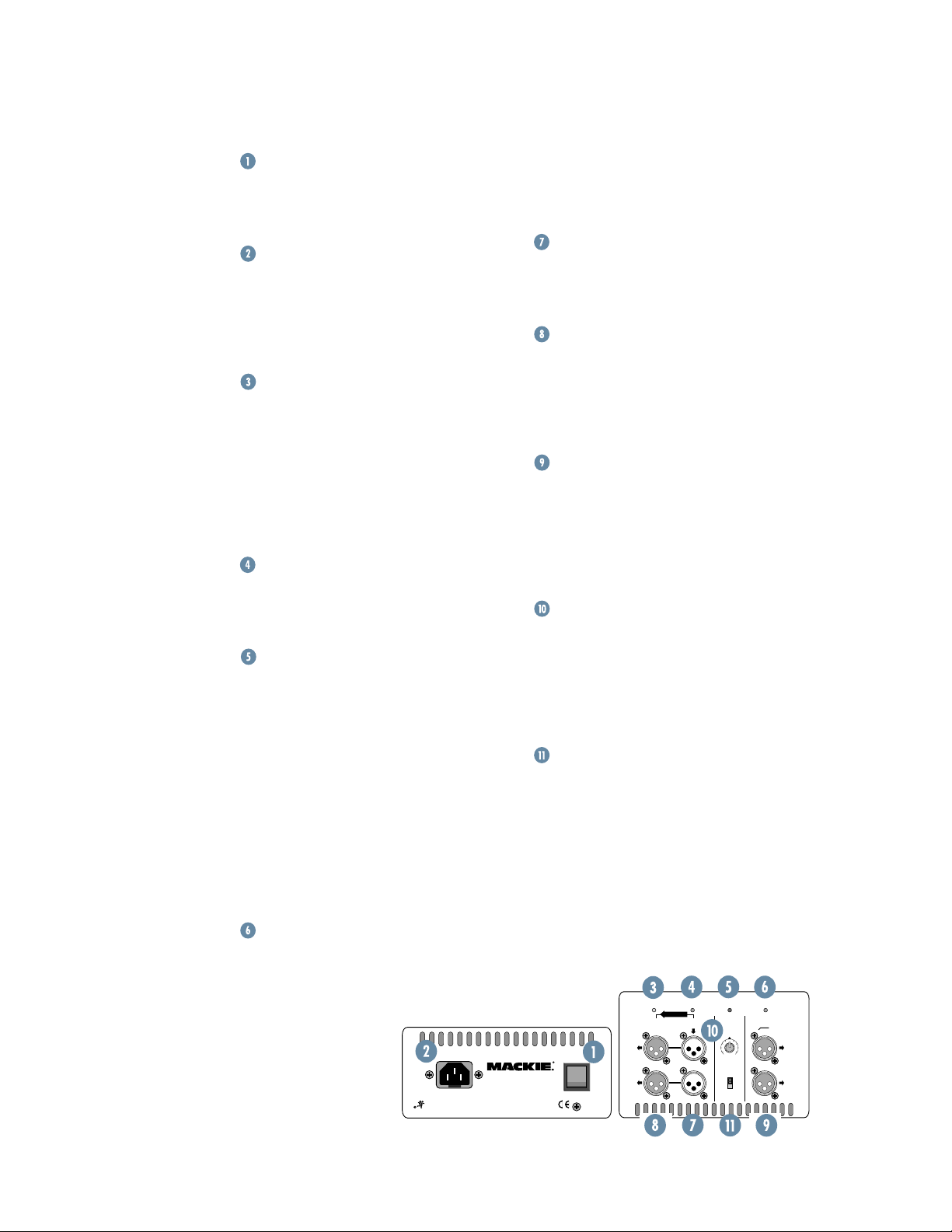
REAR PANEL DESCRIPTION
POWER Switch
Use this switch to turn the SWA1801 on
and off. Make sure the sig nal source’s lev el
con trol is turned down before you turn it on.
AC Receptacle
This is where you connect the AC line cord to provide AC power to the SWA1801’s
built-in power am pli fi ers. Plug the line cord
into an AC sock et prop er ly con fi g ured for
your par tic u lar model.
LIMIT Indicator
The SWA1801 has a built-in limiter that
pre vents the amplifi er outputs from over-
driving the transducers. The
LIMIT
in di ca tor
lights when the limiter is activated. It’s okay
for the
LIMIT
indicator to blink oc ca sion al ly,
but if it blinks fre quent ly or lights continuously, turn down the level con trol until the
LIMIT
indicator only blinks occasionally.
SIGNAL Present Indicator
This LED illuminates whenever there is
a signal present at the
FULL RANGE INPUT
con nec tor on the rear panel.
THERMAL Indicator
The SWA1801 has a thermal protection
circuit that monitors the internal tem per a ture of the amplifi ers and heatsink. If the
in ter nal temperature should exceed a safe
op er at ing level, this indicator lights and the
sig nal is mut ed to al low the amplifi er to cool.
When the tem per a ture cools to a safe level
once again, the ther mal protection cir cuit
de ac ti vates and normal operation resumes.
Note:
Activation of the thermal pro tec tion
circuit is an indication that you should take
steps to avoid continued ther mal prob lems.
See “Thermal Considerations” on page 7.
POWER Indicator
When the
and the linecord is connected to an active
POWER
switch is turned on
POWER
115V-AC FUSE AC125V-T6.3A
TRADEMARKS OF LOUD TECHNOLOGIES INC.: "MACKIE", AND THE "RUNNING MAN" FIGURE • PATENT PENDING
ACTIVE SUBWOOFER
DESIGNED BY MACKOIDS IN WOODINVILLE, WA, USA AND MACKIE EUROPE
COPYRIGHT ©2002 • THE FOLLOWING ARE TRADEMARKS OR REGISTERED
SWA1801
AC power supply, this indicator lights green
to let you know that you’re ready to rock
and roll. The cool blue LED on the front of
the cabinet works in the same way.
FULL RANGE INPUT
These are female XLR-type connectors
that accept a balanced line-level signal from
a mixing console or other signal source.
THRU (FULL RANGE OUTPUT)
These are male XLR-type connectors that
produce exactly the same signal that is con nect ed to the
FULL RANGE INPUT
jack. Use
it to dai sy-chain several SWA1801s to geth er
off the same sig nal source.
HIGH PASS (MID/HIGH FREQ) OUTPUT
These are male XLR-type connectors
that produce the frequencies above 120Hz.
Con nect these to a pair of full-range active
speak ers or to an amplifer/passive speaker
com bi na tion. The SWA1801 reproduces the
fre quen cies below 120Hz.
SUBWOOFER LEVEL Control
This adjusts the subwoofer level. The
cen ter detent position provides 15 dB of
head room with a nominal +4 dBu input
sig nal. Use this as a starting point for set ting
the balance between the subwoofer and the
main speakers.
PHASE
This switch reverses the polarity of the
subwoofer output. De pend ing on the place ment of the SWA1801 subwoofer relative to
the full-range speak ers, you may get a better
low-fre quen cy re sponse in the room if you
re verse the po lar i ty of the subwoofer’s sig nal.
Ex per i ment with this switch to de ter mine
which po si tion sounds best.
LIMIT SIGNAL THERMAL POWER
PARALLEL
FULL RANGE
THRU
(FULL RANGE OUTPUT)
ON
INPUT
IN OUT
L
R
SUBWOOFER
CONTROL
NORMAL
SUBWOOFER
LEVEL
NORMAL
REV 180
PHASE
HIGH PASS
(MID/HIGH FREQ)
OUTPUT
120Hz
L
R
4
Page 5

HOOKUP DIAGRAMS
Line-Level
Mid/High
Out Left
SA1521
Plays the Mid and
High Frequencies
Pol e
Mount
ACTIVE
SWA1801
Plays the Low
Frequencies
Pow e r
Cord
Pow e r
Cords
Full
Range
Left
Line-Level
Mid/High
Out Right
Range
1202-VLZPRO
Plays the Mid and
Mount
Full
Right
2 SWA1801S WITH 2 SA1521S
SA1521
High Frequencies
Pol e
ACTIVE
SWA1801
Plays the Low
Frequencies
Pow e r
Cord
Pow e r
Cords
C300
Plays the Mid and
High Frequencies
Pole
Mount
ACTIVE
SWA1801
Plays the Low
Frequencies
Pow e r
Cord
Amplifier
Line-Level
Hi-Pass Out
Full
Range
Stereo
Pow e r
1202-VLZPRO
Full
Range
C300
Plays the Mid and
High Frequencies
Pol e
Mount
ACTIVE
SWA1801
Plays the Low
Frequencies
Pow e r
Cord
2 SWA1801S WITH STEREO AMPLIFIER AND 2 C300S
SRM450
Plays the Mid and
High Frequencies
Full
Range
Pow e r
Line-Level
Hi-Pass
Out L
Cord
SWA1801
Plays the Low
Frequencies
1 SWA1801 WITH 2 SRM450S
SRM450
Plays the Mid and
High Frequencies
Full
Range
1202-VLZPRO
Pow e r
Line-Level
Pow e r
Cord
Hi-Pass
Out R
ACTIVE
Cord
C300
Plays the Mid and
High Frequencies
Plays the Low
SWA1801
Frequencies
Full
Range
Line-Level
Hi-Pass Out
Stereo Power
ACTIVE
Amplifier
1202-VLZPRO
Full
Range
Pow e r
Cord
Plays the Mid and
High Frequencies
Pow e r
Cord
C300
1 SWA1801 WITH STEREO AMPLIFIER AND 2 C300S
5
Page 6

CONNECTIONS
The SWA1801 has two female XLR in puts that accept a balanced line-level sig nal.
When con nect ing a bal anced sig nal, be sure
it’s wired per AES (Au dio En gi neer ing
So ci ety) standards:
XLR
Hot (+) Pin 2
Cold (–) Pin 3
Shield (Ground) Pin 1
The
THRU
output connectors allow you
to con nect more than one SWA1801 to your
sys tem. Sim ply plug the signal source (i.e.,
mixer output) into the fi rst speaker’s
RANGE IN PUT
er’s
THRU
jacks, and so on, dai sy-chain ing mul ti ple
speak ers.
The
FULL RANGE INPUT
elec tron ic cir cuit ry be tween — so the sig nal
com ing out of the
same as the sig nal go ing in.
The
a line-lev el signal of the fre quen cies above
120Hz that you connect to a pair of active
speak ers (or to a stereo am pli fi er pow er ing
a pair of pas sive speakers).
jacks, and patch that speak-
jacks to the next speak er’s
THRU
jack is wired straight from the
con nec tor — there is no
THRU
jack is ex act ly the
HIGH PASS OUTPUT
jacks pro vide
FULL
IN PUT
PLACEMENT
Balanced XLR Connectors
If connecting an unbalanced signal to the
SWA1801 balanced input, be sure that the
sig nal high (hot) connection is wired to Pin
2 and the unbalanced ground con nec tion
is wired to the low and the ground con nec tions of the balanced input (Pins 3 and
1). If there are ground-loop problems, try
con nect ing the unbalanced ground connection only to the input low connection (Pin
3), and leaving the input ground connection
dis con nect ed.
There are also four male XLR con nec tors
la beled
THRU (FULL RANGE OUTPUT)
HIGH PASS (MID/HIGH FREQ) OUT PUT
These are also wired ac cord ing to the
AES stan dard.
and
.
The SWA1801 subwoofer is de signed
to sit on the fl oor. A socket is provided
on the top of the SWA1801 for mounting
the Mackie SA1521 or SRM450 ac tive
speak ers. Use the op tion al Mackie speaker
mount ing pole (SPM100) to mount them
on the SWA1801 (see Hook up Di a gram on
page 5).
As with any powered
com po nents, pro tect the
SWA1801s from ex po sure
to mois ture. If you are
set ting them up out doors,
make sure they are under
cov er if you ex pect rain.
WA R N I N G : The cab i net
has no rigging points and
is not suit able for rig ging.
NEV ER at tempt to sus pend the SWA1801 by its
handles.
Unbalanced Male XLR Connector
6
Page 7

AC POWER
Be sure the SWA1801 is plugged into an
out let that is able to sup ply the cor rect volt age spec i fi ed for your mod el. If the volt age
should drop below 97% of the spec i fi ed line
volt age, the built-in am pli fi ers will no long er
be able to sup ply rat ed pow er. (They will
con tin ue to op er ate down to 80% of the rated line volt age, but won’t reach full pow er,
re sult ing in lower headroom.)
Be sure the elec tri cal ser vice can sup ply
enough am per age for all the com po nents
con nect ed to it.
We recommend that a stiff (robust)
sup ply of AC power be used be cause the
am pli fi ers place high current de mands on
the AC line. The more power that is avail able on the line, the louder the speakers
will play and the more peak out put power
will be avail able for clean er, punch i er bass.
A sus pect ed prob lem of “poor bass per for mance” is of ten caused by a weak AC
sup ply to the amplifi ers.
Never remove the ground
pin on the power cord
of the SWA1801 or any
other com po nent. This is
very dangerous.
THERMAL CONSIDERATIONS
The SWA1801 has a pow er ful 900 watt
am pli fi er built-in. As am pli fi ers produce
heat, it is im por tant to dis si pate the heat as
quick ly as possible. This re sults in in creased
re li abil i ty and lon gev i ty for the am pli fi er.
The amplifi er module is mounted on
a large heatsink, which is cooled by con vec tion where cool air is drawn through it’s
fi ns, car ry ing the heat away. In or der for
this con vec tion cooling to work ef fi cient ly,
it is important to pro vide ad e quate air space
be hind the loud speak er. When you position
the SWA1801, we rec om mend leav ing at
least six inch es of air space be hind it.
In the unlikely event of the amplifi er
over heat ing, a built-in thermal switch will
activate, which mutes the signal. When the
am pli fi er has cooled down to a safe op er -
at ing tem per a ture, the ther mal switch re sets
it self, and the SWA1801 re sumes nor mal
op er a tion.
If the thermal switch activates fre quent ly,
try turning down the level con trol a notch
or two on the mix ing console (or oth er
sig nal source) or on the subwoofer it self to
avoid over heat ing the am pli fi ers.
If the temperature in the room is too
high, it could cause the am pli fi er to over-
heat. In this case, you should try aim ing
a fan at the rear panel to move more air
across the heatsink panel.
SERVICE INFORMATION
Warranty Service
Details concerning warranty service are
spelled out on page 11 of this manual.
If you think your subwoofer has a
prob lem, please do ev ery thing you can
to con fi rm it before call ing for service,
in clud ing reading through the fol low ing
Trou ble shoot ing sec tion. Do ing so might
save you from being deprived of your Mack ie loudspeaker.
Of all Mackie prod ucts returned for
ser vice (which is hardly any at all), many
are coded “CND” — Could Not Dupli-
cate— which usually means the problem lay
some where else in the sys tem. The following trou ble shoot ing tips may sound obvious,
but here are some things you can check:
Troubleshooting
No power
• Our favorite question: Is it plugged in?
Make sure the AC outlet is live (check
with a tester or lamp).
• Our next favorite question: Is the
switch on? If not, try turning it on.
• Is the
• The internal AC line fuse may be blown.
POWER
glowing green? If not, make sure the AC
outlet is live. If so, re fer to “No sound”
next.
This is not a user serviceable part. If you
suspect the AC line fuse is blown, please
see the “Repair” section on page 9.
LED on the rear panel
POW ER
7
Page 8

No sound
• Is the input
source or the subwoofer turned all the
way down? Verify that all the vol ume
controls in the system are properly ad just ed.
• Is the signal source working (and making
union scale)? Make sure the con nect ing
cables are in good repair and se cure ly
connected at both ends. Make sure the
output volume (gain) control on the mixing console is turned up suf fi cient ly to
drive the inputs of the speaker.
• Make sure the mixer does not have a
Mute on or a Processor loop en gaged. If
you fi nd something like this, make sure
the volume/gain is turned down before
disengaging the offending switch.
• Is the thermal protection circuit ac ti vat ed?
Make sure there is at least six inches of
free space behind the SWA1801.
LEVEL
control for the input
Poor bass performance
• Check the polarity of the connections
between the mixer and the loud speak ers. You may have your positive
and negative connections re versed at
one end of one cable, causing one loud speak er to be out-of-phase.
• Try switching the
the rear panel. This affects the polarity
between the full-range speakers and the
SWA1801 and may improve the low-frequency response.
PHASE
switch on
Noise
• Make sure all connections to the active
loudspeakers are good and sound.
• Make sure none of the signal cables are
routed near AC cables, power trans form ers, or other EMI-inducing devices.
• Is there a light dimmer or other SCRbased device on the same AC cir cuit as
the SWA1801? Use an AC line fi lter or
plug the SWA1801 into a dif fer ent AC
circuit.
Hum
• Try dis con nect ing the cable connected
to the INPUT jack. If the noise dis ap pears, it could be a “ground loop,” rather
than a problem with the SWA1801. Try
some of the fol low ing trou ble shoot ing
ideas:
• Use balanced connections throughout
your system for the best noise rejection.
• Whenever possible, plug all the audio
equip ment’s linecords into outlets which
share a common ground. The dis tance
between the outlets and the common
ground should be as short as possible.
Poor sound
• Is it loud and distorted? Make sure that
you’re not overdriving a stage in the
signal chain. Verify that all level controls
are set properly.
• Is the input connector plugged
com plete ly into the jack? Be sure all con nec tions are secure. It’s a good idea to
periodically clean all electrical con nec tions with a non-lu bri cat ing electrical
contact cleaner.
8
Page 9

Repair
Service for Mackie products is available at
a factory-authorized service center. Service for Mackie products living outside the
United States can be obtained through local
dealers or distributors.
If your SWA1801 needs ser vice, please
fol low these in struc tions:
1. Review the preceding trou ble shoot ing
sug ges tions. Please.
2. Call Tech Support at 1-800-898-3211,
7am to 5pm PST, to explain the prob lem
in detail. They will ask you all sorts of
impertinent questions in the hope of
sorting out the problem. If it appears
that the SWA1801 needs repair, request
a Service Request Number. Have your
subwoofer’s serial number ready. Yo u
must have a Service Request Number
before you can obtain factory-au tho rized service.
3. Keep this user’s manual. We don’t need
it to repair the subwoofer.
4. Pack the subwoofer in its original
packaging, including protective wrap,
endcaps, and box. This is VERY IM-
PORTANT. When you call for the
Service Request Number, please let Tech
Support know if you need new pack ag ing. Mackie is not re spon si ble for any
damage that occurs due to non-factory
packaging.
5. Include a legible note stating your name,
shipping address (no P.O. boxes), daytime phone number, RA number, and
a detailed de scrip tion of the prob lem,
in clud ing how we can duplicate it.
6. Write the Service Request Number in
BIG PRINT
on top of the box.
7. Tech Support will tell you where to ship
the subwoofer for repair. We suggest
insurance for all forms of cartage.
8. You will need to contact the authorized
service center for their current turnaround times. The SWA1801 must be
packaged in its original packing box, and
must have the Service Request Number on the box. Once it is repaired, the
authorized service center will ship it
back by ground shipping, pre-paid (for
warranty repairs).
Note: Under the terms of the warranty,
you must ship or drop-off the unit to an
authorized service center. The return
ground shipment is covered for those
deemed by us to be under warranty.
Note: You must have a sales receipt from
an Authorized Mackie Dealer to qualify
for a warranty repair.
Need Help?
You can reach a technical support representative
Monday through Friday
from 7 AM to 5 PM PST at:
1-800-898-3211
After hours, visit www.mackie.com
or email us at: techmail@mackie.com
and click Support,
R
9
Page 10

SWA1801 SPECIFICATIONS
k
)
ACTIVE
System Specifi cations
Frequency Range (–10 dB)
35 Hz–120 Hz
Frequency Response (–3 dB)
45 Hz–120 Hz
Maximum SPL @ 1m 129 dB
Peak Output @ 1m 135 dB
Crossover Frequency 120 Hz (12 dB/octave)
Input Type Balanced differential
Input Impedance 50 kΩ
In put Protection Level protected
Thermal Protection Input stage muting,
auto-reset
Transducer Specifi cations
Low-Frequency Transducer
Diameter 18˝ (457 mm)
Voice Coil Diameter 4.0˝ (102 mm)
Power Amplifi er
Low-Frequency Power Amplifi er
*
Rated Power
800 Watts continuous
1000 Watts peak
Rated THD < 0.03%
Cooling Passive
Line Input Power
US 120 V, 60 Hz
Europe 230 V, 50 Hz
Enclosure Ge om e try
Rectangular
Mount ing Methods
Floor mount only
WARNING: The cab i net has no rigging points
and is not suit able for rig ging. NEV ER at tempt
to sus pend the SWA1801 by its handles.
Disclaimer
Since we are always striving to make our
products better by in cor po rat ing new and im proved
ma te ri als, com po nents, and man u fac tur ing methods,
we re serve the right to change these spec i fi ca tions at
any time with out no tice.
“Mackie” and the “Running Man” fi gure are
registered trade marks of LOUD Technologies Inc.
All other brand names men tioned are trade marks or registered trademarks of their respective
hold ers, and are hereby ac knowl edged.
©2004-2005 LOUD Technologies Inc.
All Rights Reserved.
Dimensions
23.5" (597 mm)
23.5" (597 mm)
11.2"
(284 mm)
3.5"
(89 mm)
* Rated power into loudspeaker’s rated impedance.
Physical Properties
Height 28.5˝ (724 mm)
Width 23.5˝ (597 mm)
FRONT SIDE
3.3"
(83 mm)
3.3"
(83 mm)
7.1"
(180 mm)
28.5" (724 mm)
9.4"
(239 mm)
5.2"
(132
mm)
3.5"
(89 mm)
Depth 23.5˝ (597 mm)
Weight 132 lbs. (60 kg)
Enclosure 15 mm thick multi-lay ered baltic
birch wood
23.5" (597 mm)
TOP
7.0"
(178
mm)
27.9" (709 mm)
SWA1801 On Axis Frequency Response
(with second and third harmonic components)
110
100
90
80
70
60
SPL, 100 dB @ 100 Hz
50
40
10
20 20
50 100 200 500 1k 2k 5k 10k
Frequency (Hz
Fundamental
Second
Third
Page 11

SWA1801 LIMITED WARRANTY
Please keep your sales re ceipt in a safe place.
A. LOUD Technologies Inc. warrants all materials,
work man ship and proper operation of this Mackie
SWA1801 for a period of fi ve years from the original
date of purchase, with the following exception: warranty on all its loud speak er com po nents including
woofers and compression drivers are only war rant ed for two years. If any defects are found in the
ma te ri als or work man ship or if the product fails to
function prop er ly during the applicable warranty
period, LOUD Technologies, at its option, will repair
or replace the product. This warranty applies only
to equip ment sold and delivered within the U.S.
by LOUD Tech nol o gies Inc. or its authorized
dealers.
B. Failure to register online or return the product
registration card will not void the fi ve-year warranty.
C. Service and repairs of Mackie products are to
be performed only at a factory-authorized facility (see D below). Unauthorized service, repairs,
or modifi cations will void this warranty. To obtain
repairs under warranty, you must have a copy of
your sales receipt from the authorized Mackie dealer
where you purchased the product. It is necessary to
establish the purchase date and determine whether
you Mackie product is within the warranty period.
D. To obtain factory-authorized service:
1. Call Mackie Technical Support at 800/898-
3211, 7 am to 5 pm Monday through Friday
(Pacifi c Time) to get a Service Request Number.
Products returned without a Service Request
Number will be refused.
2. Pack the product in its original shipping
carton. Also include a note explaining exactly
how to duplicate the problem, a copy of the sales
receipt with price and date showing, and your
return street address (no P.O. boxes or route
numbers, please!). If we cannot duplicate the
problem or establish the starting date of your
Limited Warranty, we may, at our option, charge
for service time.
3. Ship the product in its original shipping
carton, freight prepaid to the authorized service
center. The address of the closest authorized
service center will be given to you by Technical
Support.
IMPORTANT:
Number is plainly written on the shipping carton.
E. LOUD Technologies reserves the right to inspect
any products that may be the subject of any warranty
claims before repair or re place ment is carried out.
LOUD Technologies may, at our option, require proof
of the original date of purchase in the form of a dated
copy of the original dealer’s invoice or sales receipt.
Final determination of warranty coverage lies solely
with LOUD Technologies.
Make sure that the Service Request
F. Any products returned to one of LOUD Technolo-
gies factory-authorized service centers, and deemed
eligible for repair or re place ment under the terms
of this warranty, will be repaired or replaced within
thirty days of receipt by LOUD Technologies. LOUD
Technologies and its authorized service centers may
use refurbished parts for repair or replacement of
any product. Products returned to LOUD Tech nol o gies that do not meet the terms of this Warranty will
not be repaired unless payment is received for labor,
ma te ri als, return freight, and in sur ance. Prod ucts
repaired under warranty will be returned freight prepaid by LOUD Technologies to any location within
the bound aries of the USA.
G. LOUD Technologies warrants all repairs per formed on Mackie products for 90 days or for the
re main der of the original warranty period. This
warranty does not extend to damage resulting from
improper installation, misuse, neglect or abuse, or
to exterior appearance. This warranty is recognized
only if the inspection seals and serial number on the
unit have not been defaced or removed.
H. LOUD Technologies assumes no re spon si bil i ty for
the quality or time li ness of repairs performed by an
authorized service center.
I. This warranty is extended to the original pur chas er and to anyone who may subsequently
pur chase this product within the applicable warranty period. A copy of the original sales receipt is
required to obtain warranty service.
J. This is your sole warranty. LOUD Technologies
does not authorize any third party, including any
dealer or sales rep re sen ta tive, to assume any liability
on behalf of LOUD Technologies or to make any warranty for LOUD Technologies.
K. THE WARRANTY GIVEN ON THIS PAGE IS THE
SOLE WARRANTY GIVEN BY LOUD TECH NOL O GIES
INC. AND IS IN LIEU OF ALL OTHER WAR RAN TIES,
EXPRESS AND IMPLIED, IN CLUD ING THE WARRANTIES OF MERCHANTABILITY AND FITNESS
FOR A PARTICULAR PURPOSE. THE WARRANTY
GIVEN ON THIS PAGE SHALL BE STRICTLY
LIM IT ED IN DURATION TO FIVE YEARS FROM
THE DATE OF ORIG I NAL PUR CHASE FROM
AN AU THO RIZED MACKIE DEAL ER. UPON
EX PI RA TION OF THE AP PLI CA BLE WARRANTY PERIOD, LOUD TECH NOL O GIES INC. SHALL HAVE
NO FURTHER WARRANTY OB LI GA TION OF ANY
KIND. LOUD TECH NOL O GIES INC. SHALL NOT
BE LIABLE FOR ANY INCIDENTAL, SPECIAL, OR
CON SE QUEN TIAL DAMAGES THAT MAY RESULT
FROM ANY DEFECT IN THE MACKIE PRODUCT
OR ANY WARRANTY CLAIM. Some states do not
allow exclusion or lim i ta tion of incidental, special,
or con se quen tial damages or a lim i ta tion on how
long warranties last, so some of the above lim i ta tions
and exclusions may not apply to you. This warranty
pro vides specifi c legal rights and you may have other
rights which vary from state to state.
11
Page 12

16220 Wood-Red Road NE • Woodinville, WA 98072 • USA
United States and Canada: 800.898.3211
Europe, Asia, Central and South America: 425.487.4333
Middle East and Africa: 31.20.654.4000
Fax: 425.487.4337 • www.mackie.com
E-mail: sales@mackie.com
 Loading...