

Mackie SRM350 User Manual

SRM350
v2 Active
Sound ReinfoRceMent
SPeAKeR uSeR’S MAnuAl
2
IMPORTANT SAFETY INSTRUCTIONS
PORTABLE CART WARNING
Carts and stands - The
Component should be used
only with a cart or stand
that is recommended by
the manufacturer.
A Component and cart
combination should be
moved with care. Quick
stops, excessive force, and
uneven surfaces may cause
the Component and cart
combination to overturn.
CAUTION AVIS
RISK OF ELECTRIC SHOCK
DO NOT OPEN
RISQUE DE CHOC ELECTRIQUE
NE PAS OUVRIR
CAUTION: TO REDUCE THE RISK OF ELECTRIC SHOCK
DO NOT REMOVE COVER (OR BACK)
NO USER-SERVICEABLE PARTS INSIDE
REFER SERVICING TO QUALIFIED PERSONNEL
ATTENTION: POUR EVITER LES RISQUES DE CHOC
ELECTRIQUE, NE PAS ENLEVER LE COUVERCLE. AUCUN
ENTRETIEN DE PIECES INTERIEURES PAR L'USAGER. CONFIER
L'ENTRETIEN AU PERSONNEL QUALIFIE.
AVIS: POUR EVITER LES RISQUES D'INCENDIE OU
D'ELECTROCUTION, N'EXPOSEZ PAS CET ARTICLE
A LA PLUIE OU A L'HUMIDITE
The lightning flash with arrowhead symbol within an equilateral
triangle is intended to alert the user to the presence of uninsulated
"dangerous voltage" within the product's enclosure that may be
of sufficient magnitude to constitute a risk of electric shock to persons.
Le symbole éclair avec point de flèche à l'intérieur d'un triangle
équilatéral est utilisé pour alerter l'utilisateur de la présence à
l'intérieur du coffret de "voltage dangereux" non isolé d'ampleur
suffisante pour constituer un risque d'éléctrocution.
The exclamation point within an equilateral triangle is intended to
alert the user of the presence of important operating and maintenance
(servicing) instructions in the literature accompanying the appliance.
Le point d'exclamation à l'intérieur d'un triangle équilatéral est
employé pour alerter les utilisateurs de la présence d'instructions
importantes pour le fonctionnement et l'entretien (service) dans le
livret d'instruction accompagnant l'appareil.
1. Read these instructions.
2. Keep these instructions.
3. Heed all warnings.
4. Follow all instructions.
5. Do not use this apparatus near water.
6. Clean only with dry cloth.
7. Do not block any ventilation openings. Install in accordance with the
manufacturer’s instructions.
8. Do not install near any heat sources such as radiators, heat registers,
stoves, or other apparatus (including amplifiers) that produce heat.
9. Do not defeat the safety purpose of the polarized or grounding-type
plug. A polarized plug has two blades with one wider than the other.
A grounding-type plug has two blades and a third grounding prong.
The wide blade or the third prong are provided for your safety. If the
provided plug does not fit into your outlet, consult an electrician for
replacement of the obsolete outlet.
10. Protect the power cord from being walked on or pinched particularly
at plugs, convenience receptacles, and the point where they exit
from the apparatus.
11. Only use attachments/accessories specified by the manufacturer.
12. Use only with a cart, stand, tripod, bracket, or table specified by the
manufacturer, or sold with the apparatus. When a cart is used, use
caution when moving the cart/apparatus combination to avoid injury
from tip-over.
13. Unplug this apparatus during lightning storms or when unused for
long periods of time.
14. Refer all servicing to qualified service personnel. Servicing is required
when the apparatus has been damaged in any way, such as powersupply cord or plug is damaged, liquid has been spilled or objects
have fallen into the apparatus, the apparatus has been exposed to
rain or moisture, does not operate normally, or has been dropped.
15.
This apparatus shall not be exposed to dripping or splashing, and no object filled with liquids, such as vases, shall be placed on the apparatus.
16. This apparatus has been designed with Class-I construction and must
be connected to a mains socket outlet with a protective earthing
connection (the third grounding prong).
17.
This apparatus has a detachable power cord that is connected to the IEC
socket on the rear panel and should remain readily accessible to the user.
18. This apparatus has been equipped with an all-pole, rocker-style AC
mains power switch. This switch is located on the rear panel and
should remain readily accessible to the user.
19. This apparatus does not exceed the Class A/Class B (whichever is ap-
plicable) limits for radio noise emissions from digital apparatus as set
out in the radio interference regulations of the Canadian Department
of Communications.
ATTENTION —
Le présent appareil numérique n’émet pas de bruits
radioélectriques dépassant las limites applicables aux appareils numériques de
class A/de class B (selon le cas) prescrites dans le réglement sur le brouillage
radioélectrique édicté par les ministere des communications du Canada.
20. Exposure to extremely high noise levels may cause permanent
hearing loss. Individuals vary considerably in susceptibility to noiseinduced hearing loss, but nearly everyone will lose some hearing if
exposed to sufficiently intense noise for a period of time. The U.S.
Government’s Occupational Safety and Health Administration (OSHA)
has specified the permissible noise level exposures shown in the
following chart.
According to OSHA, any exposure in excess of these permissible limits
could result in some hearing loss. To ensure against potentially danger
ous exposure to high sound pressure levels, it is recommended that all
persons exposed to equipment capable of producing high sound pres
sure levels use hearing protectors while the equipment is in operation.
Ear plugs or protectors in the ear canals or over the ears must be worn
when operating the equipment in order to prevent permanent hearing
loss if exposure is in excess of the limits set forth
Duration Per Day Sound Level dBA, Typical
In Hours Slow Response Example
8 90 Duoinsmallclub
6 92
4 95 SubwayTrain
3 97
2 100 Veryloudclassicalmusic
1.5 102
1 105 TamiscreamingatAdrianaboutdeadlines
0.5 110
0.25orless 115 Loudestpartsatarockconcert
here.
WARNING — To reduce the risk of fire
or electric shock, do not expose this
apparatus to rain or moisture.
-
-

R
Contents
IMPORTANT SAFETY INSTRUCTIONS .......................................2
INTRODUCTION .......................................................................4
The Transducers ...............................................................4
Power Amplifiers ............................................................4
The Crossover ..................................................................4
The Cabinet .....................................................................4
HOOKUP DIAGRAMS ..............................................................6
Quick Start ......................................................................6
REAR PANEL DESCRIPTION ......................................................8
1. IEC Socket ....................................................................8
2. POWER Switch ............................................................8
3. POWER Indicator .........................................................8
4. CONTOUR ...................................................................8
5. LEVEL ...........................................................................8
6. MIC/LINE Switch ..........................................................9
7. SIGNAL Indicator .........................................................9
8. LIMIT Indicator .............................................................9
9. INPUT Connector .........................................................9
10. THRU Connector ........................................................9
CONNECTIONS ......................................................................10
PLACEMENT ...........................................................................10
Room Acoustics .............................................................10
RIGGING ..............................................................................
THERMAL CONSIDERATIONS .................................................12
AC POWER CONSIDERATIONS ..............................................12
AC Power Distribution ...................................................12
SERVICE INFORMATION ........................................................14
Troubleshooting .............................................................14
Repair ............................................................................16
CARE AND MAINTENANCE ....................................................16
SRM350 v2 SPECIFICATIONS .................................................17
SRM350 v2 BLOCK DIAGRAM...............................................18
SRM350 v2 LIMITED WARRANTY ..........................................19
11
• Please write the serial number for your SRM350 v2 here
(or for both SRM350 v2s if you have two) for future reference
(i.e., insurance claims, tech support, return authorization, etc.):
Loudspeaker 1 Loudspeaker 2
Purchased at:___________________________________ Date of Purchase:_____________
Don’t forget to visit our website at www.mackie.com
for more information about this and other Mackie products.
Part No. 0026949 Rev. A 11/07
©2003-2007 LOUD Technologies Inc. All Rights Reserved.
3

4
INTRODUCTION
Thank you for choosing LOUD Technologies’ Mackie ac-
tive sound reinforcement speakers.
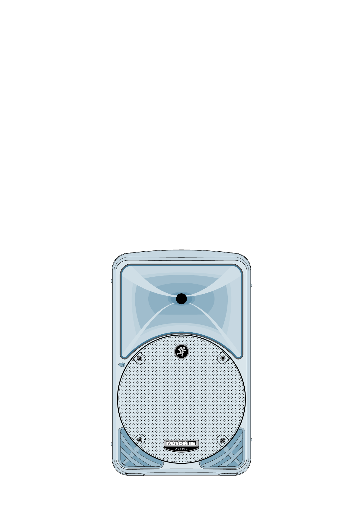
The SRM350 v2 is a redesigned version of our popular
SRM350 active loudspeaker. With its newly designed Class-D
Fast-Recovery amplifiers, high-output compression
and new 10" neodymium woofer, it produces an even
smoother sound than the original. SRM means Sound Reinforcement Monitor, and the SRM350 v2 truly produces a
studio quality sound in a sound reinforcement speaker.
Our design goal was to build a sound reinforcement
speaker with:
1. High precision, high output, and accurate playback.
Very wide, smooth dispersion of mid and high frequencies.
2.
3. Ergonomically correct physical design for easy transport
and set up.
Through the combined resources of our top-notch
mechanical and analog engineers, and our experienced
transducer engineers at EAW, we were able to achieve our
design goals in every aspect. The result is a sound reinforcement system equally at home in a concert setting, in the
studio, impromptu concerts on the studio roof, in the cinema,
or in a home theater.
driver
The Transducers
The SRM350 v2 active speakers feature a 10-inch highpower low-frequency woofer with a neodymium magnet,
and a 1.4-inch titanium diaphragm
compression driver. This high-fre
on an acoustically non-resonant exponential waveguide,
providing a wide, controlled dispersion and precise
reproduction of the critical upper mid-range and high
frequencies. The result is an unbelievably smooth off-axis
response that allows everyone
ence the same high-resolution audio no matter where they
are seated.
high-output ceramic
quency driver is mounted
in the audience to experi-
Power Amplifiers
To power these beauties, each SRM350 v2 includes two
of our acclaimed FR Series “Fast Recovery” power amplifiers. In addition, the low-frequency amplifier uses a Class-D
design for improved efficiency and cleaner power. Our
exclusive designs use low negative feedback, yet allow the
amplifiers to maintain low distortion and stability and to
quickly recover when driven into clipping.
The amplifiers include the following features:
• The low-frequency amplifier produces 165 continuous
watts before clipping.
• The high-frequency amplifier produces 30 continuous
watts before clipping.
• When the output from either amplifier begins to clip,
a limiter gently reduces the input signal level until the
output is no longer clipping.
• The low-frequency amplifier also has a Dynamic Bass
Boost circuit. Our ears are more sensitive to bass frequencies at high volume levels than at softer volumes.
This unique circuit automatically reduces the low
frequencies below 70 Hz as the volume of the speakers goes up. This results in improved efficiency for the
low-frequency amplifier because it is not wasting power
trying to reproduce frequencies we hear better at loud
volumes. Instead, the power is used for the frequencies
where it is needed, resulting in a louder sound.
Warning: Although the amplifiers have
these protection circuits, you must
still make sure the LIMIT light is not
blinking continuously. If it is, turn
down your mixer faders, or preamplifier gain, or turn down the SRM350 v2
LEVEL control.
The Crossover
The built-in electronic crossover is a 24 dB/octave
Linkwitz-Riley design. Although more expensive than other
crossover designs, the benefits provided by the LinkwitzRiley design have been well documented. These benefits
include:
• Absolutely flat frequency response throughout the
bandpass, without the characteristic ripple near the
crossover point exhibited by other designs.
• The sharp 24 dB per octave roll-off of the filters ensures
that the transducers aren’t reproducing frequencies
outside of their capabilities.
• The acoustic sum of the two driver responses is unity
at the crossover frequency, resulting in perfect power
response.
• Our heroic engineers have worked carefully to en
sure that the SRM350 v2 also provides perfect phase
response. This diligence has yielded phenomenal accuracy, even if you are standing 20 feet away.
-
The Cabinet
The SRM350 v2 cabinet was designed to be the strongest
molded composite cabinet on the planet. This material is as
strong as concrete, and rigid enough to prevent unwanted
vibrations in the cabinet. An optional bracket kit is available for the top and bottom of the cabinet to be used for
flying, and a socket is provided in the bottom of the cabinet
for mounting on a tripod stand. Although it is an exceptional choice for installed sound situations, its light weight and
durable finish also make it ideal for portable sound system
use. The asymmetrical trapezoidal design of the cabinet
makes it easy to use as a floor wedge for stage monitor applications.
The Active Advantage
There are a number of advantages to using an active
speaker system over a passive loudspeaker:
• The internal crossover is active, and its low power cir
cuitry operates on line-level signals. It does not waste
speaker-level power like a passive crossover with large
coils, caps, and resistors.
• The input signals are crossed over before they reach the
amplifiers, so each amplifier only receives the correct
frequency range for its driver.
• The amplifiers are designed specifically for these
speaker load impedances. There is no guesswork as
to what load each amplifier has to drive, so they can
provide maximum acoustic output from the speakers,
yet minimize the danger of speaker damage due to
overdriving a lesser amplifier.
• The connecting wires between the amplifier outputs
and the drivers are kept to a minimum, so the damping
factor of the amplifier isn’t compromised by the resistance of long speaker cables. In addition, all the power
from the amplifier is transferred directly to the drivers
with no speaker cable losses.
-
• The acoustic sum of the outputs from the two drivers
is optimized electronically, as well as physically, so the
amplitude response is flat and there is no lobing error.
• The presence of active circuits within the speaker
cabinet allow the designer to add on extra details, such
as a high quality mic/line input section and optional
accessory modules.
In short, all the complex interconnected components
in the system are designed to work in harmony with each
other to produce the best possible sound.
5
6
HOOKUP DIAGRAMS
12k/AIR100Hz
CONTOUR
(+3dB)
POWER
LIMIT
SIGNAL
LINE
MIC
LEVEL
OO
+45
+5dB
NORMAL
PARALLEL
INPUT
THRU
CAUTION: REPLACE WITH THE SAME FUSE AND RATING. DISCONNECT SUPPLY CORD BEFORE CHANGING FUSE.
100 - 120V / 50 - 60 Hz 220W
THIS DEVICE COMPLIES WITH PART 15
OF THE FCC RULES FOR THE U.S. AND
ICES-003, FOR CANADA. OPERATION
IS SUBJECT TO THE FOLLOWING TWO
CONDITIONS:
(1) THIS DEVICE MAY NOT CAUSE
HARMFUL INTERFERENCE, AND
(2) THIS DEVICE MUST ACCEPT ANY
INTERFERENCE RECEIVED, INCLUDING
INTERFERENCE THAT MAY CAUSE
UNDESIRED OPERATION.
M
I
C
G
A
I
N
Mixer or
Preamplifier
Right
Line level
Output
Left
Line level
Output
PREMIUM ANALOG M IXER
w/ PERKINS EQ & FIREWIR E OP TION
1 2 3 4 567891011
12
Quick Start
1. Start with the following settings on the back of the
SRM350 v2:
Turn the POWER switch off (down).
Set the CONTOUR and MIC/LINE switches out. If using
a microphone as the input to the SRM350 v2, push the
MIC/LINE switch in.
WARNING: Turn the LEVEL control
down (counterclockwise) before every
use. If not, you could be in for a startling surprise, especially if the last time
you used it was with a microphone and
now you want to connect a line-level
source.
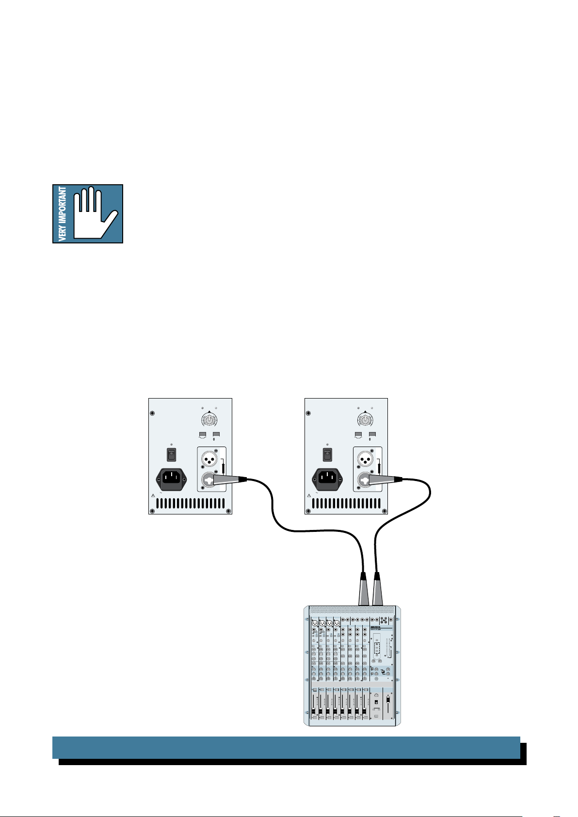
2. Connect the output from your signal source (mixing
console, microphone, preamp, or other mic- or line-level source) directly to the INPUT connector on the back
of the SRM350 v2. This is a combination XLR and 1/4"
TRS connector, and accepts balanced or unbalanced
line-level signals from mixers, preamplifiers, CD players, tape decks, etc., with the MIC/LINE switch out, and
accepts direct connections from dynamic microphones
with the MIC/LINE switch pushed in.
3. Connect the supplied AC power cord to the IEC socket
on the back of the SRM350 v2. Plug the other end into
an AC outlet properly configured with the correct voltage for your particular model.
4. Turn on your signal source. Make sure its Master Vol
ume control (if it has one) is turned all the way down.
5. Turn on the SRM350 v2 POWER switch.
6. Start the signal source, whether it be speaking into a
microphone or starting a CD player. Adjust any volume
controls on the signal source for normal operation.
7. Slowly turn up the LEVEL control on the back of the
SRM350 v2 until the desired volume is reached (and
the LIMIT light does not come on). Always wear hearing protectors if you are close when it is playing at high
levels.
8. If there is no sound,
always turn down the SRM350 v2
LEVEL control before investigating. There may be a
mixer or preamplifier mute or tape switch engaged, or a
mic switch off.
-
SRM350 v2: STEREO OPERATION WITH A MIXER
 Loading...