

Page 1
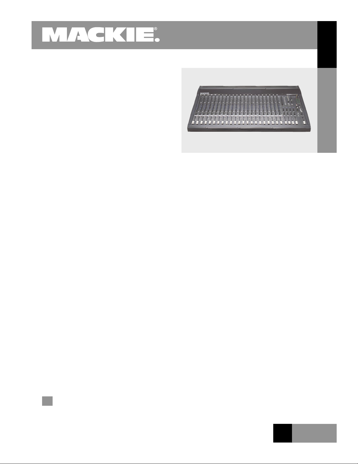
SR24•4-VLZ PRO
™
24-Channel Sound Reinforcement Console
Introduction
THE SR24•4-VLZ PRO is the latest update of our SR24•4
sound reinforcement console, incorporating our ultra-high
quality XDR™ (Extended Dynamic Range) mic preamps with
the best RFI rejection of any sound reinforcement mixer
design on the market.
Like all Mackie mixers, the SR24•4-VLZ PRO is designed
for rugged, 24-hour-a-day use. With its multiple input/
output congurations, true 4-bus architecture, 6 aux
sends, and extensive routing capabilities, it can be used
in a variety of live sound and recording applications. Its
sturdy steel construction houses rugged, double-sided
SMT-plated berglass circuit boards, and 60 mm faders
with ultra-tight lip seals for keeping out dust and other
contaminants. Impact-resistant knobs are mounted so they
“ride” just above the steel chassis.
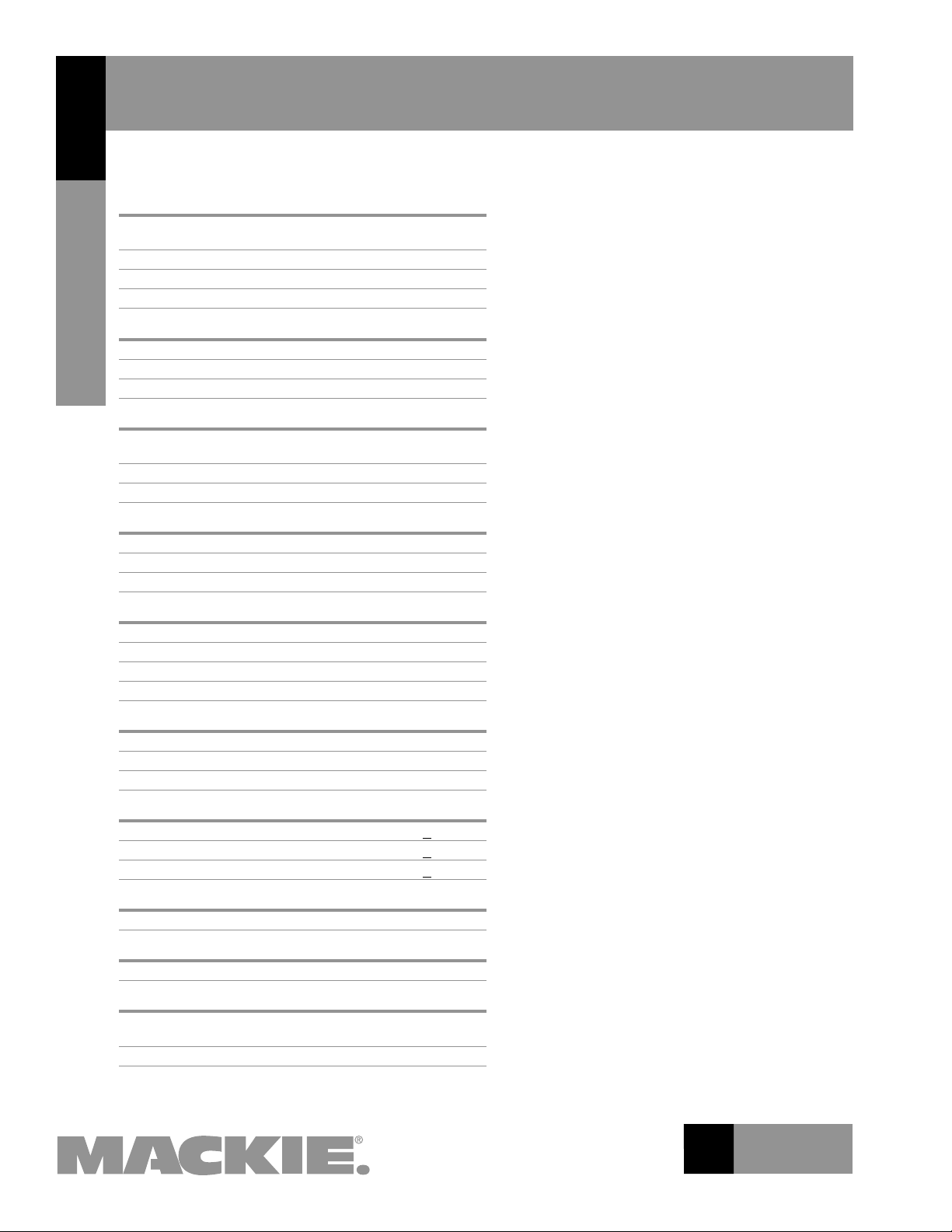
The SR24•4-VLZ PRO has 20 mono mic/line input chan-
nels, with XLR mic inputs and 1/4" TRS line inputs, and 2
stereo line input channels with 1/4" TRS inputs. All mono
channels have TRS insert jacks (tip = send, ring = return).
Each channel strip has an input trim, 6 aux sends (2 prefader, 2 post-fader, and 2 switchable pre or post), 3-band
EQ with sweepable midrange (4-band EQ on the stereo channels), pan control, and mute, solo, and bus assign switches.
A 60 mm fader provides output gain for each channel.
Twenty XDR mic preamps provide high-headroom and
low-noise. They are impedance-independent, so the
quency response remains constant whether the mic preamp
is presented with an extremely high- or low-impedance
load. Additionally, each channel has its own switchable
low-cut lter (18 dB/octave @ 75 Hz).
The mono channel EQs provide a range of ±15 dB at the
following frequencies: 12 kHz shelving high-frequency EQ,
100 Hz to 8 kHz sweepable peaking mid-frequency EQ,
and 80 Hz shelving low-frequency EQ. The stereo channels
(21-24) provide ±15 dB of boost and cut at the following
frequencies: 12 kHz shelving high-frequency EQ, 3 kHz
peaking high-mid frequency EQ, 800 Hz peaking low-mid
frequency EQ, and 80 Hz shelving low-frequency EQ.
(continued on page 2)
fre-
Features
Low noise/high headroom XDR™ (Extended Dynamic
Range) mic preamps with excellent RFI rejection
New high-performance 2068 op-amps for incredibly low
noise and distortion
Improved cooling for even greater thermal protection
20 mic/line mono, and 2 stereo line channels
True 4-bus design
Solo, pan, and 16 kHz Air EQ on each submaster
6 individual aux sends per channel (2 pre, 2 post,
2 switchable pre/post)
3-band swept midrange EQ on mic channels;
4-band xed on stereo line channels
75 Hz low-cut lters on mic channels
Mute, solo, signal present and OL LEDs on every channel
6 aux send masters with individual solos
4 stereo aux returns with EFX monitor
Separate Talkback section with mic preamp
Double-bused sub outs for easy multi-track routing
Balanced stereo TRS & XLR main outputs
Balanced XLR mono output with level control
MIXER
SR24•4-VLZ PRO
R E L A T E D P R O D U C T S
SR32•4-VLZ PRO
Applications
Live sound mixing
Multi-track recording
O F 8 P A G E S
1
Page 2
24-Channel Sound
SR24•4-VLZ PRO
MIXER
Specications
Noise
(20 Hz to 20 kHz bandwidth, Line inputs to Main L/R outputs,
all channels assigned, panned L/R):
Master fader down, Ch. gains down –94.7 dBu
Master fader @ unity, Ch. gains down –87.4 dBu
Master fader @ unity, Ch. gains @ unity –83.5 dBu
Total Harmonic Distortion
(1 kHz @ +14 dBu, 20 Hz-20 kHz):
Mic input insert output <0.0007%
SR24•4-VLZ PRO
Other outputs <0.004%
Crosstalk
(1 kHz @ 0 dBu, 20 Hz to 20 kHz bandwidth, channel in to
Main Left outputs):
Channel fader down, channels at Unity –89.5 dB
Channel muted, channels 2-16 at Unity –88.7 dB
Frequency Response
(any input to any output):
20 Hz to 60 kHz +0/–1dB
10 Hz to 100 kHz +0/–3dB
Maximum Levels
Mic preamp input +22 dBu
All other inputs +22 dBu
Balanced XLR outputs +28 dBu
All other outputs +22 dBu
Impedances
Mic preamp input 1.5 kΩ
All other inputs >10 kΩ
All outputs 120 Ω
Equalization
Lo EQ Shelving 80 Hz +15 dB
Mid EQ (mono ch) Peak 100 Hz-8 kHz +15 dB
Hi EQ Shelving 12 kHz +15 dB
Microphone Preamp
E.I.N. (150 Ω terminated, max gain) –129.5 dBm
Power Requirements
60 watts
Reinforcement Console
(continued from page 1)
Channels can be assigned to buses 1-2, 3-4, and
Main Mix L/R, and the 4 subs can be assigned to
Left
and Right Main Mix. Furthermore, each bus is
“double-bused,”
connected to an 8-track recorder without repatching.
Each sub out (1-4) and main out (L/R) has a TRS insert
jack. Furthermore, Mackie’s unique “AIR” EQ circuit is
included on each of the four subgroups. It provides a
gentle nudge to the extreme high-end, without affecting lower treble octaves.
Outputs include XLR and 1/4" TRS line outputs for
the left and right mains, 1/4" TRS line outputs for
subs 1-4, and an XLR mono main output. The mono
main out has its own level control, so a mono mix can
be sent to another zone and adjusted accordingly.
The Phones/Control Room switch and level control
are connected to two stereo headphone outputs and
the left and right Control Room output, allowing the
stereo Tape Return, Left/Right Main Mix, and Solo to
be monitored.
A stereo playback device can be monitored via the
Tape Return Inputs. Tape Return to Phones/C-R routes
the tape playback signal into the monitor system and
meters, and the Tape Return knob adjusts the level of
playback, which can be monitored via headphones.
Tape Return signals can also be assigned directly to
the Main Mix. The SR24•4-VLZ PRO also has RCA-style
Tape Outs for output to conventional stereo recording
devices.
Each of the six aux sends has its own individual
master send control, driving 1/4" TRS output jacks.
Six stereo aux returns are provided, with 1/4" TRS
input jacks. Two aux returns can be folded back into
Aux Sends 1 and 2 via their own volume controls to
add effects in stage monitors.
An XLR input is provided for a talkback mic, which
can be assigned to the Main Mix or to Aux 1-2. The
talkback mic has a level control in the talkback section.
providing eight outputs that can be
Physical
Dimensions (HxWxD): 5.60" x 31" x 19.20"
142.24 mm x 787.40 mm x 487.68 mm
Net Weight: 24•4-VLZ PRO 31 lbs (14 kg)
2
O F 8 P A G E S
Page 3
SR24•4-VLZ PRO
24-Channel Sound
Reinforcement Console
O F 8 P A G E S
dB
30
20
10
OO
40
50
5
5
U
60
10
dB
30
20
10
OO
40
50
5
5
U
60
10
dB
30
20
10
OO
40
50
5
5
U
60
10
dB
30
20
10
OO
40
50
5
5
U
60
10
dB
30
20
10
OO
40
50
5
5
U
60
10
dB
30
20
10
OO
40
50
5
5
U
60
10
dB
30
20
10
OO
40
50
5
5
U
60
10
dB
30
20
10
OO
40
50
5
5
U
60
10
dB
30
20
10
OO
40
50
5
5
U
60
10
dB
30
20
10
OO
40
50
5
5
U
60
10
dB
30
20
10
OO
40
50
5
5
U
60
10
dB
30
20
10
OO
40
50
5
5
U
60
10
dB
30
20
10
OO
40
50
5
5
U
60
10
dB
30
20
10
OO
40
50
5
5
U
60
10
dB
30
20
10
OO
40
50
5
5
U
60
10
dB
30
20
10
OO
40
50
5
5
U
60
10
dB
30
20
10
OO
40
50
5
5
U
60
10
dB
30
20
10
OO
40
50
5
5
U
60
10
dB
30
20
10
OO
40
50
5
5
U
60
10
dB
30
20
10
OO
40
50
5
5
U
60
10
dB
30
20
10
OO
40
50
5
5
U
60
10
dB
30
20
10
OO
40
50
5
5
U
60
10
dB
30
20
10
OO
40
50
5
5
U
60
10
dB
30
20
10
OO
40
50
5
5
U
60
10
dB
30
20
10
OO
40
50
5
5
U
60
10
dB
30
20
10
OO
40
50
5
5
U
60
10
dB
30
20
10
OO
40
50
5
5
U
60
10
OO
U
OO
+15
U
OO
+15
OO
U
OO
+15
MAX
MA
X
U
OO
+20
U
OO
+20
U
OO
+20
U
OO
+20
U
OO
+20
U
OO
+15
U
OO
+15
U
OO
+15
U
OO
+15
U
OO
+15
U
OO
+15
5
+100
5
+100
5
+100
5
+100
L R L R L R L R L R L R L R L R L R L R L R L R L R L R L R L R L R L R L R L R L R L R
U
OO
+15
U
OO
+15
U
OO
+15
U
OO
+15
U
+15-15
U
+15-15
U
+15-15
U
OO
+15
U
OO
+15
U
OO
+15
U
OO
+15
U
OO
+15
U
OO
+15
U
+15-15
U
+15-15
U
+15-15
U
OO
+15
U
OO
+15
U
OO
+15
U
OO
+15
U
OO
+15
U
OO
+15
U
+15-15
U
+15-15
U
+15-15
U
OO
+15
U
OO
+15
U
OO
+15
U
OO
+15
U
OO
+15
U
OO
+15
U
+15-15
U
+15-15
U
+15-15
U
OO
+15
U
OO
+15
U
OO
+15
U
OO
+15
U
OO
+15
U
OO
+15
U
+15-15
U
+15-15
U
+15-15
U
OO
+15
U
OO
+15
U
OO
+15
OO
+15
OO
+15
U
OO
+15
U
+15-15
U
+15-15
U
+15-15
U
OO
+15
U
OO
+15
U
OO
+15
OO
+15
U
OO
+15
U
OO
+15
U
+15-15
U
+15-15
U
+15-15
U
OO
+15
U
OO
+15
U
OO
+15
OO
+15
U
OO
+15
U
OO
+15
U
+15-15
U
+15-15
U
+15-15
U
OO
+15
U
OO
+15
U
OO
+15
U
OO
+15
U
OO
+15
U
OO
+15
U
+15-15
U
+15-15
U
+15-15
U
OO
+15
U
OO
+15
U
OO
+15
U
OO
+15
U
OO
+15
U
OO
+15
U
+15-15
U
+15-15
U
+15-15
U
OO
+15
U
OO
+15
U
OO
+15
U
OO
+15
U
OO
+15
U
OO
+15
U
+15-15
U
+15-15
U
+15-15
U
OO
+15
U
OO
+15
U
OO
+15
U
OO
+15
U
OO
+15
U
OO
+15
U
+15-15
U
+15-15
U
+15-15
U
OO
+15
U
OO
+15
U
OO
+15
U
OO
+15
U
OO
+15
U
OO
+15
U
+15-15
U
+15-15
U
+15-15
U
OO
+15
U
OO
+15
4
U
OO
+15
U
OO
+15
U
OO
+15
U
OO
+15
U
+15-15
U
+15-15
U
+15-15
U
OO
+15
U
OO
+15
U
OO
+15
U
OO
+15
U
OO
+15
U
OO
+15
U
+15-15
U
+15-15
U
+15-15
U
OO
+15
U
OO
+15
U
OO
+15
U
OO
+15
U
OO
+15
U
OO
+15
U
+15-15
U
+15-15
U
+15-15
U
OO
+15
U
OO
+15
U
OO
+15
U
OO
+15
U
OO
+15
U
OO
+15
U
+15-15
U
+15-15
U
+15-15
U
OO
+15
U
OO
+15
U
OO
+15
U
OO
+15
U
OO
+15
U
OO
+15
U
+15-15
U
+15-15
U
+15-15
U
OO
+15
U
OO
+15
U
OO
+15
U
OO
+15
U
OO
+15
U
OO
+15
U
+15-15
U
+15-15
U
+15-15
U
OO
+15
U
OO
+15
L R L R L R L R
U
OO
+15
U
OO
+15
U
OO
+15
U
OO
+15
U
+15-15
U
+15-15
U
+15-15
U
+15-15
U
+15-15
U
+15-15
U
+15-15
U
+15-15
U
+15-15
U
+15-15
U
+15-15
U
OO
+15
U
OO
+15
U
OO
+15
U
OO
+15
U
OO
+15
U
OO
+15
U
OO
+15
U
OO
+15
U
OO
+15
U
OO
+15
U
OO
+15
U
OO
+15
U
OO
+15
U
OO
+15
-
20 +2
0
U
-
20 +20
U
POST
POST
+15dB
-
45dB
M
I
C
G
A
I
N
0
U
60
-
1
0
d
B
V
POST
POST
+15dB
-
45dB
M
I
C
G
A
I
N
0
U
60
-
1
0
d
B
V
POST
POS
T
+15dB
-
45dB
M
I
C
G
A
I
N
0
U
60
-
1
0
d
B
V
POST
POST
+15dB
-
45dB
M
I
C
G
A
I
N
0
U
60
-
1
0
d
B
V
POST
POST
+15dB
-
45dB
M
I
C
G
A
I
N
0
U
60
-
1
0
d
B
V
POST
POS
T
+15dB
-
45dB
M
I
C
G
A
I
N
0
U
60
-
1
0
d
B
V
POST
POST
+15dB
-
45dB
M
I
C
G
A
I
N
0
U
60
-
1
0
d
B
V
POST
POST
+15dB
-
45dB
M
I
C
G
A
I
N
0
U
60
-
1
0
d
B
V
POST
POS
T
+15dB
-
45dB
M
I
C
G
A
I
N
0
U
60
-
1
0
d
B
V
POST
POST
+15dB
-
45dB
M
I
C
G
A
I
N
0
U
60
-
1
0
d
B
V
POST
POST
+15dB
-
45dB
M
I
C
G
A
I
N
0
U
60
-
1
0
d
B
V
POST
POST
+15dB
-
45dB
M
I
C
G
A
I
N
0
U
60
-
1
0
d
B
V
POST
POST
+15dB
-
45dB
M
I
C
G
A
I
N
0
U
60
-
1
0
d
B
V
POST
POST
+15dB
-
45dB
M
I
C
G
A
I
N
0
U
60
-
1
0
d
B
V
POST
POST
+15dB
-
45dB
M
I
C
G
A
I
N
0
U
60
-
1
0
d
B
V
POST
POST
+15dB
-
45dB
M
I
C
G
A
I
N
0
U
60
-
1
0
d
B
V
POST
POST
+15dB
-
45dB
M
I
C
G
A
I
N
0
U
60
-
1
0
d
B
V
POST
POST
+15dB
-
45dB
M
I
C
G
A
I
N
0
U
60
-
1
0
d
B
V
POST
POST
+15dB
-
45dB
M
I
C
G
A
I
N
0
U
60
-
1
0
d
B
V
POST POST
POST
POST
POST
POST
+15dB
-
45dB
M
I
C
G
A
I
N
0
U
60
-
1
0
d
B
V
600
1.5k150
8k100
600
1.5k150
8k100
600
1.5k150
8k100
600
1.5k150
8k100
600
1.5k150
8k100
600
1.5k150
8k100
600
1.5k150
8k100
600
1.5k150
8k100
600
1.5k150
8k100
600
1.5k150
8k100
600
1.5k150
8k100
600
1.5k150
8k100
600
1.5k150
8k100
600
1.5k150
8k100
600
1.5k150
8k100
600
1.5k150
8k100
600
1.5k150
8k100
600
1.5k150
8k100
600
1.5k150
8k100
600
1.5k150
8k100
16kHz16kHz16kHz16kHz
LAMP
12k
HI
3k
MID
HI
800Hz
MID
LOW
EQ
STEREO
AUX RETURNS
AUX SEND
MASTERS
LEVEL
5
6
12k
HI
3k
MID
HI
800Hz
MID
AIR AIR AIR AIR
LOW
SOLO SOLO SOLO SOLO
EQ
-20
OL
PR
E
1
PRE
PR
E
2
3
5
6
12k
HI
MID
FREQ
80Hz
LOW CUT
75 Hz
18dB/OC
T
LOW CUT
75 Hz
18dB/OCT
LOW CUT
75 Hz
18dB/OC
T
LOW CU
T
75 Hz
18dB/OCT
LOW CUT
75 Hz
18dB/OC
T
LOW CU
T
75 Hz
18dB/OCT
LOW CUT
75 Hz
18dB/OC
T
LOW CUT
75 Hz
18dB/OCT
LOW CUT
75 Hz
18dB/OCT
LOW CUT
75 Hz
18dB/OCT
LOW CUT
75 Hz
18dB/OCT
LOW CU
T
75 Hz
18dB/OC
T
LOW CUT
75 Hz
18dB/OCT
LOW CUT
75 Hz
18dB/OCT
LOW CUT
75 Hz
18dB/OCT
LOW CUT
75 Hz
18dB/OCT
LOW CUT
75 Hz
18dB/OCT
LOW CUT
75 Hz
18dB/OCT
LOW CUT
75 Hz
18dB/OCT
LOW CUT
75 Hz
18dB/OCT
LOW
80Hz
LOW
80Hz
LOW
80Hz
LOW
80Hz
LOW
80Hz
LOW
80Hz
LOW
80Hz
LOW
80Hz
LOW
80Hz
LOW
80Hz
LOW
80Hz
LOW
80Hz
LOW
80Hz
LOW
80Hz
LOW
80Hz
LOW
80Hz
LOW
80Hz
LOW
80Hz
LOW
80Hz
LOW
80Hz
LOW
80Hz
LOW
TRIM
1
AUX
1
MUTE
EQ
1
2
3
4
1
2
1
2
3
4
SOLO
SOLO
1
-
2
SUB
SOLO
GLOBAL
AUX RETURN
ASSIGN
TO SUB
SOLO
SOLO
TAPE RETURN
TO PHONES / C
R
TAPE RETURN
TO MAIN MIX
LEFT/RIGHT
MAIN MI
X
AUX
1
-
2
TALKBACK
LEVEL
TAPE
RETURN
3
-
4
LEFT RIGHT
L/R ASSIGN L/R ASSIGN L/R ASSIGN L/R ASSIGN
SUB SUB SUB SUB
1 2 3 4
PHONES / C
-
R
LEVEL
MAIN MIX
SOLO
TO AUX
SEND
1
-
2
(EFX TO MONITOR)
SOLO
28
CLIP
10
74 22047
102030
40
3
-
4
L
-
R
1
-
2
3
-
4
L
-
R
1
-
2
3
-
4
L
-
R
1
-
2
3
-
4
L
-
R
1
-
2
3
-
4
L
-
R
1
-
2
3
-
4
L
-
R
1
-
2
3
-
4
L
-
R
1
-
2
3
-
4
L
-
R
1
-
2
3
-
4
L
-
R
1
-
2
3
-
4
L
-
R
1
-
2
3
-
4
L
-
R
1
-
2
3
-
4
L
-
R
1
-
2
3
-
4
L
-
R
1
-
2
3
-
4
L
-
R
1
-
2
3
-
4
L
-
R
1
-
2
3
-
4
L
-
R
1
-
2
3
-
4
L
-
R
1
-
2
3
-
4
L
-
R
1
-
2
3
-
4
L
-
R
1
-
2
3
-
4
L
-
R
1
-
2
3
-
4
L
-
R
1
-
2
3
-
4
L
-
R
1
-
2
-20
OL
PR
E
1
PRE
PR
E
2
3
5
6
12k
HI
MID
FREQ
TRIM
2
AUX
2
MUTE
EQ
-20
OL
PR
E
1
PRE
PR
E
2
3
5
6
12k
HI
MI
D
FREQ
TRIM
3
AUX
3
MUTE
EQ
-20
OL
PR
E
1
PRE
PR
E
2
3
5
6
12k
HI
MID
FREQ
TRIM
4
AUX
4
MUTE
EQ
-20
OL
PR
E
1
PRE
PR
E
2
3
5
6
12k
HI
MI
D
FREQ
TRIM
5
AUX
5
MUTE
EQ
-20
OL
PR
E
1
PRE
PR
E
2
3
5
6
12k
HI
MID
FREQ
TRIM
6
AUX
6
MUTE
EQ
-20
OL
PR
E
1
PRE
PR
E
2
3
5
6
12k
HI
MI
D
FREQ
TRIM
7
AUX
7
MUTE
EQ
-20
OL
PR
E
1
PRE
PR
E
2
3
5
6
12k
HI
MID
FREQ
TRIM
8
AUX
8
MUTE
EQ
-20
OL
PR
E
1
PRE
PR
E
2
3
5
6
12k
HI
MID
FREQ
TRIM
9
AUX
9
MUTE
EQ
-20
OL
PR
E
1
PRE
PR
E
2
3
5
6
12k
HI
MID
FREQ
TRIM
10
AUX
10
MUTE
EQ
-20
OL
PR
E
1
PRE
PR
E
2
3
5
6
12k
HI
MID
FREQ
TRIM
11
AUX
11
MUTE
EQ
-20
OL
PR
E
1
PRE
PR
E
2
3
5
6
12k
HI
MID
FREQ
TRIM
12
AUX
12
MUTE
EQ
-20
OL
PR
E
1
PRE
PR
E
2
3
5
6
12k
HI
MID
FREQ
TRIM
13
AUX
13
MUTE
EQ
-20
OL
PR
E
1
PRE
PR
E
2
3
5
6
12k
HI
MID
FREQ
TRIM
14
AUX
14
MUTE
EQ
-20
OL
PR
E
1
PRE
PR
E
2
3
5
6
12k
HI
MID
FREQ
TRIM
15
AUX
15
MUTE
EQ
-20
OL
PR
E
1
PRE
PR
E
2
3
5
6
12k
HI
MID
FREQ
TRIM
16
AUX
16
MUTE
EQ
-20
OL
PR
E
1
PRE
PR
E
2
3
5
6
12k
HI
MID
FREQ
TRIM
17
AUX
17
MUTE
EQ
-20
OL
PR
E
1
PRE
PR
E
2
3
5
6
12k
HI
MID
FREQ
TRIM
18
AUX
18
MUTE
EQ
-20
OL
PR
E
1
PRE
PR
E
2
3
5
6
12k
HI
MID
TRIM
19
AUX
19
MUTE
EQ
-20
OL
-20
OL
-20
OL
PR
E
1
PRE
PR
E
2
3
5
6
12k
HI
MID
FREQ
TRIM
20
TRIM
21
22
TRIM
23
24
AUX
PRE1PRE
PR
E
2
3
5
6
AUX
PRE1PRE
PR
E
2
3
5
6
AUX
20
MUTE
EQ
21 22
MUTE
23 24
TRACK
1•5
TRACK
2•6
TRACK
3•7
TRACK
4•8
MUTE
SOLO
MODE
SUBAUX
PRE FADER
IN PLACE AFL
LEVEL SET
SOLO
SOLO SOLO
SOLO SOLO SOLO SOLO SOLO SOLO SOLO SOLO SOLO SOLO SOLO SOLO SOLO SOLO SOLO SOLO SOLO SOLO SOLO
PANPANPAN PANPAN PAN PAN PAN PAN PAN PAN PAN PAN PAN PAN PAN PAN PAN PAN PAN PAN PAN PAN PAN PAN
4 4 4 4 4 4 4 4 4 4 4 4 4 4 4 4 4 4 4 4
4
POWERRUDE
SOLO
LIGHT
OPERATING LEVEL
0dB = 0dBu
PAN
MUTE /
SO
LO
MUTE /
SO
LO
MUTE /
SOLO
MUTE /
SOLO
MUTE /
SOLO
MUTE /
SOLO
MUTE /
SOLO
MUTE /
SOLO
MUTE /
SO
LO
MUTE /
SOLO
MUTE /
SOLO
MUTE /
SOLO
MUTE /
SOLO
MUTE /
SOLO
MUTE /
SOLO
MUTE /
SO
LO
MUTE /
SO
LO
MUTE /
SO
LO
MUTE /
SOLO
MUTE /
SOLO
MUTE /
SO
LO
MUTE /
SOLO
WITH PREMIUM XDR
TM
MIC PREAMPL IFIERS
SR SERIES 24•4•2 4
–
BUS MIXING CONSOLE
SR
24•4
-
VLZPRO
SR24•4-VLZ PRO
SR24•4-VLZ PRO Top
24-Channel Sound
Reinforcement Console
3
O F 8 P A G E S
Page 4

SR24•4-VLZ PRO
INSERT INSERT INSERT INSERT INSERT INSERT INSERT INSERT INSERT INSERT INSERT INSERT INSERT INSERT INSERT INSERT INSERT INSERT INSERT INSERT
MIC 20
TAPE OUTTAPE IN
TALK BACK
MI
C
R
R
R
(MONO)
4
L
L
L
3
2
1
L
CONTROL ROOM OUTMAIN INSERTS
3
342
3
1
1
L L
R
R R
L
24
23 21
22
20
MIC 19
19
LINE IN
(BAL OR UNBAL
)
LINE I
N
(BAL OR UNBAL
)
LINE I
N
(BAL OR UNBAL
)
LINE I
N
(BAL OR UNBAL)
LINE IN
(BAL OR UNBAL)
LINE I
N
(BAL OR UNBAL
)
LINE IN
(BAL OR UNBAL)
LINE I
N
(BAL OR UNBAL
)
LINE I
N
(BAL OR UNBAL)
LINE I
N
(BAL OR UNBAL)
LINE IN
(BAL OR UNBAL)
LINE IN
(BAL OR UNBAL)
LINE IN
(BAL OR UNBAL)
LINE IN
(BAL OR UNBAL)
LINE IN
(BAL OR UNBAL)
LINE IN
(BAL OR UNBAL)
LINE IN
(BAL OR UNBAL)
LINE IN
(BAL OR UNBAL)
LINE IN
(BAL OR UNBAL)
LINE I
N
(BAL OR UNBAL)
MIC 18
18
MIC 17
17
MIC 16
16
MIC 15
15
MIC 14
14
MIC 13
13
MIC 12
12
MIC 11
11
MIC 10 MIC 9
9
MIC 8
8
MIC 7
7
MIC 6
6
MIC 5
5
MIC 4
4
MIC 3
3
MIC 2
2
MIC 1
RIGHT
MAIN OUT
LEFT
MAIN OUT
MONO
MAIN OUT
OUTPUT
LEVEL
PHONES
2
PHONES
1
OFF
POWER
ON
OF
F
PHANTOM
ON
MONO MONO
PIN 2 = HOT
PIN 3 = COL
D
FUSE INSIDE
120VAC
50/60 HZ 60W
1A/250V SLO BLO
CAUTION: TO REDUCE
THE RISK OF FIRE, REPLACE
WITH THE SAME TYPE FUSE
AND RATING
OO
+6
MAIN
BALANCED
OUTPUTS
R
R
L
L
AUX SENDS
(BAL OR UNBAL)
STEREO AUX RETURNS
(BAL OR UNBAL)
SUB INSERTS
(BAL OR UNBAL)
6
2
5
1 4
R
R
L
R
L
786
5
SUB OUTS
(BAL OR UNBAL)
4
2
MAIN OUTS
(BAL OR UNBAL)
(BAL OR UNBAL
)
THE FOLLOWING ARE TRADEMARKS OR REGISTERED TRADEMARKS OF MACKIE DESIGNS INC.: "MACKIE.", AND THE "RUNNING MAN" FIGURE • US PATENT NUMBER Des. 380,760
XDR
TM
EXTENDED DYNAMIC RANGE MIC PREAMPLIFIERS ARE PROPRIETARY TO MACKIE DESIGNS INC.
X
D
R
M
I
C
P
R
E
X
D
R
M
I
C
P
R
E
X
D
R
M
I
C
P
R
E
X
D
R
M
I
C
P
R
E
X
D
R
M
I
C
P
R
E
X
D
R
M
I
C
P
R
E
X
D
R
M
I
C
P
R
E
X
D
R
M
I
C
P
R
E
X
D
R
M
I
C
P
R
E
X
D
R
M
I
C
P
R
E
X
D
R
M
I
C
P
R
E
X
D
R
M
I
C
P
R
E
X
D
R
M
I
C
P
R
E
X
D
R
M
I
C
P
R
E
X
D
R
M
I
C
P
R
E
X
D
R
M
I
C
P
R
E
X
D
R
M
I
C
P
R
E
X
D
R
M
I
C
P
R
E
X
D
R
M
I
C
P
R
E
X
D
R
M
I
C
P
R
E
110
TIP OUT TO EFFECTS DEVICE
RING RETURN FROM EFFECTS
STEREO
PLUG
INSERT
MANUFACTURING DATE
RISK OF ELECTRIC SHOCK
DO NOT OPEN
REPLACE WITH THE SAME TYPE FUSE AND RATING.
DISCONNECT SUPPLY CORD BEFORE CHANGING FUSE
UTILISE UN FUSIBLE DE RECHANGE DE MÊME TYPE.
DEBRANCHER AVANT DE REMPLACER LE FUSIBLE
WARNING:
TO REDUCE THE RISK OF FIRE OR ELECTRIC SHOCK, DO NOT
EXPOSE THIS EQUIPMENT TO RAIN OR MOISTURE. DO NOT REMOVE COVER.
NO USER SERVICEABLE PARTS INSIDE. REFER SERVICING TO QUALIFIED PERSONNEL.
AVIS:
RISQUE DE CHOC ELECTRIQUE — NE PAS OUVRIR
CAU TI ON
SERIAL NUMBER
CONCEIVED, DESIGNED, AND MANUFACTURED
BY MACKIE DESIGNS INC. • WOODINVILLE • WA
98072 • USA • MADE IN USA • FABRIQUE AU US
A
24•4•2 4 BUS MIXING CONSOLE
WITH PREMIUM XDR
TM
MIC PREAMPLIFIERS
24•4-VLZPRO
SR24•4-VLZ PRO Rear Panel
24-Channel Sound
Reinforcement Console
4
O F 8 P A G E S
Page 5

24-Channel Sound
31.00"
5.60"
2.80"
18.90"
1.30"
1.80"
2.80"
0.50"
19.20"
19.20"
24•4
WEIGHT
31 lbs.
SR24•4-VLZ PRO
SR24•4-VLZ Pro Dimensions
Reinforcement Console
5
O F 8 P A G E S
Page 6

24-Channel Sound
•••
•
•
•
•
•
•
•
• •
•
•
••
• •
•
•
•
•
•
•
•
•
•••
•
•
•
•
•
•
•
•
•
•
•
•
•
•
•
•
•
•
•
•
•
•
•
•••
•
•
•
•
•
•
•
•
•
•
•
•
•
•
•
•
•
•
•
•
•
•
•
•
•
•
•
•
•
•
•
•
•
•
•
•
•
•••
•
•
•
•
•
•
•
•
•
•
•
•
•
•
•
•
•
•
••
•
•
•
•
•
•
•
•
•
•
•
•
•
•
•
•
•
•
•
•
•
•
•
•
•
•
•
•
•
•
•
•
•
•
•
•
•
•
•
•
1
2
3
TRIM: MIC GAIN-
0 to +60 dB
LINE GAIN-
-15 to +45 dB
LO CUT
MUTE
INSERT
-20 dB LED
EQ
LO MID HI
80 8k 12k
100-
GAIN
FREQ
GAIN
GAIN
FADER
PAN
O/L LED
ASSIGN
SWITCHES
1-2
3-4
L-R
SOLO IN
PLACE
PFL
LOGIC
MUTE
LED
AUX 1
AUX 2
AUX 3
AUX 4
AUX 5
AUX 6
PRE
MONO
INPUT
CHANNEL
(1 of 20)
SR24•4-VLZ PRO
BLOCK DIAGRAM REV 1 3/28/2000
BOLD LINES INDICATE
SIGNAL PATH FROM MIC
INPUT TO LEFT MAIN OUTPUT.
LEFT
(MONO)
RIGHT
TRIM
-20dB
LED
LO LO- HI- HI
MID MID
LO LO- HI- HI
80 800 3k 12k
MID MID
O/L
LED
FADER
PRE-FADER
PRE-FADER
POST-FADER
POST-FADER
LINE GAIN-
-20 TO +20dB
+
-
+
-
+
-
MUTE
LED
AUX 1
AUX 2
AUX 3
AUX 4
AUX 5
AUX 6
PRE
STEREO
INPUT
CHANNEL
(1 OF 2)
TALKBACK
XLR INPUT
LEVEL
TB TO AUX 1-2
TB TO L-R MIX
1-2
3-4
L-R/SUBS
LEVEL
AUX RET 4 IN
AUX RET 3 IN
AUX RET 1 (2) IN
LEVEL
LEVEL
SOLO
SOLO LED
AUX
SEND
(1 OF 6)
AUX 1
OUTPUT
+
-
+
-
+
-
+
-
+
-
+
-
L
L
L
R
R
R
L
R
PHONES
OUTPUTS
PHONES
AMPS
RELAY
AUX SEND 1 (2)
SOLO
LEVEL
PFL/SIP
LEVEL
RUDE SOLO LED
TAPE TO
MONITOR
L
R
CONTROL
ROOM OU
T
SOLO RELAY
TAPE IN
R MIX
L MIX INSERTS FADER
RIGHT
XLR
OUT
LEFT
XLR
OUT
MONO
XLR
OUT
RIGHT
OUT
R
L
TAPE OUT
LEFT
OUT
MONO
LEVEL
SUB
OUT
1
SUB
OUT
5
FADER
SUB OUT 1 (1 OF 4)
ASSIGN
TO L-R
PAN
TAPE TO L-R
SOLO
PFL
LOGIC
GAIN
AIR
16kHz
MIC
IN
LINE
IN
+22
+10
+7
+4
+2
0
-2
-4
-7
-10
-20
-30
-40
METERS
SUB 1
SUB
2
SUB
3
SUB
4
AUX 1
AUX
2
AUX
3
AUX
4
AUX 5
AUX
6
L MIX
R MI
X
SOLO
L
SOLO
R
PFL
LOGIC
•
•
•
Vp
•
•
•
•
•
•
SOLO
•
∑
LEVEL
ØdBu=Ø VU
∑
∑
•
∑
∑
∑
∑
∑
•
•
∑
∑
MONITOR LEVEL
1
2
3
1
2
3
1
2
3
•
•
•
∑
∑
∑
•
•
•
1-2
3-4
L-R
SOLO IN
PLACE
PFL
LOGIC
•
80 800 3k 12k
•
•
•
•
PAN
INSERT
•
•
•
•
MUTE
PHANTOM POWER
(GLOBAL SWITCH)
MACKIE XDR
MIC PREAMP
75Hz
HPF
SR24•4-VLZ PRO
SR24•4-VLZ PRO Block Diagram
6
O F 8 P A G E S
Reinforcement Console
Page 7

24-Channel Sound
SR24•4-VLZ PRO
Architects’ and Engineers’ Specications
1. GENERAL CONFIGURATION. The audio mixer shall
have a free-standing frame tted with four resilient
feet suitable for tabletop placement. The frame shall
be comprised of 20 monaural input channels, 2 stereo
input channels, 4 submix output channels and 2 main
output channels. The monaural input channels shall be
capable of accepting either microphone- or line-level
signals, and shall be tted with trim, equalization, balance, and auxiliary send controls; solo, mute, and bus
assign switches; level-indicating LEDs and insert jacks.
The stereo input channels shall be capable of accepting either stereo or monaural line-level signals, and
shall be tted with stereo trim, equalization, balance,
and auxiliary send controls; solo, mute and bus assign
switches; and level indicating LEDs. The submix outputs
shall each have level, pan, and “air” controls; solo and
assign switches; and a bus access insert jack. The main
outputs shall share a stereo master output fader and
shall be tted with insert jacks. Additionally, the mixer
shall include a pre-fader/post fader solo function, a
main monaural output with level control derived from the
main stereo outputs, 6 monitor/effects send outputs, 4
stereo effects return inputs with switching and control
functions, 1 stereo control room monitor output, 2 stereo
headphone outputs, 1 set of stereo tape recorder convenience outputs, and 1 set of stereo tape monitor inputs.
2. POWER SUPPLY.
the mixer shall be provided by an internal power supply.
3. INPUT CHANNEL CONNECTIONS. Each monaural channel (1-20) shall include an XDR™ (Extended
Dynamic Range) electronically balanced microphone
input, using an XLR-3-F-type connector, accepting
nominal levels from –60 dBu to +4 dBu via a rotary Trim
control. Phantom power shall be globally controlled via
a rocker-type switch. Each monaural input channel shall
also have an electronically balanced line level input,
accommodating a nominal line level of between –10 dBV
and +4 dBu, and appearing on the rear panel as a 1/4"
TRS phone jack. Each stereo input channel shall have
left and right electronically balanced line level input,
accommodating a nominal line level of between –10 dBV
and +4 dBu, and appearing on the rear panel as 1/4"
TRS phone jacks. These jacks shall be tted with internal
switching contacts to accommodate monaural conguration. Additionally, each of the monaural input channels
(1-20) shall offer an unbalanced insert connection,
appearing on the rear panel as a 1/4" TRS phone jack.
4. INPUT CHANNEL LEVEL AND ASSIGNMENT
CONTROLS AND INDICATORS. Each monaural input chan-
nel shall be equipped with a preamplier gain control,
a solo switch, a mute switch, three bus assignment
All necessary operating voltages for
Reinforcement Console
switches, and a stereo pan control. Each stereo input
channel shall be equipped with a dual preamplier gain
control, a solo switch, a mute switch, three bus assignment switches and a stereo balance control.
5. INPUT CHANNEL EQUALIZATION. Each monaural
input channel shall be equipped with an equalization
function. The equalizer shall have three sections: a lowfrequency shelving equalizer with the knee set at 80 Hz
and a range of +15 dB; a mid-frequency peaking equalizer with a center frequency sweepable from a range of
100 Hz to 8 kHz, and a range of +15 dB; and a high-frequency shelving equalizer with the knee set at 12 kHz
and a range of +15 dB. Each stereo input channel shall
be equipped with a stereo equalization function. The
equalizer shall have four sections: a low-frequency shelving equalizer with the knee set at 80 Hz and a range of
+15 dB; a low-mid-frequency peaking equalizer centered
at 800 Hz and a range of +15 dB; a high-mid-frequency
peaking equalizer centered at 3.5 kHz and a range of
+15 dB; and a high frequency shelving equalizer with the
knee set at 12 kHz and a range of +15 dB.
6. INPUT CHANNEL AUXILIARY SENDS. Each mixer
input channel shall have 6 monaural auxiliary send controls. Two auxiliary send controls shall be xed as prefader sends; two shall be xed as post-fader sends; and
two shall be switchable between pre-fader and post-fader. All auxiliary sends shall be post-mute switch.
7. MAIN OUTPUT CONNECTIONS. The mixer shall have
electronically balanced, line-level left and right main
outputs, appearing on male XLR-3 type connectors and
impedance balanced on 1/4" phone TRS jacks on the rear
panel. Additionally, the main buses shall offer left and
right unbalanced insert connections, appearing on
rear panel as 1/4" phone TRS jacks. Further, there shall be
a main, electronically balanced, monaural output derived
from the main stereo output, appearing as a male XLR-3
type connector on the rear panel. There shall be an output
level control to adjust the main monaural output level.
8. OTHER OUTPUT AND MONITORING CONNECTIONS.
The mixer shall have the following impedance balanced
line-level connections, appearing as 1/4" TRS jacks on
the rear panel: submix bus outputs 1-4, also wired in
parallel respectively to submix outputs 5-8; left and right
control room monitor outputs, left and right tape monitor
outputs, left and right tape monitor inputs. For convenience, the left and right main outputs (unbalanced) and
the left and right tape monitor inputs shall also appear
as RCA phono jacks on the rear panel. There shall also be
two stereo headphone outputs on the rear panel of the
mixer, carrying the control room monitor signals at levels
and impedances proper for headphones. Each headphone output connection shall be a stereo 1/4" jack.
the
MIXER
SR24•4-VLZ PRO
7
O F 8 P A G E S
Page 8

24-Channel Sound
SR24•4-VLZ PRO
MIXER
9. OUTPUT AND MONITORING CONTROLS AND SWITCHES.
The mixer shall include one linear fader control for gain
adjustment of main L/R outputs, covering a range from
innite attenuation to +10 dB above unity gain. A tape
monitor switch shall alternately select either the main L/R
outputs or the signal at the tape inputs as the source for
the control room and headphones monitoring circuits.
There shall be a stereo dual-channel rotary control for gain
adjustment of the control room and headphone monitor
output. The mixer shall have a stereo dual-channel control
for adjustment of the monitoring level of the internal solo
SR24•4-VLZ PRO
signals, and a light to indicate channel solo condition.
The solo system shall be capable of switching between
PFL (pre-fader listen) and AFL (after-fader listen––solo in
place) operation.
10. OUTPUT METERING. The mixer frame shall include
two 13-segment LED meters each displaying a signal range
from –40 dBU to +10 dBu, each with an additional LED
indicating mixer clipping level at +22 dBu. The meters
shall monitor the main left and right output channels;
alternately, the meters shall monitor the tape return signals when the tape monitor switch is depressed; or, the
soloed input channel signals when the solo switch is
depressed.
11. AUXILIARY SEND CONNECTIONS. The mixer shall
include impedance balanced, line-level outputs from the
six auxiliary send buses, appearing on the rear panel as
1/4" TRS phone jacks.
12. AUXILIARY RETURN CONNECTIONS. The mixer shall
include 4 stereo auxiliary return inputs. Each auxiliary
return shall have a left and a right balanced line-level
input, accommodating a nominal line level of between
–10 dBu
as 1/4" TRS phone jacks. The jacks shall be tted with
internal switching contacts to accommodate monaural
conguration.
and +4 dBu, and shall appear on the rear panel
Reinforcement Console
13. AUXILIARY RETURN CONTROLS AND SWITCHES. The
mixer shall include 4 dual-channel auxiliary return gain
controls, each feeding the main stereo buses. Auxiliary
returns 1-2 shall have their signals assignable to auxiliary
send buses 1 and 2, respectively, through rotary level controls. Auxiliary return 4 shall be assignable to three different pairs of destinations, feeding either the main left and
right buses or the submix buses.
14. PHYSICAL CONFIGURATION. The mixer shall have
a steel chassis frame painted grey-black and designed to
rest on a horizontal surface. The SR24•4-VLZ PRO’s dimensions shall be 6.1" (155mm) high by 31" (787mm) wide by
19.2" (487mm) deep.
15. SPECIFICATIONS. In addition to specications
previously cited, the mixer shall meet or exceed the following specications. Frequency response, microphone
input to any output, 20 kHz to 60 kHz, +0 dB/ –1 dB;
Total Harmonic Distortion (THD), any input to any output,
1 kHz @ +14dBu, 0.004%; Equivalent Input Noise (EIN),
microphone input to insert send, –129.5 dBm; Common
Mode Rejection (CMR), microphone input to insert send,
maximum gain, 1 kHz, better than 90 dB; Typical Main
Output noise, all channels assigned, odd channels panned
left, even channels panned right, all faders down –94.7
dBu; Signal to Noise ratio, ref +4 dBu operating level, 90
dB; Attenuation, ref. 0 dB @ 1 kHz, Main Mix level control down, –85 dBu; Channel Mute engaged, –84 dBu;
Channel Gain control down, –83 dBu; Input impedance,
microphone inputs, 1.5 kΩ; Channel Insert return, 2.5 kΩ;
all other inputs, greater than 10 kΩ; Output impedance,
Tape Out, 1.1 kΩ; All other outputs, 120Ω.
16. DESIGNATION. The mixer shall be a Mackie
SR24•4-VLZ PRO.
www.mackie.com
16220 Wood-Red Road NE, Woodinville, WA 98072 USA
800.898.3211, fax 425.487.4337, sales@mackie.com
UK +44.1268.570.808, fax +44.1268.570.809, uk@mackie.com
Electronic les for this product available at:
www.mackie.com/installed
This Specication Sheet SR24VLZPRO_SS.PDF
Owner/Operator’s Manual SRVLZPRO_OM.PDF
LOUD Technologies continually engages in research related to product improvement. New material,
production methods, and design renements are introduced into existing products without notice as
a routine expression of that philosophy. For this reason, any current LOUD Technologies product may
differ in some respect from its published description, but will always equal or exceed the original
design specications unless otherwise stated. ©1999–2004 LOUD Technologies Inc. All rights
reserved. Mackie and the “Running Man” gure are registered trademarks of LOUD Technologies Inc.
Part No. 0003711 Rev A2 9/04
O F 8 P A G E S
8
 Loading...