

Page 1

SR1522z REPAIR MANUAL
1
Page 2

These instructions are intended to help restore any ailing SR1522z Active
Loudspeaker back to factory working conditions. They show how to remove and
replace the drivers and the amplifi er assembly.
Please contact Mackie Tech Support (1-800-898-3211) to receive a Service
Request Number and Order Number for parts needed for this restoration. They will
also help you determine the nature of the problem and what parts will repair the unit.
Tools needed:
***NOTE: not all tools listed below will be needed for your repair***
• Phillips head screwdriver.
• 3mm and 5mm allen wrenches.
• 8mm open end wrench.
• Solid workbench.
2
• Non-carpeted work area due to static electricity. If available, an ESD mat
(Electro-static discharge) is optimal.
Parts needed:
***NOTE: not all parts listed below will be needed for your repair***
• Led PCB Assembly Part #0007334 pages 3-4
• 15” Woofer (Bottom) Part #0013913 pages 5-6
• 15” Woofer (Top) Part #0013913 pages 7-9
• High Frequency Driver Part #0008093 pages 10-13
• Diaphragm Part #coming soon pages 14-15
• Amplifi er Assembly Part #0014138-00 pages 16-19
Safety Warnings:
• Make sure that you turn off the unit and disconnect the power cord (and all
other cords) before you begin these procedures.
• Always use safety glasses!
• Please try NOT to touch any of the pcb circuitry, capacitors, resistors, etc.
• Take care to read and follow these instructions. It may help to read the
instructions prior to the repair to get an idea of what it entails.
• Before beginning the repair, touch metal to discharge any lingering internal
static electricity.
Page 3
Led PCB replacement:
3
1
2
3
4
5
Five screws need to be removed from
1
7
8
9
10
each side of the grill (ten screws total)
using the phillips head screwdriver.
6
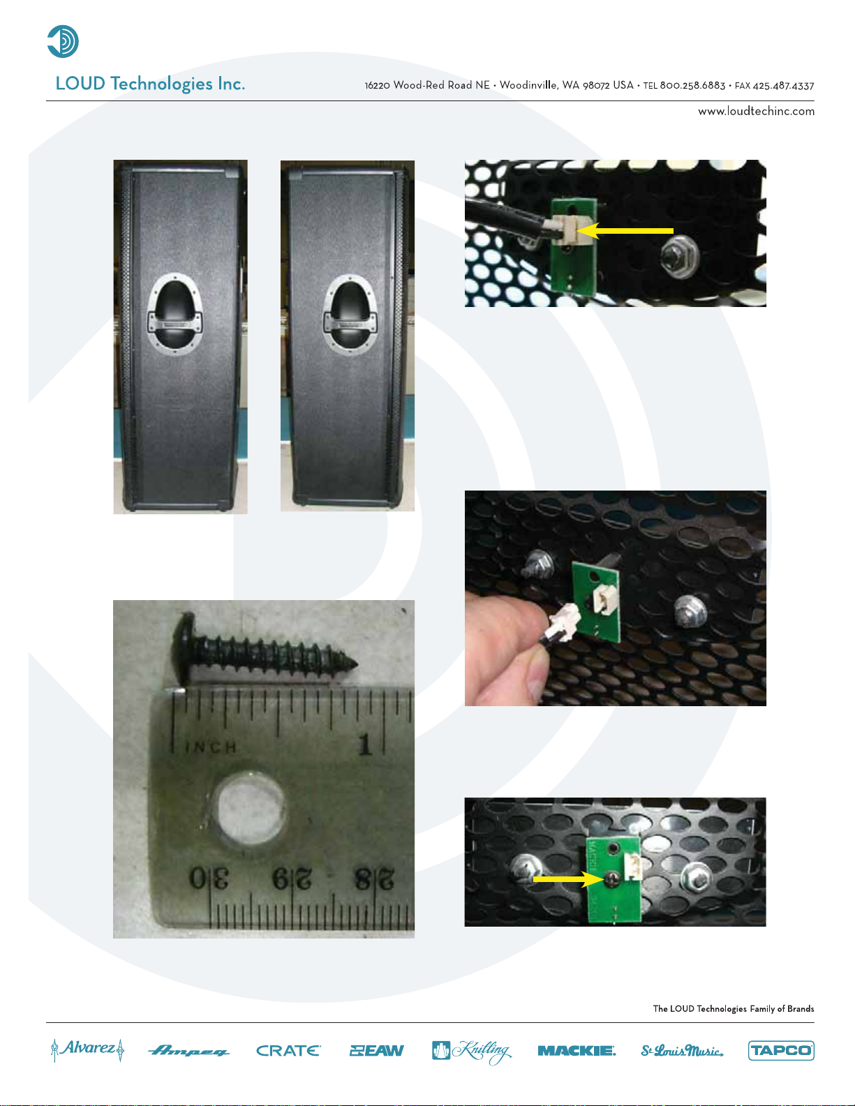
Carefully begin to remove the grill. The
3
grill has a tendency to want to “pop
out,” so please be sure to hold the
grill in place with your free hand while
removing the screws with the other
hand. Do not fully remove the grill as the
cable is still fi rmly attached to the led
PCB assembly.
Keep the ten screws in a safe place.
2
Carefully remove the cable attached to
4
Use the phillips head screwdriver to
5
the led PCB assembly.
remove one screw from the center of the
led PCB assembly.
Page 4

Led PCB replacement continued:
Carefully remove the led PCB assembly
6
7
from the back side of the grill.
The hard part is done, the rest is easy!
Place the new led PCB assembly (part
#0007334) where the old one was. Follow
the same steps as above, but backwards
6 to 1. Power up the SR1522z and the led
should light up. Congratulations, you just
replaced an led PCB assembly...now go
play some shows!
4
Page 5
Follow steps 1-4 of the led PCB
1
Bottom woofer replacement:
replacement instructions, as the grill will
need to be removed in order to access
the bottom woofer.
screws 1-3
screws 4-8
5
2
1
Eight screws and fl at washers need to
2
4
8
be removed from the woofer using the
phillips head screwdriver.
5
3
6
7
Keep the eight screws and fl at washers
3
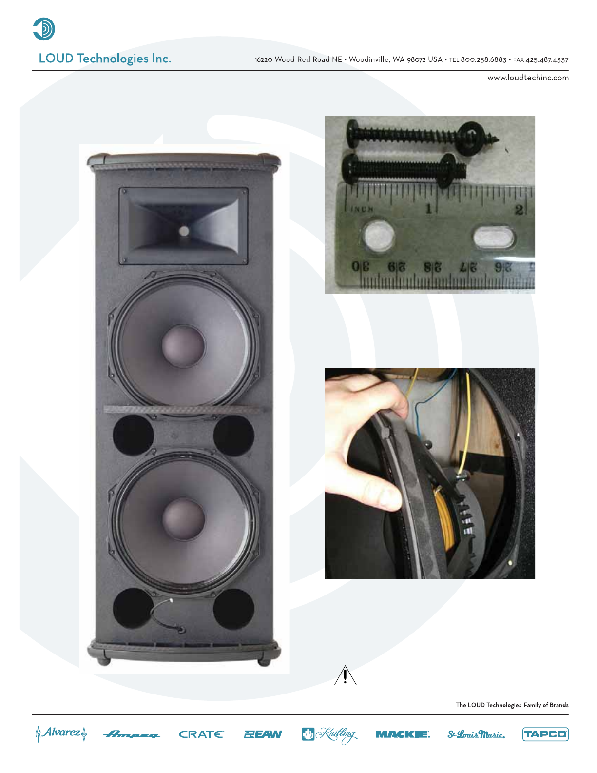
Carefully begin to remove the woofer.
4
in a safe place. Note: There are two
different screws that connect the woofer
to the cabinet.
A fl at head screwdriver may aid in
loosening the woofer by prying between
it and the cabinet. Hold the woofer
in place with one hand while prying
around the edge with your free hand.
Caution: The woofer is approximately
11 pounds with the weight unevenly
distributed.
Page 6

Bottom woofer replacement continued:
push down
-
+
6
The positive (solid yellow) and negative
5
The picture to the right shows what
6
(solid blue) cables are still attached to
the woofer terminals. Remove the cables
from their terminals simply by pushing
down on the terminal and pulling out the
cable.
the SR1522z looks like with the grill and
bottom woofer removed. Place the
new woofer (part #0013913) where the
old one was. Follow the same steps as
above, but backwards 5 to 1, making
sure to keep the led PCB assembly cable
in front of the woofer. Power up the
SR1522z and the new woofer should now
be pumping out glorious lows. Awesome,
you just replaced a 15” woofer!
Page 7

Follow steps 1-4 of the led PCB
1
Top woofer replacement:
replacement instructions, as the grill will
need to be removed in order to access
the top woofer.
7
screws 1-4
screws 5-8
5
1
4
8
6
Keep the eight screws and fl at washers
2
3
7
3
in a safe place. Note: There are two
different screws that connect the woofer
to the cabinet.
Eight screws and fl at washers need to
2*
be removed from the woofer using the
phillips head screwdriver.
The grill support (located just above
*
screws 7 and 8) does not need to be
taken off in order to remove and replace
the top woofer. However, it would
certainly make the repair slightly more
manageable. Directions for removing the
grill support may be found on page 9.
Page 8

Top woofer replacement continued:
8
Carefully begin to remove the woofer.
4
+
The positive (solid blue) and negative
5
A fl at head screwdriver may aid in
loosening the woofer by prying between
it and the cabinet. Hold the woofer
in place with one hand while prying
around the edge with your free hand.
Caution: The woofer is approximately
11 pounds with the weight unevenly
distributed.
-
Push down
(solid black) cables are still attached to
the woofer terminals. Remove the cables
from their terminals simply by pushing
down on the terminal and pulling out the
cable.
This is what the SR1522z looks like with
6
the grill and top woofer removed. Place
the new woofer (part #0013913) where
the old one was. Follow the same steps
as above, but backwards 5 to 1. Power
up the SR1522z and the new woofer
should now be pumping out glorious
lows. Awesome, you just replaced a 15”
woofer!
Page 9

Top woofer replacement continued:
The grill support (located just above
*
screws 7 and 8 and outlined below)
does not need to be taken off in order
to remove and replace the top woofer.
However, it would certainly make
the repair slightly more manageable.
Directions for removing the grill support
are as follows:
The grill support is covered with a
1
9
grill support
screw locations
rubber strip. The four screws may be
accessed by either: (1) peeling back
the rubber strip, or (2) puncturing a
hole through the rubber strip where
the screws are located with the phillips
head screwdriver. The grill support is
easily removed by pulling it off of the
cabinet. Don’t forget to screw the grill
support back in place once the woofer is
replaced!
4
8
7
3
Page 10

High Frequency Driver replacement:
Follow steps 1-4 of the led PCB
1
replacement instructions, as the grill will
need to be removed in order to access
the high frequency driver.
10
1
4
2
3
Keep the four screws and fl at washers in
3
a safe place.
Four screws and fl at washers need to be
2
removed from the horn using the 5mm
allen wrench.
Carefully begin to remove the entire
4
horn assembly (with the high frequency
driver still attached).
Caution: The horn weighs about 5
pounds, and the weight is unevenly
distributed.
Page 11

High Frequency Driver replacement continued:
+
-
Push down
The positive (solid blue) and negative
5
(blue and black) cables are still
attached to the high frequency driver
terminals. Remove the cables from their
terminals simply by pushing down on the
terminal and pulling out the cable.
11
This is what it looks like with the grill and
6
horn removed. See the next page
for further instructions and additional
pictures on how to remove and replace
the high frequency driver.
Page 12

High Frequency Driver replacement continued:
headless screw
nut
locking washer
fl at washer
12
Four nuts and eight washers may be
7
removed from the driver using the
8mm open end wrench. Turn counterclockwise to loosen and remove,
clockwise to tighten. The other three are
located around the horn assembly. Lift
the horn up as the nuts are loosened. It
cannot be removed otherwise. Notice
that the fl at washer is on the bottom,
followed by the locking washer, and
fi nally the nut.
Keep the four nuts, four locking washers,
8
The horn assembly should easily lift right
9
and four fl at washers in a safe place.
off of the high frequency driver.
Page 13

High Frequency Driver replacement continued:
13
1
4
2
3
Four headless screws need to be
10
removed from the high frequency driver.
Pliers could help if the screws are too
tight. Turn counter-clockwise to loosen
and remove, clockwise to tighten. Keep
the four headless screws in a safe place.
Place the new high frequency driver
(part #0008093) where the old one
was. Follow the same steps as above,
but backwards 10 to 1. Power up the
SR1522z and the new driver should now
be pumping out those highs again.
Fantastic, you just replaced a high
frequency driver!
Page 14

Diaphragm replacement:
At the present time (December 2006),
1
2
diaphragms are not currently available,
so you will have to replace the complete
driver following the previous section
(pages 10-13). If you have received
a diaphragm, please follow the steps
below.
Follow steps 1-5 of the high frequency
driver replacement instructions, as the
horn will need to be removed in order to
access the diaphragm.
14
The horn assembly is shown above with
3
1
4
the high frequency driver circled. Four
screws need to be removed from the
driver using the 3mm allen wrench.
2
3
Keep the four screws in a safe place.
4
The diaphragm and plate adapter are
5
easily removed from the horn assembly.
Page 15

Diaphragm replacement continued:
This is what the diaphragm (left) and
7
15
plate adapter (right) both look like. Place
the new diaphragm (part # coming
soon) where the old one was. Follow the
same steps as above, but backwards 6
to 1. Power up the SR1522z and the new
diaphragm should now be pumping
out those highs again. Sweet, you just
replaced a diaphragm!
This is what the plate adapter and
6
diaphragm look like after they have
been removed from the horn assembly.
The diaphragm is separated from the
plate adapter simply by pushing down
on the terminals.
Page 16

Amplifi er Assembly replacement:
16
14
13
12
1
2
3
4
Keep the fourteen screws in a safe
5
2
place.
11
10
Fourteen screws need to be removed
1
6
7
9
from the amplifi er assembly using the
phillips head screwdriver. The amplifi er
assembly is capped by two cover plates
outlined above.
8
The covers may be worked loose by
3
wedging a fl at head screwdriver in
between the cabinet and the cover, as
well as the amp assembly and cover.
Make sure to get around the entire cover
plate in order to liberate them.
Page 17

Amplifi er assembly replacement continued:
1
17
1
2
3
4
5
The amplifi er assembly is now ready to
5
be separated from the cabinet. Do not
completely take the amplifi er assembly
off yet, as fi ve cables need to be
removed fi rst (as shown above):
(1) led PCB cable, (2) blue and black,
(3) solid blue, (4) solid black, and (5)
solid yellow. Do not force cable removal
or connection, although needle-nose
pliers may aid in loosening the crimped
cables.
Caution: The amplifi er assembly is
approximately 18 pounds, so please
make sure to grasp it fi rmly.
2
Once the two cover plates are removed,
4
two more screws need to be taken out in
order to separate the amplifi er assembly
from the cabinet. Keep the two screws in
a safe place.
Page 18

Amplifi er assembly replacement continued:
18
Edge of
amplifi er
assembly
Edge of
amplifi er
assembly
1
1
Edge of amplifi er assembly
5
34
2
Closeups of the led PCB cable and
6
See the pictures to the right for the
7
connector are shown above. The black
wire of the cable is closest to the edge of
the amplifi er assembly. The cable only fi ts
in one way.
closeups of the woofer and high
frequency driver terminals. Make sure
the cables are reconnected to the same
terminals they were removed from (but
on the new amplifi er assembly). Once
again, they are: (2) blue and black, (3)
solid blue, (4) solid black, and (5) solid
yellow. Do not force cable removal
or connection, although needle-nose
pliers may aid in loosening the crimped
cables.
Edge of amplifi er assembly
5
4
3
2
Page 19

Amplifi er assembly replacement continued:
Place the new amplifi er assembly
8
(part #0014138-00) where the old one
was. Follow the same steps as above,
but backwards 7 to 1. Remove the
serial number from the faulty amplifi er
assembly (as shown in picture above)
and place on the new amplifi er
assembly. Power up the SR1522z and
relish in the fact that you just replaced
an amplifi er assembly. Hats off to you for
a job well done!
19
9
Important: The faulty amplifi er
assembly must be returned to LOUD
Technologies. The address should
be on the return shipping label that
was provided with the new amplifi er
assembly. If not, the return address is at
the top of this page. Also, please write
the order number and service request
number (ex: 1046256-1203935) in big,
black, bold numbers on the outside of
the box. This helps expedite the return.
 Loading...