

Page 1
Installing the SP-41R
The SP-41R can be installed in a double-gang
electrical box with a Decora®-style faceplate.
Connecting Multiple Remote
Controls
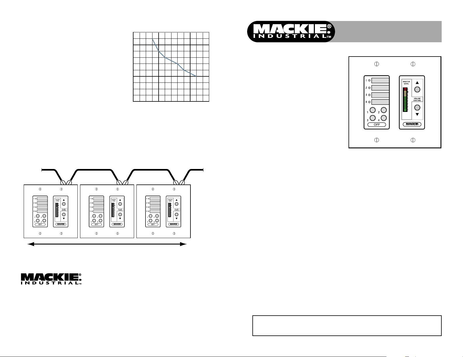
Up to ten remote controls can be connected
to the SP1200/SP2400 REMOTE bus. The
maximum length of the cable depends on the
type of cable used and the number of remote
controls used in the system.
As a general rule, using 22 gauge wire (at
0.014 Ω /ft. and 34 pF/ft.), one remote can
be up to 3000 feet away, five remotes can be
up to 2000 feet away, and ten remotes can be
up to 750 feet away before transmission
losses become a factor.
Feet of Cable versus
Maximum Number of SP-41R Remotes
10
9
8
7
6
5
4
3
2
Number of SP-41R Remotes
1
0
0
250
500
750
1000
1250
1500
1750
Feet of Cable
Distance Chart for SP-41R Cable
2000
2250
2500
2750
3000
The SP-41R is a real-time remote switch
and volume control for use with the SP1200
and SP2400 Program Controller/Amplifiers.
The SP-41R can be used to select the input
source and adjust the output volume for the
amplifier channel to which it is connected.
Up to ten remote controls can be connected
to the SP1200 or SP2400
REMOTE
connector.
SP-41R
Remote Switch and Volume Control
Quick-Start Guide
3
0
3
6
9
15
30
55
From SP1200/SP2400
3
0
3
6
9
15
30
55
3
0
3
6
9
15
30
55
Total Distance Dependent on Type of Cable Used
www.mackieindustrial.com
16220 Wood-Red Road NE, Woodinville, WA 98072 USA
TEL 888.337.7404, FAX 425.487.4337, EMAIL industrial@mackie.com
UK +44.1268.571.212, FAX +44.1268.570.809 +industrial@rcf-uk.com
ITALY +39.0522.354.111, FAX +39.0522.926.208 +industrial@rcf.it
FRANCE +33.3.8546.9160, FAX +33.3.8546.9161 +rcf.commercial@wanadoo.fr
GERMANY +49.2572.96042.0, FAX +49.2572.96042.10 +industrial@mackie.de
Part No. 910-222-20 Rev. B 1/02
© 2002 Mackie Industrial. All Rights Reserved. Printed in the USA.
To Next Remote
3
0
3
6
9
15
30
55
Safety First!
Before connecting and using the
equipment, please read this Quick-Start Guide
carefully and keep it for future reference.
WARNING! This equipment has been
designed to be installed by qualified
professionals only! There are many factors to
be considered when installing professional
sound reinforcement systems, including
mechanical and electrical considerations, as
well as acoustic coverage and performance.
Mackie Industrial strongly recommends that
this equipment be installed only by a
professional sound installer or contractor.
Please visit our website at www.mackieindustrial.com for updates
and more information on this and other Mackie Industrial products.
1. Never install, connect, or disconnect the
remote control with the SP1200/SP2400
power supply on.
2. Before applying power to the SP-41R, make
sure the wiring is correct as described in
this Quick-Start Guide.
Page 2
J2
1
2
3
REMOTE
SP1200/SP2400
REMOTE
J2
SP-41R
GROUND
DATA +
DATA –
DATA –
3
0
3
6
9
15
30
55
GROUND
DATA +
SP-41R
REAR VIEW
Front Panel Features
SELECT BUTTONS
Use to select the input source for the
SP1200 or SP2400. These buttons
correspond to the buttons on the front
panel of the SP1200/SP2400. The OFF
button deselects Inputs 1-4 and activates
the MIC/LINE input.
Due to the cross-fade that occurs when
switching input sources, there may be a
few seconds delay when attempting to
switch quickly between sources.
SELECT LED INDICATORS
Indicates the active input source. When
the LED is lit, the corresponding input
source is selected. When all the LEDs are
off, the OFF button is active and the MIC/
LINE input is selected.
Rear Panel Features
A space is provided next to each
indicating LED for inserting a 1/4" x 7/8"
label to identify the input source assigned
to each select button.
UP/DOWN VOLUME CONTROL
Use to adjust the output level for the
zone. Duplicates the function of the
MASTER VOLUME buttons on the SP1200/
SP2400 front panel.
LED DISPLAY
Indicates the level setting of the MASTER
VOLUME control.
Note: The LED display does not indicate the
signal level in real time, but rather the level
setting of the MASTER VOLUME control.
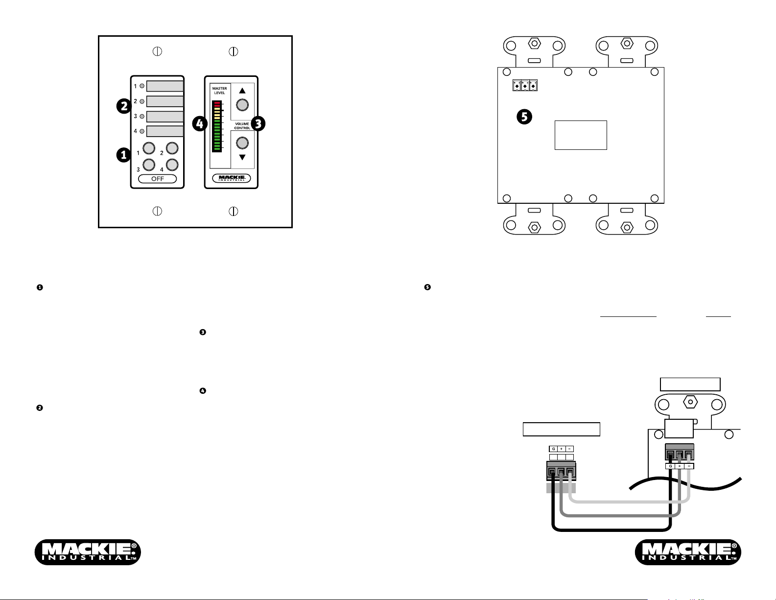
CONNECTOR (J2)
Connect the wires from the SP1200 or
SP2400 REMOTE bus to this connector on
the back of the SP-41R using the supplied
Phoenix-type connector. Strip the wire
back about 1/4", insert the wire as far as
it will go into the connector and tighten
down the screw with a small slot-head
screwdriver.
Use a high-quality three-conductor
shielded cable to make this connection,
such as Belden 8451, 9451, or equivalent.
The connector is wired as follows:
SP1200/SP2400 SP-41R
1 (Ground) GND
2 (+ Data with +24V DC power) +
3 (– Data with +24V DC power) –
 Loading...