

Mackie SP400C User Manual
SP400C
2-Way Ceiling Monitor
Instruction Manual
30
15
15
7.5
30
100v
7.5
3.7
70v
FULL
RANGE
(16 OHMS)
FULL
RANGE
HIGH
PASS
Sound Palette
1. Safety Instructions
1.1. Read Instructions — Before connecting and using
the equipment, please read this Instruction Manual
carefully and keep it for future reference.
1.2. HEED ALL WARNINGS — Always follow the
precautions provided on this Mackie Designs product
and in the instruction manual.
1.3. Water and Humidity — Do not use this Mackie
Designs product near water; for example, in the
vicinity of a bath tub or sink, in a damp cellar, near a
swimming pool, etc.
1.4. Foreign Bodies and Liquids — Be careful not to
allow any foreign bodies or liquids to get into this
Mackie Designs product.
1.5. Servicing — The user should never attempt to
make any repairs on this Mackie Designs product
unless otherwise indicated in the instruction manual.
All repairs should be made by qualified service
technicians.
1.6. Installation — Do not install this Mackie Designs
product in any way that is not provided for in the
instruction manual.
1.7. Respect the Safety Standards — The entire sound
system must be designed in compliance with the
current standards and laws regarding electrical
systems.
1.8. Specifications — When installing and using this
Mackie Designs product, keep in mind the technical
specifications indicated in the dedicated section of
the manual.
1.9. Accessories — Install and use this Mackie
Designs product only with the accessories specified
by the manufacturer or supplied with the product.
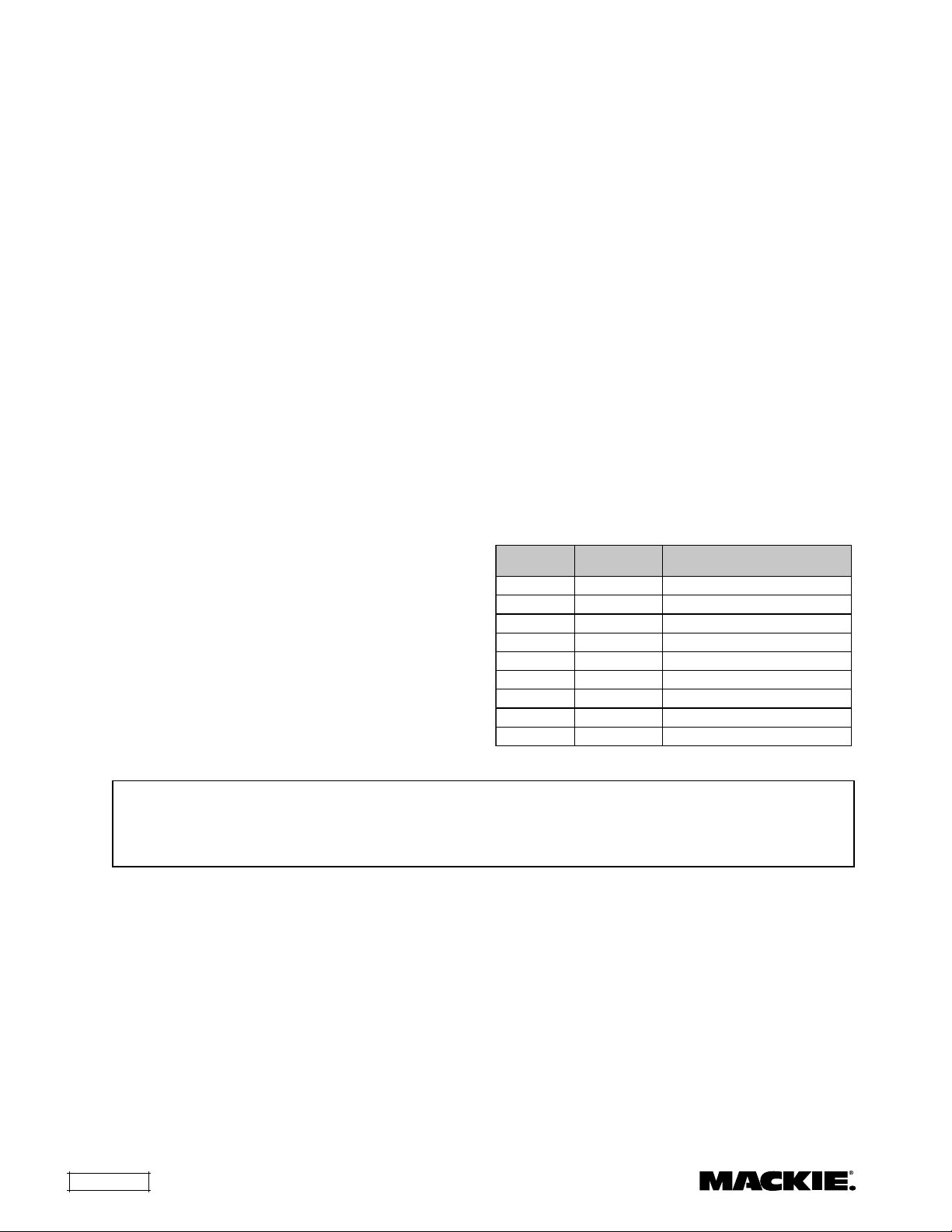
1.10. Hearing Loss — Exposure to high sound levels
can cause permanent hearing loss. The sound
pressure level which leads to hearing loss varies
considerably from one person to another, and
depends on the duration of exposure. The U.S.
Government’s Occupational Safety and Health
Administration (OSHA) has established the maximum
sound pressure levels that can be with stood without
causing damage, which are shown in the table below.
According to the OSHA regulations, any exposure over
the maximum limits indicated in the table can reduce
the hearing capacity of a person. To prevent
potentially dangerous exposure to high sound
pressure levels, anyone subjected to such levels must
use suitable protection. When a Mackie Designs
product capable of producing high sound levels is
being used, it is therefore necessary to wear ear plugs
or protective earphones when the limits shown in the
table are exceeded.
Consult the specifications provided in the instruction
manual to know the maximum sound pressure (SPL)
the speaker is capable of producing.
repnoitaruD
)sruoh(yad
809bulcllamsaniouD
629
459niartyawbuS
379
2001cisumlacissalcduolyreV
5.1201
1501teef05taevitomocoL
5.0011
sselro52.0511trecnockcoratastraptseduoL
leveldnuoS
)ABd(
elpmaxelacipyT
WARNING! This equipment has been designed to be installed by qualified professionals only! There are
many factors to be considered when installing professional sound reinforcement systems, including
mechanical and electrical considerations, as well as acoustic coverage and performance. Mackie Designs
strongly recommends that this equipment be installed only by a professional sound installer or contractor.
2. Table of Contents
1. SAFETY INSTRUCTIONS ....................................................... 2
2. TABLE OF CONTENTS............................................................ 2
3. KEY FEATURES ....................................................................... 2
4. INTRODUCTION ...................................................................... 3
5. PRODUCT DESCRIPTION ....................................................... 3
6. INSTALLING THE SP400C ...................................................... 4
7. SPECIFICATIONS .................................................................... 6
8. SERVICE INFORMATION........................................................ 8
Part No. 0001875 Rev. A 03/03
© 2003 Mackie Designs Inc. All Rights Reserved.
SP400C – 2
3. Key Features
• Proprietary waveguide design to improve hi-frequency dispersion
• Ported design for extended low-frequency response
• 1" soft-dome tweeter with neodymium magnetic motor structure
• 6.5" low-frequency woofer
• Built-in 70/100V transformer with multiple taps
• Transformer bypass for low-impedance operation (16 ohms)
• True 2-way crossover
• Built-in switchable high-pass filter
• Complete assembly for quick installation
• UL/cUL/CE listed
4. Introduction
5. Product Description
The SP400C is a complete two-way bass-reflex
flush-mount loudspeaker assembly designed for
ease of installation, extremely wide coverage, and
high-fidelity full-range sound reinforcement.
The SP400C is ideal for use in business music
systems and foreground/background music applications.
Installing the SP400C is simple. The one-piece
assembly includes the backcan, mounting tabs
(clamps), front baffle rim, high- and low-frequency
drivers, and our proprietary two-way waveguide based
on Mackie Designs award-winning HR824 studio
monitors. Support rails are supplied that attach to
the C-ring (included) and distribute the speaker’s
weight to the ceiling tile T-channels. A template is
also included for marking the correct cutout size.
The Phoenix-style connector on the back of the
assembly provides input and loop-through
connections for 70V/100V distribution systems, or
low-impedance operation. An easily accessible
rotary switch on the front panel selects the
appropriate tap (from 3.7 watts to 30 watts). A
second switch allows you to select among full-range
operation, high-pass (when used with a subwoofer),
and full-range low-impedance operation (16 ohms).
A plastic paint shield is provided that protects
the transducers so the front baffle rim and grille can
be painted to match the surrounding décor.
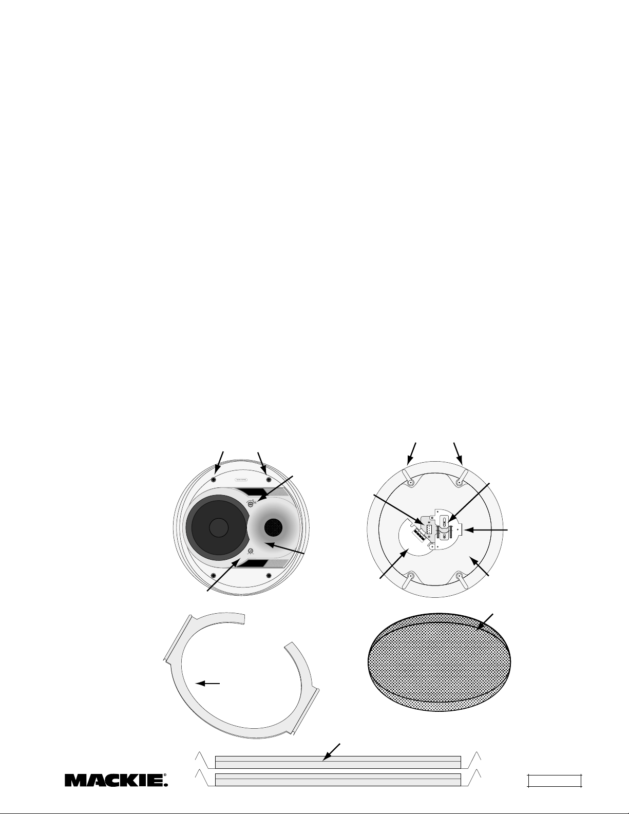
1. Grille
2. C-Ring
3. Support Rails
4. Mounting Tabs
5. Attachment Screws
6. Backcan
7. Terminal Cover Plate
8. Connector
9. Strain Relief
10. Seismic Safety Tab
11. Waveguide
12. Tap Selector Switch
13. Full-range/High-Pass Selector Switch
5. Attachment
13. Full-Range/High-Pass
Selector Switch
Screws
30
15
15
7.5
30
100v
7.5
3.7
70v
FULL
FULL
RANGE
RANGE
HIGH
(16 OHMS)
PASS
2. C-Ring
12. Tap Selector
Switch
8. Connector
11. Waveguide
7. Terminal
Cover Plate
4. Mounting
Tabs
1
+
LOOP
2
THRU
+–
IN IN
3
4
–
LOOP
THRU
9. Strain Relief
10. Seismic
Safety Tab
6. Backcan
1. Grille
3. Support Rails
SP400C – 3
 Loading...