

Page 1
A P PLI C A T I O N S
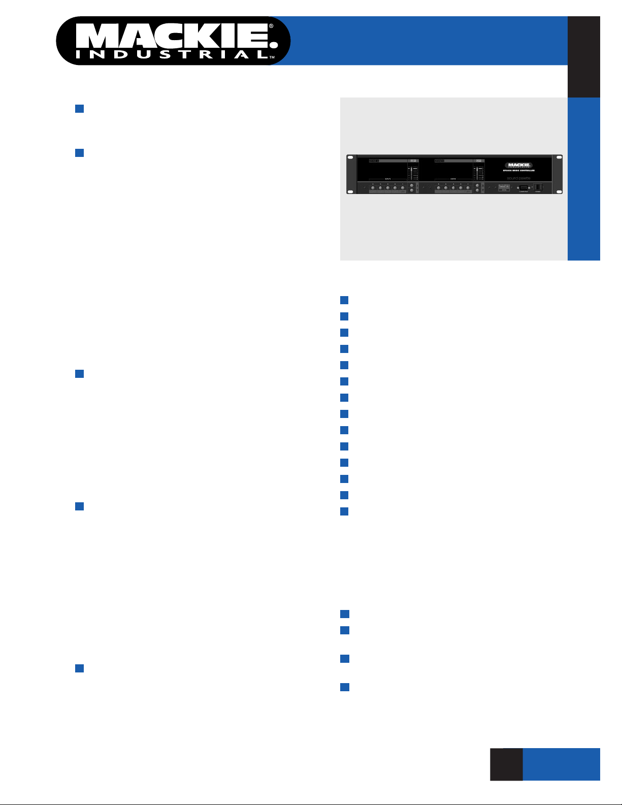
SP2400
SOUND PALETTE® Series
The SP2400 is a dual-channel music controller
and amplier designed for installations requiring
high performance, exible features and ease of use.
Four independent stereo, line level inputs are
provided for connection of standard music sources,
such as CD, Tape, Satellite Receiver, etc. Each input
is terminated to dual RCA connectors. An integral
AGC circuit automatically compensates for level differences between input sources. A three band EQ,
with sweepable mid-range control is provided for
equalization of the music sources. In addition, an
internal option slot accepts specic EQ modules
designed to enhance the response of various speaker
systems. A dynamic loudness circuit boosts bass
response at low volume levels, to ensure proper
tonal balance. Music Input 1 is buffered to a stereo
RCA output that may be used for music-on-hold or
other external applications.
One input is provided for a paging microphone,
and is terminated to both removable Phoenix-type
and XLR connectors. Two band EQ, variable gain and
switchable phantom power are provided. A variable
VOX sensitivity control allows precise setting of trigger threshold points. Page Mic activation and music
ducking can also be activated by using the supplied
contact terminals. An optional noise-sensing microphone can be used.
A second microphone input, per channel, is provided for voice reinforcement. This input is terminated to a Phoenix-type connector and offers two
band EQ, variable gain and switchable phantom
power. The gain of this input is independent of the
master levels set for the music sources, and is
adjustable by the master volume control when all
music sources are off. Settings of the microphone
and music levels are retained in memory, allowing
adjustment of one source without affecting the
other.
Operator controls provide four music source
selector buttons and one OFF button for each channel. LED ladder display indicates relative level setting. Push buttons are provided for volume UP and
DOWN. All control setting changes can be made from
continued on last page
Two Channel Controller/Amplier
Features
Two channel controller/amplier
4 stereo, line-level program inputs
1 Mic input per channel
1 Paging Mic input
Digital cross-fade between Input sources
200 watts/channel at 70V/100V or 8Ω
Transformerless amplier outputs
Ambient noise sensing for page mic
AGC for music sources
3-band sweepable EQ for music sources
2-band EQ on each mic input
Expandable to 16 zones
Dual-zone or stereo operation
RS485 port for third-party control systems
Zoned Music Distribution
Multi-Zone Paging with
Program Distribution
Automated Noise-Compensating
Gain Systems
Music/Speech Reinforcement Systems
1
O F 6 P A G E S
AMPLIFIER
SP2400
Page 2

SP2400
Two Channel Controller/Amplier
AMPLIFIER
Specications
Inputs
Program Inputs: 4 Stereo RCA, –10dB to +10dB
Mic 1: Balanced, 100Ω, –52 to +4 dB,
variable, switchable phantom power,
XLR and Phoenix-type terminals
SP2400
Mic 2: Balanced, 100Ω, –52 to +4 dB,
variable, switchable phantom
power, Phoenix-type terminals
Amp In: –10dB, Unbalanced, RCA
Outputs
Amplier Channels: Dual Mono, or
Stereo operation
Output Power, per channel: 200 Watts, 20Hz–20KHz
Auxiliary Output: Unbalanced, RCA stereo
or dual mono
Pre-Out: –10 dB, Unbalanced, RCA
Controls
Program Select: 4 Momentary Pushbuttons
with LED indicators
Volume UP/DN: 2 Momentary Pushbuttons
Music OFF/Mic 2 Select: 1 Momentary Pushbutton
with LED Indicator
Mic 1 EQ: Low/High Potentiometers
(100 to 12kHz ±12dB)
Mic 2 EQ: Low/High Potentiometers
(100 to 12kHz ±12dB)
Program EQ: Low/Mid/Mid Sweep/
High Potentiometers
(80–12kHz ±12dB)
Phantom Power Select: 4 DIP switches (+24 VDC)
Mic Input Pad: –20 dB, on 4 DIP Switches
Page Mic Activation: 2-pole contact on
Phoenix-type connector
VOX Sensitivity: Potentiometer
Physical
Construction: Black painted aluminum and steel
chassis, White nomenclature
Enclosure: 19" Rack Mountable,
3.5" panel space
Dimensions (HxWxD): 3.5" x 19" x 16.63"
(88.8mm x 482.6mm x 422.3mm)
Net Weight: 34 lbs. (15.42kg)
Accessories
SP-NSM: Ambient Noise Sensing Microphone
SP-SW4: Remote program selection
SP-RVC: Remote volume control
Indicators
Program Select: 4 Indicator LEDs per Channel, Plus OFF
Volume Setting: 8-segment LED Bar Graph
Status: Power, Overload, Protection
Performance
Frequency Response: 20Hz – 20 kHz, +/–0.5 dB
Total Harmonic Distortion: Less than 0.01% at 200W
Signal to Noise Ratio: Greater than 90dB
2
O F 6 P A G E S
2
O F 6 P A G E S
Page 3

SP2400
1 2 3 4 5 6 7 8
1 2 3 4
1 2 3 4 5 6 7 8
SP2400
MUSIC CONTROLLER
EXPANSION IN EXPANSION OUT
THE FOLLOWING ARE TRADEMARKS OR REGISTERED TRADEMARKS OF MACKIE DESIGNS INC
"MACKIE.","MACKIE INDUSTRIAL", AND THE "RUNNING MAN" FIGURE. COPYRIGHT ©1999 ALL RIGHTS RESERVED
AMP ADDRESS RS485 REMOTE
ZONE A
+
–
OUTPUT
100/70V/8
230/115V 50/60 Hz FUSE 115/T8A
DIRECT
L
R
OUTPUT
CAUTION: TO REDUCE THE RISK OF FIRE
REPLACE WITH SAME TYPE FUSE AND RATING
0
I
HIGH 12kFREQMIDLOW 80Hz
PROGRAM EQ
U
+12-12
U
+12-12
U
+12-12
1K
3K
400
8k
250
PHANTOM
U
+12-12
U
+12-12
+
-
PAGING
MIC
VOX
+
-
GAIN +20dB
AMBIENT
MIC
GAIN LOW HIGH
MIC/LINE INPUT B
AMP ADDRESS RS485 REMOTE
AMP IN
ZONE B
+
–
OUTPUT
100/70V/8
1
2
3
G
+
–
0
I
PRE OUT
G
+
–
1 2 3 4 5 6 7 8 1 2 3 4
LOCAL
1 2 3 4
REMOTE
1 2 3 4
STEREO
MONO
CONCEIVED, DESIGNED, AND MANUFACTURED BY MACKIE DESIGNS INC. • WOODINVILLE • WA • MADE IN USA • FABRIQUE AU USA
A
G
B
A
G
SERIAL NUMBER
Two Channel Controller/Amplier
3
O F 6 P A G E S
Page 4

SP2400 Two Channel Controller/Amplier
ON
1 2 3 4
1 2 3 4
U
+12-12
U
+12-12
PARALLEL
INPUTS
+
-
G
+
–
CONTROL
ZONE A
ZONE B
0
I
ALL CALL
GROUND
HIGH 12kFREQMIDLOW 80Hz
PROGRAM EQ
U
+12-12
U
+12-12
U
+12-12
1K
3K
400
8k
250
PHANTOM
U
+12-12
U
+12-12
+
-
PAGING
MIC
VOX
+
-
GAIN +20dB
GAIN +20dBPHANTOM
AMBIENT
MIC
GAIN LOW HIGH
MIC/LINE INPUT A
AMP IN
–
1
2
3
G
+
–
HIGHLOW
GAIN
DIRECT
L
R
OUTPUT
PROGRAM INPUTS
PAGING MIC
1 2 3 4
PRIORITY
PRE OUT
G
+
–
A
G
B
4
O F 6 P A G E S
Page 5

SP2400
Architects’ & Engineers’ Specications
The background music/paging processor shall
have UL, C-UL and CE safety certications and be
a dual zone unit that is expandable up to a total
of 16 zones by adding up to seven additional units
(SP1200/SP2400) that can be either single or dual
zone processors. It shall consist of the following subsystems: (1) 4 stereo line level inputs, (2) 3 microphone inputs, one paging, one sound reinforcement
and one ambient noise sensing,(3) a 3-band equalizer per zone for the line level inputs, (4) a 2-band
equalizer, per zone, for the paging and sound reinforcement microphone inputs, (5) a transformerless
200W power amplier, per zone, that will accept
plug-in loudspeaker equalization modules, 70/100V
or 8Ω operation, (6) two auxiliary power amplier
inputs, per zone, (7) a signal processing and two line
level outputs, per zone, (8) connectors and circuitry
for remote control of level, program selection and
paging microphone priority, (9) an expansion bus to
carry balanced audio and control data to other units
in a multi-processor system, (10) an internal RS485
port to re-ash the unit’s rmware.
The four line-level stereo inputs shall be unbalanced, terminated to RCA connectors and accept
nominal -10dB signals. The stereo input signals
shall be internally mixed to mono and remain available to the expansion bus in stereo. Selection of
the active input shall be from either a momentary
push button on the front panel or remotely from an
optional accessory panel provided by the manufacturer. The selected input shall allow cross fading
with the current program. When the paging microphone is activated, the current line level program
shall attenuate to a level that is preset by a trim
control on the rear panel. A dip switch shall be
provided to direct the line level input signals to
other units in a multi-processor system via the
expansion bus.
The paging microphone input, per zone, shall be
actively balanced, accept a nominal signal between
–52dB and +4dB that is trimmed by means of a dip
switch on the rear panel. It shall be terminated in
a XLR connector that is parallel to a Phoenix-type
Two Channel Controller/Amplier
connector. The input shall provide 24VDC phantom
powering that is selected by a dip switch on the rear
panel. The input shall be activated by either VOX or
a contact closure made at a connector on the rear
panel. The VOX level shall be set by a potentiometer
on the rear panel. A dip switch shall be provided
on the rear panel to direct the paging microphone
signal to other units in a multi-processor system via
the expansion bus.
The sound reinforcement microphone input, per
zone, shall be actively balanced, accept a nominal
signal between –52dB and +4dB that is trimmed by
means of a dip switch on the rear panel. It shall be
terminated in a XLR connector that is parallel to a
Phoenix-type connector. The input shall provide 24V
phantom powering that is selected by a dip switch
on the rear panel. The input shall be activated by
a momentary switch on the front panel, an optional
remote control panel supplied by the manufacturer,
or a contact closure made at a connector on the rear
panel. A dip switch shall be provided on the rear
panel to direct the sound reinforcement microphone
signal to other units in a multi-processor system via
the expansion bus.
The ambient noise sensing microphone input, per
zone, shall be actively balanced; and accept a nominal signal between –52dB and +4dB that is trimmed
by means of a dip switch on the rear panel. It shall
be terminated in a Phoenix-type connector. The input
shall provide 24V phantom powering that is selected
by a dip switch on the rear panel. An optional ambient
noise sensing microphone shall be available from the
manufacturer as an accessory.
Two-band equalization for the paging and sound
reinforcement microphones and three-band equalization for the line level inputs per zone shall be
provided. All adjustments shall be made by potentiometers on the rear panel. The two-band equalizers shall have shelving lters at 100Hz and 10kHz
that can be adjusted ±12dB. The three-band equalizer, for the stereo line level inputs, shall have
shelving lters at 80Hz and 12kHz that can be
adjusted ±12dB and a ±12dB mid-band lter that is
sweepable between 250Hz and 8kHz.
(continued on page 6)
O F 6 P A G E S
5
Page 6

AMPLIFIER
SP2400
SP2400
Architects’ & Engineers’ Specs (continued)
The integrated power amplier, per zone, shall be
capable of accepting equalization modules that will
optimize various loudspeakers offered by the unit’s
manufacturer. It shall produce a minimum of 200W
RMS over a range of 20Hz to 20kHz with no more
than 0.03% distortion and drive either 70/100V constant voltage lines or a constant impedance load of
8Ω , without having an output transformer. It shall be
protected from short circuit, overload conditions and
extreme operating temperatures. Two direct, unbalanced line level inputs to the amplier per zone shall
be provided via RCA connectors on the rear panel.
An expansion bus shall be provided to send and
receive balanced audio signals and control signals
to other units in a multi-processor system over distances up to 2500 ft. on 25 conductor, shielded
cable or industry standard computer cables terminated with DB25 male connectors. Complete setup
control of a multi-processor system shall be possible
through the dip switch settings on the individual
units and without an external processor. An internal
industry standard RS232 port shall be included to reash the unit’s rmware using software provided by
the manufacturer.
The power supply shall be internal and connected
to 50 or 60Hz source current through a detachable
IEC power cord. It shall have an on/off switch, fuse
holder. The power supply shall draw a maximum of
5A and illuminate an indicator light when on.
The unit shall be self-contained in an aluminum
and steel chassis that can be mounted in a standard
19" EIA rack using no more than 3.5" of vertical
space. The background music/paging processor
shall be a model SP2400 manufactured by Mackie
Industrial.
Two Channel Controller/Amplier
(continued from page 1)
optional remote controls. A three-wire remote control bus allows connection of up to 10 addressable
remotes on one pair of shielded microphone cable.
Each remote can be set to control either of the two
channels.
The output section of the SP2400 offers two discrete ampliers, each delivering 200 watts of RMS
power into either 70/100Volt line or into 8Ω loads.
The transformerless design of the ampliers allows
frequency response to 20Hz, without the distortion
and losses typical of conventional designs. The two
ampliers may be operated independently as two
zones, or as one stereo amplier.
All of the SP2400’s functions are under microprocessor control and management. An RS485 port
is provided on the rear panel to allow interconnection with industry-standard control systems. Up to
eight SP2400 units may be interconnected, to share
four music sources and control data.
This Mackie Industrial product is covered by an
exclusive, one-time NO FAULT repair policy in addition to a three-year limited warranty.
Electronic les for this product available at:
www.mackieindustrial.com
This Specication Sheet SP2400.PDF
Architects’ & Engineers’
Specications SP2400AE.TXT
Quick-Start Manual SP2400QS.PDF
Owner/Operator’s Manual SP2400ML.PDF
CADD les SP2400.DXF
EASE data SP2400.EAS
www.mackieindustrial.com
16220 Wood-Red Rd NE, Woodinville, WA 98072 USA
888.337.7404, fax 425.487.4337, industrial@mackie. com
UK + 44 1268 570 808, fax + 44 1268 570 809, industrial@rcf-uk.com
ITALY +39 0522 354 111, fax +39 0522 332 294, industrial@rcf.it
FRANCE +33 3 8546 9160, fax +33 3 8546 9161, industrial@rcf.fr
GERMANY +49 2572 96042 0, fax +49 2572 96042 10, industrial@mackie.de
Mackie Designs continually engages in research related to product improvement. New material,
production methods, and design renements are introduced into existing products without notice
as a routine expression of that philosophy. For this reason, any current Mackie Industrial product
may differ in some respect from its published description, but will always equal or exceed the
original design specications unless otherwise stated. ©1999-2000 Mackie Designs Inc. All
rights Reserved. and are registered trademarks of Mackie Designs Inc. Mackie
Industrial is a trademark of Mackie Designs Inc.
part no. 910-160-10
O F 6 P A G E S
6
 Loading...