

Mackie Sound Palette Series SP1200, Sound Palette Series SP2400, SP-DSP1 Specifications
SP-DSP1
DSP
SOUND PALETTE® Series
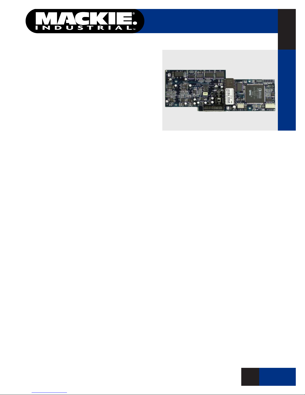
The Mackie Industrial SP-DSP1 is a real-time digital
signal processor that can be installed in the SP1200 or
SP2400. It uses a proprietary algorithm (patent pending) and adaptive digital ltering to sense noise in
a room with an ambient microphone and adjust the
gain of the program source accordingly. This unique
approach effectively "nulls out" the music sensed at
the ambient microphone, allowing the DSP to measure
the actual ambient noise level in the room. As the
ambient noise level of the room changes, the gain of
the program material automatically adjusts to compensate for those changes.
The SP-DSP1 is designed to be controlled with the
SP-Control™ application running under the Palm™ OS.
The SP-Control application is included on a 3.5" oppy
disk, and it can also be downloaded from the Mackie
Industrial website (www.mackieindustrial.com).
Once installed, the SP-DSP1 attenuates the signal by
up to 40 dB, depending on the setting of the Minimum
Gain control. This determines the lowest level to which
the SP-DSP1 can attenuate the program signal.
The Gain Range control determines the amount of
gain change allowed by the Automatic Level Control.
Add this number to the Minimum Gain setting to determine the maximum gain allowable.
The Noise Threshold control determines the point
at which the Automatic Level Control begins working.
When the ambient noise level crosses this threshold,
the DSP-1 begins to increase the program signal.
The Noise Range control works in conjunction with
the Gain Range control. The ratio of the two settings
determines how much the program level changes as a
function of the change in ambient noise level. For example,
if the Noise Range is set to 20 dB and the Gain Range
is set to 30 dB, then a 20 dB change in noise level
causes a 30 dB change in program level (a 2:3 ratio).
The Attack Time setting determines the rate at which
the program level increases. The higher the Attack
Time setting, the faster the program level increases
once the noise level crosses the Noise Threshold.
The Release Time setting determines the rate at which
the program level decreases. The higher the Release
Time setting, the faster the program level decreases
once the noise level drops below the Noise Threshold.
The SP-DSP1 can store up to ten preset congura-
tions for various functions or applications.
The Auto Calibration procedure computes the Room
Transfer Function (RTF) and prevents runaway gain.
Automatic Level Control for the SP1200/SP2400
Features
Adds ambient noise sensing capability to the SP1200
and SP2400 Program Controller/Amplier
Adaptive digital ltering analyzes the signal at the
ambient microphone and determines the amount of
ambient noise in a room
Automatically adjusts the system gain according to the
ambient noise level
SP-Control™ Palm™ OS application included for
remote control
Adjustable parameters on the Palm™ include minimum
gain, gain range, noise threshold, noise range, attack
time, and release time
Bargraph metering on the Palm™ monitors program
input level, microphone input level, program gain, and
program output level
Auto-calibration function
Upload and download capability from EEPROM to
SP-Control application
Zoned Music Distribution
Automated Noise-Compensating
Gain Systems
Multizone Paging/Background Music and
Speech Reinforcement Systems
SP-DSP1
A P PL IC AT I O N S
O F 2 P A G E S
1
o F 6 P A GE S
SP-DSP1
Automatic Level Control for the SP1200/SP2400
DSP
SP-DSP1
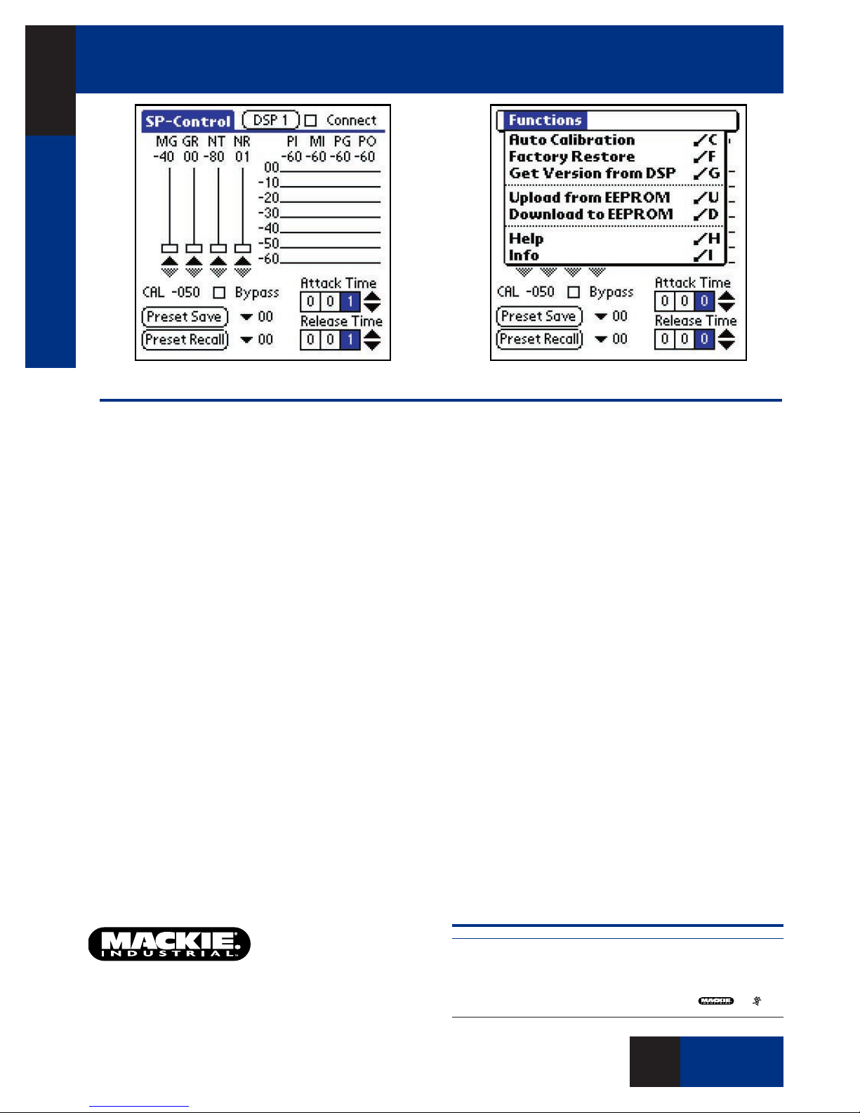
Screen Shots of SP-Control Palm™ Application
Architects’ and Engineers’ Specications
The SP-DSP1 shall consist of a DSP card and a power sup-
ply expansion card designed to be installed in the SP1200
and SP2400 Program Controller/Amplier. It shall provide
automatic level control for the program signal, dependent on
the ambient noise level. It shall use a proprietary ambient
noise level sensor algorithm derived from a Normalized Least
Mean Square Adaptive Filter (nLMS).
The SP-Control software shall provide a user interface and
provide control over the digital signal processing parameters
in the SP-DSP1, consisting of the following:
A Minimum Gain control shall provide a gain range from
–40 dB to 0 dB. The Minimum Gain setting shall determine
the normal operating level of the system prior to the action of
the Automatic Level Control.
A Gain Range control shall have a gain range from 0 dB
to +40 dB. The Gain Range setting shall determine the maximum level of the system after the Automatic Level Control
has been activated.
A Noise Threshold control
from –80 dB to 0 dB
mine the noise level above which the Automatic Level Control
begins to operate.
A Noise Range control shall provide a noise range from
+1 dB to +60 dB. The Noise Range setting shall determine
the rate the program level gain changes as a function of the
change in ambient noise level determined by the ambient
noise sensor algorithm.
. The Noise Threshold setting shall deter-
shall provide a Threshold range
An Attack Time setting shall provide an attack time range
from 1 second to 300 seconds
determine the time for the program gain to increase by 40 dB.
A Release Time setting shall provide a release time range
from 1 second to 300 seconds
determine the time for the program gain to decrease by 40 dB.
A Program Input Meter shall indicate the input level to the
SP-DSP1 with a range from –60 dB to 0 dB.
A Microphone Input meter shall indicate the ambient
microphone input level to the SP-DSP1 with a range from –60
dB to 0 dB.
A Program Gain meter shall indicate the amount of gain
the algorithm applies to the program input with a range from
–60 dB to 0 dB.
A Program Output meter shall indicate the output level
from the SP-DSP1 with a range from –60 dB to 0 dB.
The SP-DSP1 shall have memory allocated in EEPROM to
store up to ten presets for the adjustable DSP parameters
An Auto Calibration function shall be provided to compute
the coefcients for the Room Transfer Function (RTF), and optimize the algorithm to reject the music signal and more accurately measure the ambient noise.
The Automatic Level Control shall be a model SP-DSP1
manufactured by Mackie Industrial.
. The Attack Time setting shall
. The Release Time setting shall
.
Electronic les for this product available at:
www.mackieindustrial.com
This Specication Sheet SPDSP1.PDF
www.mackieindustrial.com
16220 Wood-Red Rd. NE, Woodinville, WA 98072 USA
888.337.7404, fax 425.487.4337, industrial@mackie.com
UK +44.1268.571.212, fax +44.1268.570.809, info@rcf-uk.com
ITALY +39.0522.354.111, fax +39.0522.926.208, industrial@rcf.it
FRANCE +33.3.8546.9160, fax +33.3.8546.9161, rcf.commercial@wanadoo.fr
GERMANY +49.2572.96042.0, fax +49.2572.96042.10, industrial@mackie.de
Mackie Designs continually engages in research related to product improvement. New material, production methods, and design renements are introduced into existing products without notice as a routine
expression of that philosophy. For this reason, any current Mackie Industrial product may differ in some
respect from its published description, but will always equal or exceed the original design specications
unless otherwise stated. ©2002 Mackie Designs Inc. All rights Reserved. and are
registered trademarks of Mackie Designs Inc. Mackie Industrial is a trademark of Mackie Designs Inc.
Part No. 0000759 Rev. A
O F 6 P A G E S
O F 2 P A G E S
o F 6 P A GE S
6
2
o F 6 P A GE S
 Loading...