

Page 1
Serial•9Serial•9
Serial•9
Serial•9Serial•9
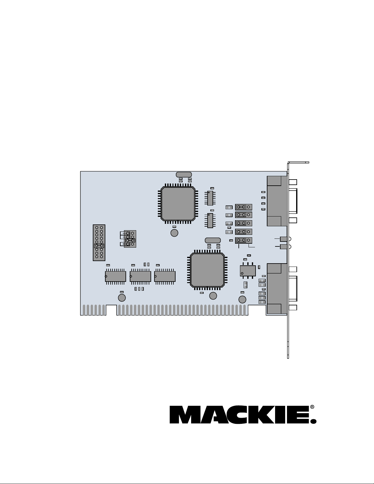
Installation Guide
for the HDR24/96
Serial 9 Pin Card
IRQ
IRQ2/9
IRQ3
IRQ4
IRQ5
IRQ7
IRQ10
IRQ11
IRQ12
IRQ15
JB2
C4
U2
I/O BASE
ADDRESS
JB1
C5
U3
C22
C21
+
BASE4
BASE5
BASE6
BASE8
R5 R4 R3
R1 R2
C3
U1
C23
C18
Y2
C16
R13
C17
R12
C20
U8
C19
U7
U5
+
C8
R8
L7
L4
L6
R15
L5
Y1
R14
C7
R6
DEVICE
U6
D1
C24
U4
+
C6
+
JP2
C11
C2
C1
C13
C15
C12
C14
JP3
JP4
JP5
JP1
CONTROLLER
R11
R9
L1
R7
C10
R10
L2
L3
J2
DEVICE
J1
C9
D2
+
+
D3
Dual Communication Card for the HDR24/96
Page 2
Important Safety Instructions
1. Read instuctions — Read, understand and follow all safety and
operating instructions before using this Mackie product.
2. Retain Instructions — Keep these safety and operating
Serial•9
instructions for future reference.
3. Heed Warnings — Follow all warnings on this Mackie product
and in these operating instructions.
4. Disconnect the power source to the HDR24/96 before installing
the Serial•9 Card.
5. Servicing — Do not attempt to service this Mackie product. All
servicing should be referred to the Mackie Service Department.
Introduction
Thank you for choosing Mackie Designs for your
hard disk recording solution. The Serial•9 is a major
step forward in our continued support of the
HDR24/96 Hard Disk Recorder.
The Serial•9 replaces the existing MIDI card in
the HDR24/96, and offers both MIDI (MTC and
MMC) and Sony 9-Pin communication with external
devices like remote controllers and DAWs (Digital
Audio Workstations).
No additional setup is required. Just plug the
Serial•9 in and you’re ready to go!
ATTENTION: The installation of this option requires opening the
HDR24/96 and handling sensitive electronic components. Anti-static
must
precautions
be taken in order to prevent potential damage to
the unit. Damage caused to the unit due to improper installation or
handling of these components
will not be covered under warranty
If you do not feel capable of performing this installation, please
call Mackie Tech Support at 800-898-3211 to obtain a referral to
a service center that can perform the installation.
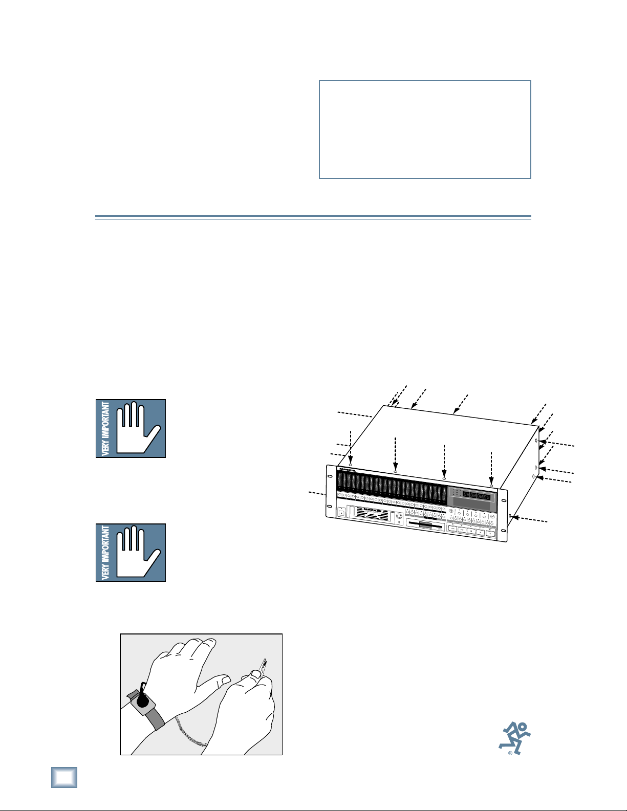
1) Turn off the HDR24/96 and remove the AC
linecord from the socket on the rear panel.
We don’t want this to be a shocking
experience for you!
2) Remove 22 screws from the HDR24/96 cover
using a #2 Phillips screwdriver (4 screws
from the top panel, 4 screws from each side,
and 10 screws from the rear panel). These
screws are all one size.
.
Important: You must have
version 1.3 or higher of the
HDR24/96 OS in order to use the
Serial•9. Follow the installation
instructions with the software
upgrade to install the new
software.
Installing the Serial•9
Important: The Serial•9
contains static-sensitive
components. Anti-static
precautions must be taken before
opening the anti-static bag and
handling the Serial•9. Use an
anti-static wrist strap when performing this installation.
These are available at most computer supply stores.
The use of an anti-static mat is also recommended.
2
4
T
R
A
C
K
/
2
4
B
I
T
O
L
D
I
G
I
O
T
L
A
2
2
4
4
7
7
1
0
1
0
1
5
1
5
2
0
2
0
2
5
2
5
3
0
3
0
3
5
3
5
4
0
4
0
5
0
5
0
21
R
E
C
R
E
C
1
P
O
W
E
R
O
N
L
A
O
L
U
D
I
O
O
L
H
2
2
4
4
7
7
1
0
1
0
1
5
1
5
2
0
2
0
2
5
2
5
3
0
3
0
3
5
3
5
4
0
4
0
5
0
5
0
3
4
R
E
C
R
E
C
32
4
A
R
O
D
L
D
I
S
O
L
K
R
2
2
4
4
7
7
1
0
1
0
1
5
1
5
2
0
2
0
2
5
2
5
3
0
3
0
3
5
3
5
4
0
4
0
5
0
5
0
5
6
R
E
C
R
E
C
R
5
6
E
O
C
L
O
R
D
O
L
E
R
2
2
4
4
7
7
1
0
1
0
1
5
1
5
2
0
2
0
2
5
2
5
3
0
3
0
3
5
3
5
4
0
4
0
5
0
5
0
87
E
C
R
E
C
7
8
/
E
O
D
L
I
T
O
O
R
L
2
O
L
2
O
L
4
2
O
L
4
2
O
L
7
4
2
O
L
7
4
2
1
0
1
5
2
0
2
5
3
0
3
5
4
0
5
0
9
R
E
C
9
O
L
7
4
2
1
0
1
5
2
0
2
5
3
0
3
5
4
0
5
0
0
R
E
C
10
O
L
7
4
2
1
0
1
5
2
0
2
5
3
0
3
5
4
0
5
0
11
R
E
C
11
O
L
7
4
2
1
0
1
5
2
0
2
5
3
0
3
5
4
0
5
0
1
21
R
E
C
O
H
L
7
4
2
1
0
7
4
2
1
0
7
4
1
5
1
0
7
4
1
5
1
0
7
2
0
1
5
1
0
7
2
0
1
5
1
0
2
5
2
0
1
5
1
0
2
5
2
0
1
5
3
0
2
5
2
0
1
5
3
0
2
5
2
0
3
5
3
0
2
5
2
0
3
5
3
0
2
5
4
0
3
5
3
0
2
5
4
0
3
5
3
0
5
0
4
0
3
5
3
0
5
0
4
0
3
5
5
0
4
0
3
5
5
0
4
0
5
0
4
0
5
0
5
0
1
3
1
4
5
1
61
1
7
1
8
1
9
R
E
1312
2
C
R
E
C
R
E
C
R
E
C
R
E
C
1514
R
E
C
16
R
E
C
17
R
18
19
2
L
O
C
1
L
O
C
2
S
T
O
R
L
E
O
O
P
R
1
–
2
S
A
0
E
C
0
E
C
F
E
O
L
2
4
7
1
0
1
5
2
0
2
5
3
0
3
5
4
0
5
0
2
1
R
E
C
21
A
L
L
I
N
P
U
O
L
O
2
2
4
4
7
7
1
0
1
0
1
5
1
5
2
0
2
0
2
5
2
5
3
0
3
0
3
5
3
5
4
0
4
0
5
0
5
0
2
2
R
E
C
22
A
U
T
O
T
I
N
P
U
T
L
O
L
2
4
7
1
0
1
5
2
0
2
5
3
0
3
5
4
0
5
0
2
3
2
4
R
E
C
R
E
C
23
24
A
U
T
O
T
-
C
T
A
O
K
D
E
E
C
H
A
S
E
D
E
L
E
T
D
R
2
4
/
H
I
9
G
H
6
4
4
.
1
/
4
8
4
H
4
.
O
1
k
U
R
S
4
8
k
M
9
6
I
N
k
U
T
E
S
V
A
R
I
1
6
B
I
T
2
4
B
I
T
E
R
R
O
R
T
C
C
L
O
C
K
B
A
R
S
PROJECT: Little love
PLAYLIST: Playlist 1
DRIVE: C:Internal
AVAIL: 01:35:00
S
E
L
E
C
T
S
E
L
E
C
T
S
E
L
E
E
L
A
S
T
T
R
A
C
K
P
R
O
J
E
C
T
B
A
C
K
U
P
D
I
S
K
U
T
I
L
S
Y
S
T
E
M
R
E
W
I
N
D
F
A
S
T
F
W
D
S
T
O
P
R
E
S
O
L
U
T
/
I
9
O
6
N
K
A
S
A
U
M
D
I
P
O
L
E
R
A
T
E
S
S
E
C
O
N
D
S
F
R
A
M
E
S
B
E
A
T
S
T
I
C
K
S
C
T
S
E
L
E
C
T
D
I
G
I
I
/
O
S
Y
N
C
D
E
C
I
N
C
P
L
A
Y
R
E
C
O
R
D
3) Remove the cover by lifting it up at the back
and pulling up and away from the front of the
unit.
Part No. 0000808 Rev. A 07/02
© 2002 Mackie Designs Inc. All rights reserved.
Printed in the U.S.A.
2
Serial•9
Page 3
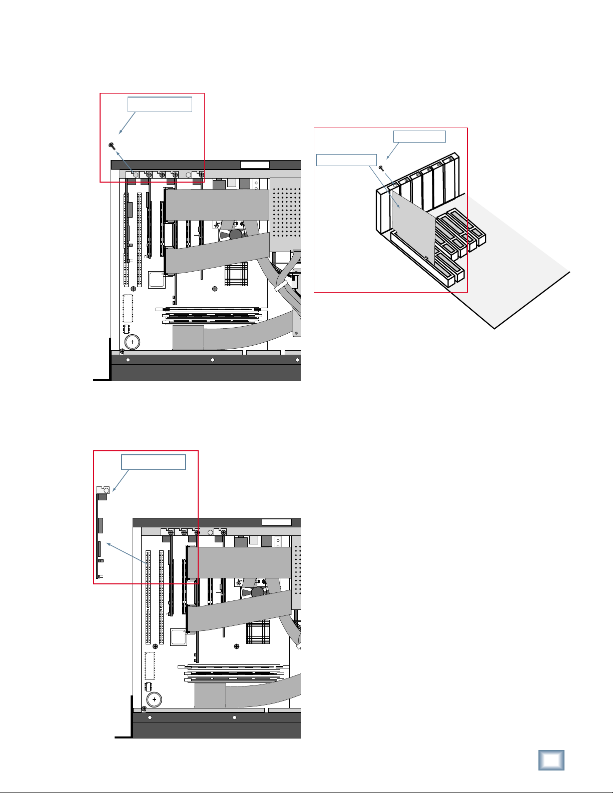
4) Remove the Phillips-head screw securing the
MIDI card. Save the screw for installing the
Serial•9 card.
4) Remove Screw from
MIDI card bracket
REAR PANEL
REAR PANEL
© 2000
MACKIE DESIGNS. ™
®
6) Install the Serial•9 card in the MIDI slot.
Secure it into place with the Phillips-head
screw.
6b) Install Screw into
Serial•9 card bracket
6a) Gently press the Serial•9
card into the slot
Installation Guide
FRONT PANEL
5) Remove the MIDI card by gently lifting up on
the card and bracket to remove it from the
socket on the board.
5) Remove MIDI card
REAR PANEL
REAR PANEL
© 2000
MACKIE DESIGNS. ™
®
7) Replace the cover, reinstall the screws, and
you’re ready to go!
FRONT PANEL
Installation Guide
3
Page 4
Making the Connections
Specifications
MIDI Connection
The MIDI connection on the Serial•9 card is the
same as the MIDI connection on the MIDI card it is
replacing. Simply connect the supplied MIDI
breakout cable to the bottom 9-pin connector on the
Serial•9 card, and connect the 5-pin MIDI IN and
MIDI OUT connectors to your MIDI interface.
Serial 9-Pin Connection
The Serial 9-Pin connection on the Serial•9 card
is an RS-422 port that supports the Sony
device protocol. Connect the upper 9-pin connector
to any industry standard Sony 9-Pin controller or
device using a DB9 male to DB9 male serial computer
cable (available at most computer supply outlets).
Note: Make sure your Sony 9-Pin controller or
device accepts a male DB9 connector.
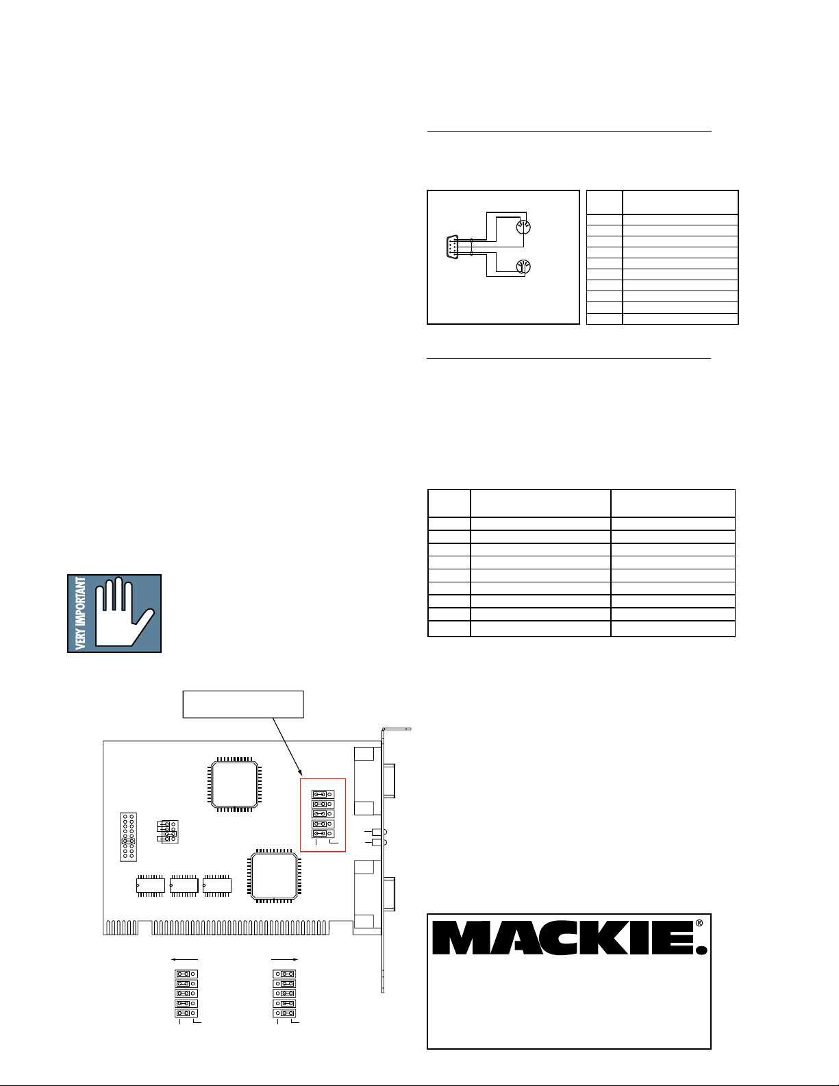
The Serial•9 card is shipped configured to
operate as a device (DEV); that is, to connect to a
controller and be controlled. This is indicated by the
green LED on the Serial•9 card.
It is possible to configure the Serial•9 to be the
controller (CONT), to control another device. Simply
move the five jumpers (JP1–JP5) on the Serial•9
card as shown in the illustration below to configure
the card as a controller. This is indicated by the red
LED on the Serial •9 card.
Note: HDR24/96 software version 1.3
supports only device (DEV) protocol for the
Serial•9. Please refer to the Software
Release Notes, which can be found on Mackie
website’s HDR24/96 software downloads
page, for complete information on the support
of Serial•9 for all software versions.
®
9-Pin
MIDI
Electrical Interface: MIDI 1.0 Specification
Data Rate: 31.25 kb/sec
Pinout:
MIDI
2
54
13
2
54
MIDI
OUT
13
MIDI
1
6
9
5
IN
MIDI Breakout Cable
9-Pin Function
1 MIDI OUT Pin 4
2
3
4
5 MIDI IN Pin 4
6 MIDI OUT Pin 5
7
8
9 MIDI IN Pin 5
Shell MIDI OUT Pin 2
Serial 9-Pin
Electrical Interface: EIA RS-422-A
Data Rate: 38.4 kb/sec
Parity: Odd
Data Bits: 8
Stop Bits: 1
Indicators: Green LED (Device)
Red LED (Controller)
Pinout:
Serial Device Controller
9-Pin Function Function
1 Frame Ground Frame Ground
2 Transmit A (–) Receive A (–)
3 Receive B (+) Transmit B (+)
4 Receive Common Transmit Common
5 N/C N/C
6 Transmit Common Receive Common
7 Transmit B (+) Receive B (+)
8 Receive A (–) Transmit A (–)
9 Frame Ground Frame Ground
DEVICE/CONTROLLER
CONFIGURATION JUMPERS
JP2
IRQ
I/O BASE
IRQ2/9
ADDRESS
IRQ3
BASE4
IRQ4
BASE5
IRQ5
BASE6
IRQ7
BASE8
IRQ10
IRQ11
IRQ12
IRQ15
DEVICE
CONFIGURATION
JP2
DEVICE
JP3
JP4
JP5
JP1
CONTROLLER
CONTROLLER
CONFIGURATION
DEVICE
JP2
JP3
JP4
JP5
JP1
CONTROLLER
DEVICE
Serial•9 Device/Controller Configuration
J2
JP3
JP4
JP5
JP1
CONTROLLER
J1
DEVICE
SERIAL•9MIDI
“Mackie,” the “Running Man” figure, and “Serial•9”
are trademarks or registered trademarks of Mackie
Designs Inc. All other brand names mentioned are
trademarks or registered trademarks of their
respective holders, and are hereby acknowledged.
© 2002 Mackie Designs Inc.
All Rights Reserved.
Printed in the U.S.A.
16220 Wood-Red Rd. NE • Woodinville, WA 98072 • USA
Europe, Asia, Central & South America: 425/487-4333
US & Canada: 800/898-3211
Middle East & Africa: 31-20-654-4000
Fax: 425/487-4337 • www.mackie.com
E-mail: sales@mackie.com
 Loading...