

Page 1
SDR24/96 Quick-Start Guide
24 TRACK/24 BIT DIGITAL AUDIO RECORDER
POWER
DELETE
LAST
TRACK PROJECT
HIGH RESOLUTION
X2
24 BIT16 BIT
FAST FWD
96
NON-LINEAR RECORDER
MINUTESHOURS SECONDS FRAMES
PLAY
STOP
EXT
CLOCK
SELECTSELECTSELECTSELECT
RECORD
SDR
44.1k
48k
ERROR
VARI
TC
PROJECT: Feel the Love
AVAIL: 02:27:26 on EXT
21
2019181716151413121110987654321
EDIT
SETUP
PUNCH REHRSELOOPLOCATE STORE
242322
T-CODE
AUTO
CHASE
TAKE
ALL
AUTO
INPUT
INPUT
REWIND
Getting Started
Project
• Start a new project (PROJECT:New). Either accept
the default name (Project#1) by selecting New, or press
Page Right
press Page Left
I/O
• Choose either the analog inputs or digital inputs using
the INPUT TYPE SELECT menu (SETUP:I/O:Page
Right Twice
a combination of both.
See “Hookups” on page 12 of the Operation Manual for
examples of both analog and digital connections.
• By default, track numbers are assigned to their
corresponding inputs and outputs. You can customize
the mapping of the inputs (SETUP:I/O:TRACK INPUT
SELECT) and outputs (SETUP:I/O:Page Right
TRACK OUTPUT SELECT) to different tracks.
Sync:
• Choose the sample clock source (SETUP:Sync:SClk).
If the SDR24/96 is providing the master clock, select
Internal. If the SDR is a slave and syncing to an
external clock through the Word Clock input, select
Word Clock. Select ADAT A, B, or C if syncing to a selfclocking ADAT™ optical input.
• Choose the sample rate (SETUP:Sync:SRate). When
recording with the analog inputs, choose any sample
rate appropriate for your project. You must use the same
sample rate throughout a project. When recording with
the digital inputs, the sample rate must be the same as
the digital source.
• Choose your preferred sample size (SETUP:Sync:Page
Right
• Choose the time code source (SETUP:Sync:TcSrc) if
the SDR is chasing to time code (T-CODE CHASE). Use
Jam Continuous when all devices are synced to the
same master clock. Use Chase when the you are using
the SDR24/96’s internal sample clock (no external clock
connected) and you want to sync to external time code.
to enter a new name. When finished,
and select New.
:INPUT TYPE SELECT), or customize
:
:SSize), either 16-bit or 24-bit.
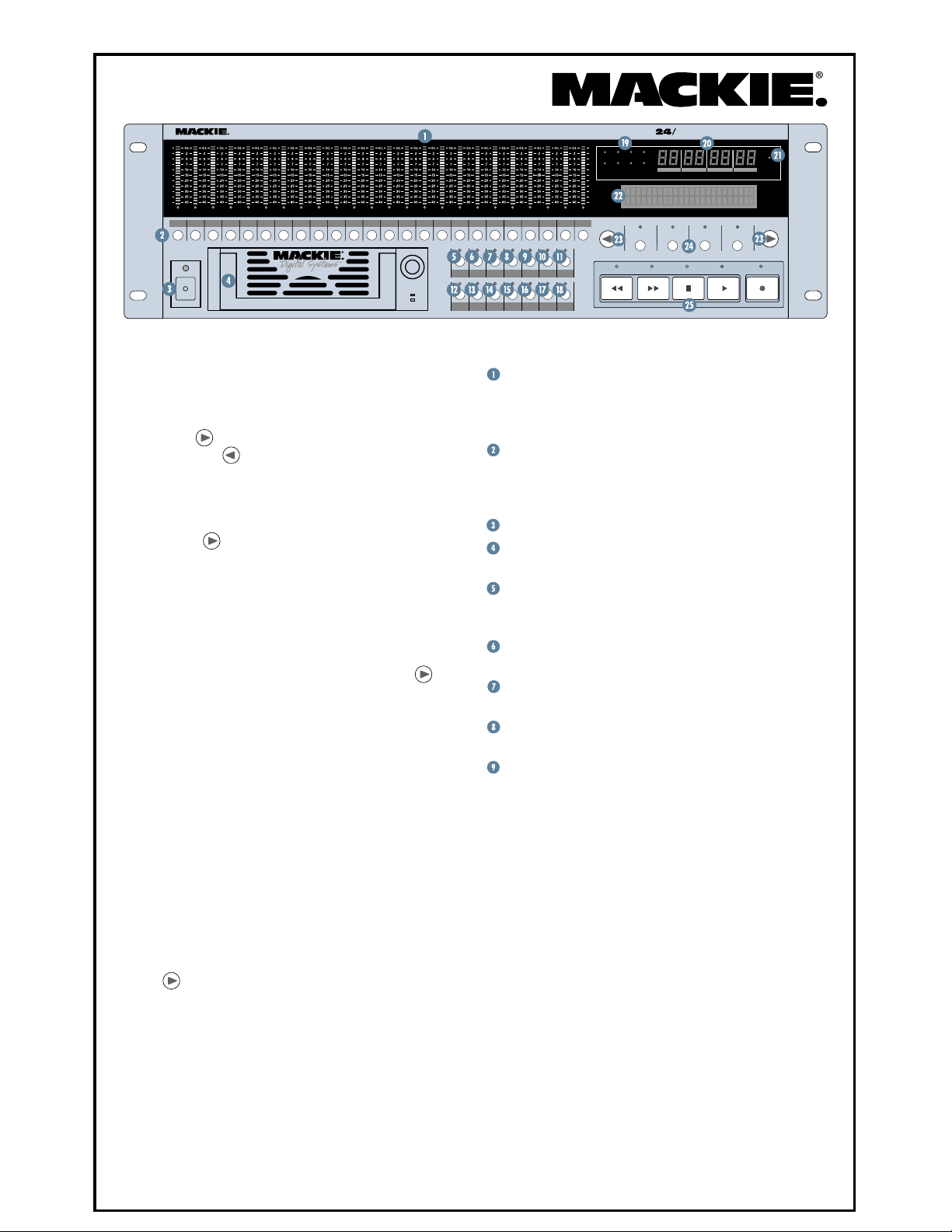
Front Panel Description
Channel Level Indicators: Indicate the signal level
at the inputs or outputs, depending on the monitoring
mode selected. OL on the meter corresponds to +22 dBu
at the analog input, and 0 dBFS at the digital input.
Record Ready Buttons: Used to arm tracks for
recording, or to select tracks for editing. The red LED at
the bottom of the meter blinks while in Record Standby,
and lights steadily while actually recording.
POWER Switch: Turns the SDR24/96 on and off.
Drive Bay: For removable drives like the Mackie
Media M•90 and the Project ORB™ cartridge.
DELETE LAST: Deletes the last record pass (must
be the last action in the History List). You cannot undo
Delete Last.
TRACK: Accesses track options including Mute,
Virtual Tracks, and Track Name.
PROJECT: Accesses project options including New,
Open, Save, Save As, Delete, Copy, Rename, and Purge.
EDIT: Accesses common editing functions such as
Delete, Cut, Copy, Paste, Place, Undo, and Redo.
SETUP: Accesses the following options:
• Record Options
♦
Record Safe
♦
Preroll before Locator♦ Auto Take Mode
♦
Preroll
♦
Postroll
• I/O Options
♦
Track Input Select
♦
Track Output Select
• Sync Options
♦
Sample Clock
♦
Sample Rate
♦
Time Code Source
♦
Frame Rate
• Transport Options
♦
Locate 1-4
♦
Current Locator Position♦ Relative Mode
♦
Transport Offset
• Disk Options
♦
Mount Drive
♦
Format Drive
• System Options
♦
USB Mass Storage Mode♦ System Load
♦
SDR Footswitch
♦
Remote Footswitch
♦
Locator Mode
♦
One Button Record
♦
Input Type Select
♦
Sample Size
♦
LTC Out
♦
MTC Out
♦
VariSpeed
♦
Relative Offset
♦
Auto Play
♦
Defragment Drive
♦
Date
♦
Time
♦
About
Page 2
POWER
24 TRACK/24 BIT DIGITAL AUDIO RECORDER
ANALOG OUT 1 - 8 ANALOG OUT 9 - 16 ANALOG OUT 17 - 24
ANALOG IN 1 - 8 ANALOG IN 9 - 16 ANALOG IN 17 - 24
SDR
44.1k
48k
ERROR
VARI
TC
PROJECT: Feel the Love
AVAIL: 02:27:26 on EXT
21
2019181716151413121110987654321
DELETE
EDIT
SETUP
TRACK PROJECT
LAST
PUNCH REHRSELOOPLOCATE STORE
242322
T-CODE
AUTO
TAKE
ALL
INPUT
REWIND
CHASE
AUTO
INPUT
X2
24 BIT16 BIT
FAST FWD
NON-LINEAR RECORDER
MINUTESHOURS SECONDS FRAMES
STOP
SDR
24 TRACK/24 BIT DIGITAL
AUDIO RECORDER
96
SELECTSELECTSELECTSELECT
PLAY
HIGH RESOLUTION
NON-LINEAR RECORDER
RECORD
EXT
CLOCK
HIGH RESOLUTION
96
POWER
100 - 240V 250mA
50/60Hz
REGISTERED TRADEMARKS OF MACKIE DESIGNS INC.: "MACKIE.", MACKIE DIGITAL SYSTEMS AND THE "RUNNING MAN" FIGURE.
DIGITAL WORD CLOCK I/O MIDI
DIGITAL
9 - 16
IN OUT
X2
5-8X29-12
DIGITAL
17 - 24
IN OUT
1 - 8
USB
IN OUT
X2
1-4
CONCEIVED, DESIGNED, AND MANUFACTURED BY MACKIE DESIGNS INC • WOODINVILLE • WA 98072 • USA
MADE IN USA • FABRIQUE AU USA • PATENTS PENDING COPYRIGHT ©1998 THE FOLLOWING ARE TRADEMARKS OR
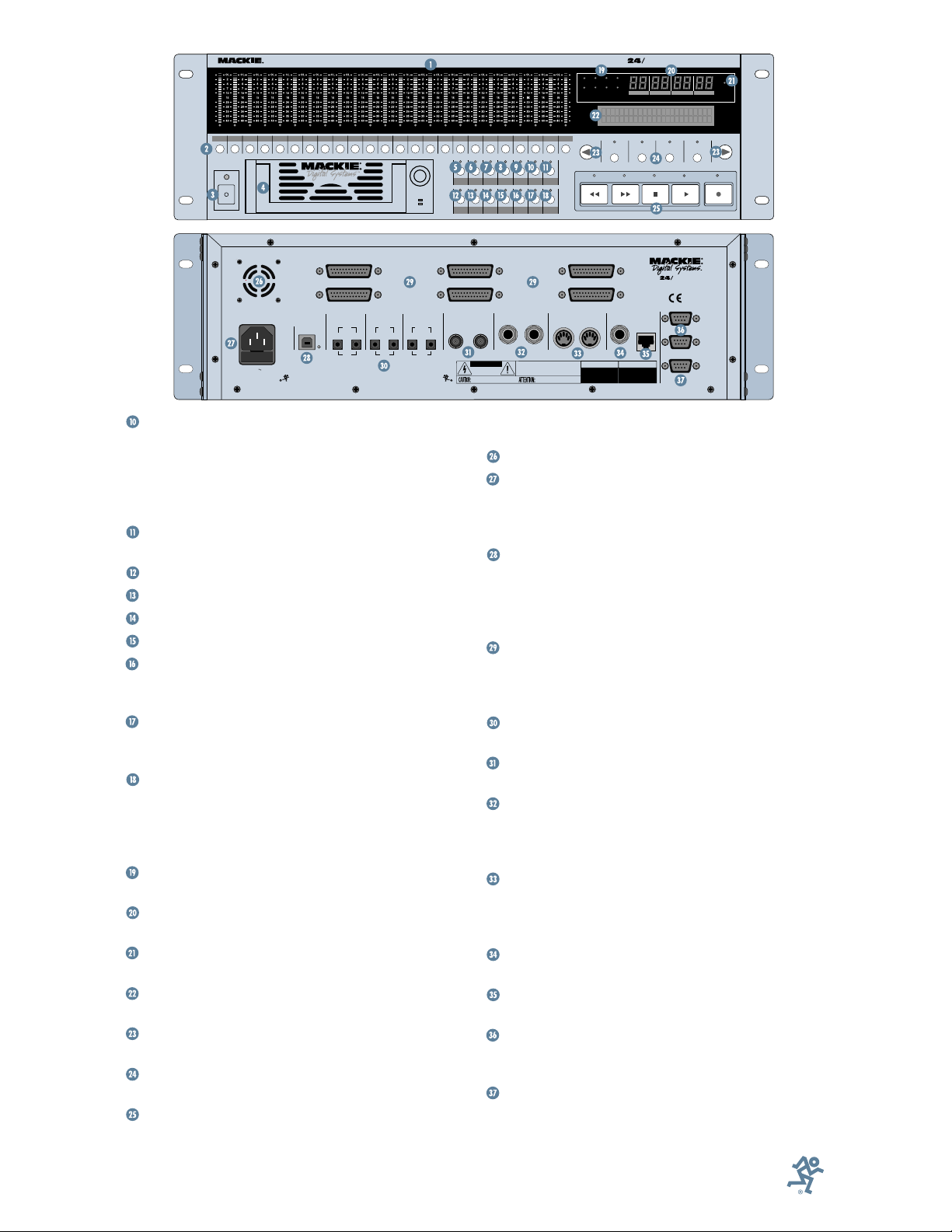
AUTO TAKE: Used for multiple record passes. When
Auto Increment mode is selected, virtual track numbers
are automatically incremented after each record pass.
In Auto Edit mode, multiple recordings take place on
the same virtual track, but previously recorded audio for
the take is shifted down to the next virtual track.
T-CODE CHASE: Allows the SDR24/96 to sync to
external time code.
LOCATE: Jump to Locate 1, 2, 3, or 4.
STORE: Store Locate points 1-4.
LOOP: Enables looped playback or recording.
PUNCH: Enables Auto Punch mode.
REHEARSE: Use to practice punching-in and
punching-out. Punch-in and punch-out points are
automatically saved to Locates 3 and 4, respectively.
ALL INPUT: Both armed and unarmed tracks
monitor their inputs in Play and Record. Use for
rehearsing and level-setting.
AUTO INPUT: Both armed and unarmed tracks
monitor their previously recorded audio in Play, and
armed tracks monitor their inputs in Record (unarmed
tracks still monitor their previously recorded audio).
Use for recording.
Status Display: Error, Sample Rate, Word Length,
VariSpeed, and Time Code Sync indicators.
Current Time Display: Shows the current locator
time in Hours:Minutes:Seconds:Frames.
EXT CLOCK: Indicates when the SDR24/96 syncs to
an external clock.
LCD Display: Backlit 2x24-segment display provides
selection options for the four SELECT buttons.
Page Left and Page Right Buttons: Used to scroll
through the menus in the display.
SELECT Buttons: Used to select options in the
display.
Transport Controls: Includes Rewind, Fast Forward,
Stop, Play and Record.
Part No. 820-260-00 Rev. A1 03/02
© 2002 Mackie Designs Inc. All rights reserved.
Printed in the U.S.A.
OUT
CAUTION
RISK OF ELECTRIC SHOCK
DO NOT OPEN
REPLACE WITH THE SAME TYPE FUSE AND RATING.
DISCONNECT SUPPLY CORD BEFORE CHANGING FUSE
SMPTE
OUT
IN
WARNING:
TO REDUCE THE RISK OF FIRE OR ELECTRIC SHOCK, DO NOT
EXPOSE THIS EQUIPMENT TO RAIN OR MOISTURE. DO NOT REMOVE COVER.
NO USER SERVICEABLE PARTS INSIDE. REFER SERVICING TO QUALIFIED PERSONNEL.
AVIS:
RISQUE DE CHOC ELECTRIQUE — NE PAS OUVRIR
UTILISE UN FUSIBLE DE RECHANGE DE MÊME TYPE.
DEBRANCHER AVANT DE REMPLACER LE FUSIBLE
ININOUT
SERIAL NUMBER
FOOT
SWITCH
MANUFACTURING DATE
MICRO/
REMOTE 24
CNTRL
ADAT SYNC
OUT
ADAT SYNC
IN
SERIAL
9-PIN
Rear Panel Features
Fan: Keeps the SDR24/96 running cool.
IEC Socket: Connect the detachable linecord here.
The SDR24/96 has a universal switching power supply
and accepts an AC line voltage between 100 and 240
VAC. No voltage select switch to worry about!
USB: Use to connect to a USB (Universal Serial Bus)
port on a PC or Macintosh computer to backup and
transfer files. The SDR24/96 must be in USB Mass
Storage Mode (SETUP:Page Right:System:USBMS) to
use the USB port.
ANALOG INputs and OUTputs: DB25 Female
connectors send and receive balanced analog line-level
signals. See “Appendix D” in the Operation Manual for the
pinout diagram, and “Appendix E” for compatible cables.
DIGITAL INputs and OUTputs: ADAT™ optical
format send and receive digital audio signals.
WORD CLOCK IN and OUT: BNC connectors send
and receive word clock signals.
SMPTE IN and OUT: 1/4" TRS connectors send and
receive SMPTE LTC (Longitudinal Time Code). LTC
Output can be manually turned on and off
(SETUP:Sync:Page Right:LtcO).
MIDI IN and OUT: 5-Pin DIN connectors send and
receive MTC (MIDI Time Code) and MMC (MIDI
Machine Control). MTC Output can be manually turned
on and off (SETUP:Sync:Page Right:MtcO).
FOOTSWITCH: 1/4" TS jack for footswitch control
of Play/Stop or Punch In/Punch Out.
REMOTE: RJ-45 connector for the optional Micro
Remote or Remote 24.
ADAT SYNC IN and OUT: DB9 Female connectors
for connecting to the Sync connections on an ADAT
multitrack recorder.
SERIAL 9-PIN: DB9 Female connector for
connecting transport controllers that use the EIA
RS-422 serial data communication standard (supports
®
9-Pin protocol).
Sony
 Loading...