

Page 1
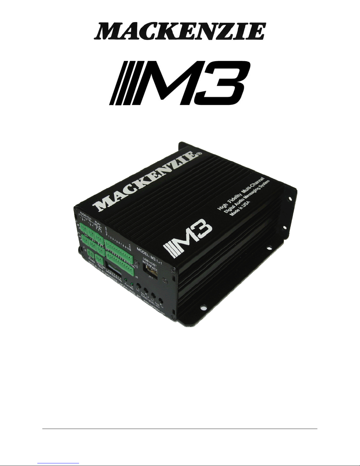
HIGH FIDELITY MULTI-CHANNEL
DIGITAL AUDIO PLAYER
MACKENZIE LABORATORIES, INC.
1163 Nicole Court
Glendora, CA 91740 USA
User's Manual
Version 1.0 Revised 13, Sept 2011
Doc 99-20-088 - $25.00
Tel: (909) 394-9007 Fax: (909) 394-9411
Web: www.macklabs.com
Email: [email protected]
Page 2

General Safety Instructions
Always follow these basic safety precautions when using the system:
1. Read carefully and understand all instructions.
2. Follow all warnings and instructions marked on the product.
3. DO NOT block or cover ventilation slots and openings.
4. DO NOT place the product in a closed enclosure or cabinet unless proper ventilation is provided.
5. Never spill liquid on the product or drop objects into the ventilation slots and openings. Doing so my result in
serious damage to the components.
6. Repair or service must be performed by a factory authorized repair facility.
7. DO NOT staple or otherwise attach the power supply cord to building surface.
8. DO NOT use the product near or in wet or damp places, such as wet basements.
9. DO NOT use extension cord. Install within 6 feet of a grounded outlet receptacle.
10. DO NOT install during lightning storm.
11. Never touch un-insulated wires or terminals unless the unit is disconnected from both power and the rest of
the phone system.
12. Use Caution when installing or modifying configuration switches or control lines.
13. The unit must be securely attached to a wall board, rack or table mounted.
Regulations:
FCC (Part 15) Radio Frequency Interference
The M3 generates and uses radio frequency energy and if not installed and used in strict a cco rdance with the
manufacturer's instructions, may cause interference to radio and television reception. Unit complies with the
limits for Class A devices in accordance with the specifications in Subpart J of Part 15 of the FCC Rules. This
testing is designed to provide reasonable protection against such interference. However, there is no guarantee
that interference will not occur in a particular installation. If this equipment does cause interference to radio or
television reception, which can be determined by turning the unit off and on, the user is encouraged to try to
correct the interference by one or more of the following measures:
-Reorient the radio or TV receiving antenna.
-Relocate the unit with respect to the radio or TV receiver or vice-versa.
-Plug the unit into a different outlet so that it and the radio or TV receiver are on different branch circuits
-If necessary, the user should consult the dealer or an experienced radio/television technician for additional
suggestions.
M3 User's Manual V 1.0 Revised 13, Sept 2011 Page 2
Page 3

Table of Contents
1. OVERVIEW .......................................................................................................................................................................... 4
1.1. Features and Capabilities ................................................................................................................................................... 4
1.2. General Specifications ....................................................................................................................................................... 5
1.3. Hardware Configurations................................................................................................................................................... 6
1.3.1. M3.1 .......................................................................................................................................................................... 6
1.3.2. M3.1+1 ...................................................................................................................................................................... 6
1.3.3. M3.2 .......................................................................................................................................................................... 6
2. Installation & Configuration .................................................................................................................................................. 7
2.1. Installation Steps ............................................................................................................................................................... 7
2.2. Configuration and Features (M3.1, M3.1+1, M3.2) .......................................................................................................... 7
2.2.1. Power ........................................................................................................................................................................ 7
2.2.2. Audio Out .................................................................................................................................................................. 7
2.2.3. Audio Level Adjust ................................................................................................................................................... 8
2.2.4. Relay ......................................................................................................................................................................... 8
2.2.5. Remote Control ......................................................................................................................................................... 8
2.2.6. Playing LED .............................................................................................................................................................. 8
2.2.7. Config Switches ........................................................................................................................................................ 9
2.2.8. Play Mode: .............................................................................................................................................................. 10
2.2.9. RS-232 Hardware Configuration: ............................................................................................................................ 11
2.2.10. USB connector .................................................................................................................................................... 11
2.3. M3.1 Enhanced Configuration and Features: .................................................................................................................. 11
2.4. M3.1+1 Enhanced Configuration and Features: .............................................................................................................. 11
2.4.1. CH 2, Audio Out: .................................................................................................................................................... 11
2.4.2. CH 2, Audio Level Adjust: ...................................................................................................................................... 12
2.4.3. CH 2, Relay: ............................................................................................................................................................ 12
2.4.4. CH 2, Remote Control: ............................................................................................................................................ 12
2.4.5. CH 2, Playing LED ................................................................................................................................................. 12
2.5. M3.2 Enhanced Configuration and Features: .................................................................................................................. 13
2.5.1. Remote Control, 11 - 20: ......................................................................................................................................... 13
3. AUDIO FILE FORMATTING ............................................................................................................................................ 13
4. RS-232 Commands: ............................................................................................................................................................. 14
4.1. System functional commands .......................................................................................................................................... 14
4.2. System configuration commands ..................................................................................................................................... 14
4.3. System description commands ........................................................................................................................................ 14
4.4. Enhanced System commands .......................................................................................................................................... 14
4.5. RS232 Command Syntax ................................................................................................................................................. 15
4.5.1. Play snippet command ............................................................................................................................................ 15
4.5.2. Stop command ......................................................................................................................................................... 15
4.5.3. System reset command ............................................................................................................................................ 16
4.5.4. Initiate Upload File (Read from M3) ....................................................................................................................... 16
4.5.5. Initiate download file (Write to the M3) ................................................................................................................ 16
4.5.6. Delete file ................................................................................................................................................................ 16
4.5.7. RS232 Serial Port Speed ......................................................................................................................................... 17
4.5.8. Restore Default Configuration ................................................................................................................................ 17
4.5.9. Format SD Card ...................................................................................................................................................... 17
4.5.10. Format SD Card and Restore Factory Defaults ................................................................................................... 18
4.5.11. Set Delay Before Play ......................................................................................................................................... 18
4.5.12. Set Pause Between Plays ..................................................................................................................................... 18
4.5.13. Set Number of Plays ........................................................................................................................................... 19
4.5.14. Set Message Priority ........................................................................................................................................... 19
4.5.15. Display system information ................................................................................................................................ 20
4.5.16. Command Listing ................................................................................................................................................ 20
4.5.17. Display Message Listing ..................................................................................................................................... 21
4.5.18. Set Time of Day .................................................................................................................................................. 21
4.5.19. Set Date ............................................................................................................................................................... 21
4.5.20. Set Bass Amount ................................................................................................................................................. 22
4.5.21. Set Treble Amount .............................................................................................................................................. 22
4.5.22. Update Firmware ................................................................................................................................................. 22
5. Memory Card Removal/Installation: ................................................................................................................................... 23
5.1. Removal ........................................................................................................................................................................... 23
5.2. Installation ....................................................................................................................................................................... 23
5.3. Capacity, Data Rates and Part Numbers: ......................................................................................................................... 23
M3 User's Manual V 1.0 Revised 13, Sept 2011 Page 3
Page 4

Shipping Container Contents
The following items should be found in the container of Digital Audio Record/Play System
• M3 System
• Installation and User Guide
• Set of four rubber feet
Optional Accessories:
• M3-PS - 12VDC 1.0 amp power pack
• M3-SW, Composer software
• SD Card memory
• M3-RM-x - M3 rack mount packaging. 1U package contains power supply and houses up to 4 M3
modules. Must be ordered as a system, not field upgradable.
1. OVERVIEW
1.1. Features and Capabilities
The Mackenzie M3 system is the most flexible series of high fidelity, multi-channel solid state digital
audio playback systems available to the industry. The M3 is backed by Mackenzie’s years of system
design experience.
The M3 retrieves MPEG (MP3) audio data from non-volatile SD Card memory, eliminating the need for
battery backup, and delivers superb full bandwidth sound quality.
The M3 is offered in the following configurations:
Model # Description
M3.1 Single Balanced Stereo audio channel, 10 message
input selections, RS232, wall mount package
M3.1+1 Dual Balanced Stereo audio channels, 10 message
input selections each, RS232, wall mount package
M3.2 Single Balanced Stereo audio channel, 20 message
input selections, RS232, wall mount package
M3-RM-x M3 rack mount packaging. 1U package contains power
supply and houses up to 4 M3 modules. Must be
ordered as a system, not field upgradable.
Messages are stored on SD Card memory cards (1GB included). Messages are randomly and instantly
accessible. Messages are stored as FAT formatted M3 allowing each of the messages to be of
different duration. DML also provides for replacement messages to be a different length than the
original, maximizing memory efficiency and compatibility with future applications.
Messages are stored in MPEG I, Layer III format. Composer software allows a Windows computer to
create entire programs with .WAV files then converts them to MPEG. The MPEG files then may be
copied to the a PCMCIA drive on the computer or downloaded directly to the M3 over the RS232 port
Message playback is controlled by simple contact closures or by RS232 commands. Audio outputs are
balanced and level is controlled via potentiometers. Form C relay connections are provided to indicate
that the M3 is playing on each audio channel.
The M3 offers several different playback modes to accommodate different applications. Play/repeat,
Play once per closure, Play while active, and Retrigger allow the user to customize input logic. Message
repetition and delay between messages are user selectable as well.
The M3's small size, industrial construction and the absence of moving parts makes it ideal for
automatic unattended operation, especially in harsh environmental or mobile conditions.
M3 User's Manual V 1.0 Revised 13, Sept 2011 Page 4
Page 5

1.2. General Specifications
Audio Quality
Sample Rate: 44.1kHz
Dynamic Range: 85dB
Frequency Resp.: 20Hz - 20kHz
THD: <0.1% at 1kHz
Audio Output
Type: Balanced, analog
Mode: Stereo or dual mono*
Connection: Pluggable euro terminals
Level: +4dB max., 150 ohm
Adjust: Potentiometer
Audio Memory
Type: FAT formatted SD Card
Power
Input Voltage: 12VDC @ 1 amp
Connection: 2 pin, 3.81mm euro terminal
Audio Data Formats
Compressed: MPEG 1, Layer III
Rates(mono): 7kHz = 32k bits per sec.
15kHz = 64k bits per sec.
20kHz = 128k bits per sec.
Control I/O
Control Inputs: Individual message start, stop
RS232: 115.2kbaud (9.6k optional),
8 data bits,1 stop bit, no parity
Relay Outputs: Playing
Interface: 2.5mm spring terminals
Mechanical
Wall Mount/Table top 5.7"W x 6" L x 2.4" H
Rack mount 1U
Chassis Aluminum extrusion, painted
M3 User's Manual V 1.0 Revised 13, Sept 2011 Page 5
Page 6

1.3. Hardware Configurations
1.3.1. M3.1
Single Balanced Stereo audio channel, 10 message input selections, RS232, wall mount/table top
package.
Left channel balanced audio output
Right channel balanced audio output
Relay(Form C)
Stop contact
Start contacts 1 - 10
Input Common
Power Connection
CH2 Audio Level Adjustments, L/R
Channel 1 Playing LED
Configuration Switches
RS232 Connection
1.3.2. M3.1+1
Dual Balanced Stereo audio channels, 10 message input selections each, RS232, wall mount/table
top package.
Interfaces of M3.1 PLUS,
Channel 2(CH2):
Left channel balanced audio output
Right channel balanced audio output
Relay(Form C)
Stop contact
Start contacts 1 - 10
Input Common
CH2 Audio Level Adjustments, L/R
Channel 2 Playing LED
1.3.3. M3.2
Single Balanced Stereo audio channel, 20 message input selections, RS232, wall/table top mount
package.
Interfaces of M3.1 PLUS,
Second Stop contact
Start contacts 11 - 20
Second Input Common
M3 User's Manual V 1.0 Revised 13, Sept 2011 Page 6
Page 7

2. Installation & Configuration
This section provides complete instructions for mounting the M3 High Fidelity Multi-Channel Digital Audio
Player on a Wall or Table. It also illustrates all interface requirements to auxiliary equipment, including
inputs and outputs. Configuration switch settings are provided.
2.1. Installation Steps
These are the general steps for installation.
1. Find a space on the wall or table. For table top applications, install included rubber feet. Allow
approximately 6 inches in front of, and 6 inches in back of the unit for user access to memory and
wiring.
2. Mount the unit to the selected place with its wiring at least 18” away from power supply or other
equipment that generates electrical noise.
3. If you are using the optional power supply, make sure there is a standard electrical outlet available.
4. Connect audio outputs.
5. Connect control inputs and outputs.
6. Set DIP switches to the desired operation.
7. Verify memory is installed. If the unit was programmed in the factory, the memory will already be
installed in the unit. If you plan to create your own messages, the memory will be shipped
separately. Refer to Section 5 for additional information on checking memory.
8. Connect and apply power.
9. Test unit operation.
2.2. Configuration and Features (M3.1, M3.1+1, M3.2)
This section documents the features and functions common to all versions of the M3.
2.2.1. Power
2 terminal pluggable connector.
+ 12 VDC at 1 amp
- Ground
The plug is a rising clamp style termination that accepts up to 16 gauge wire. To insert wire loosen
the screw on the top of the plug, insert the wire into the side of the plug, then tighten the screw.
2.2.2. Audio Out
Two, 3 terminal pluggable connectors.
L - Left audio output, inverting
L
L + Left audio output, non-inverting
R - Right audio output, inverting
R
R + Right audio output, non-inverting
M3 supports balanced audio output. If unbalanced (single ended) is desired, use audio output noninverting and audio output ground.
The plug is a spring clamp style termination that accepts up to 16 gauge wire. To inse rt wire, insert
a jewelers screwdriver into the upper section of the connection until the spring clamp opens in the
lower section. Insert the uninsulated wire, and remove the screwdriver ca using the clamp to grab
the wire.
Left audio output ground
Right audio output ground
M3 User's Manual V 1.0 Revised 13, Sept 2011 Page 7
Page 8
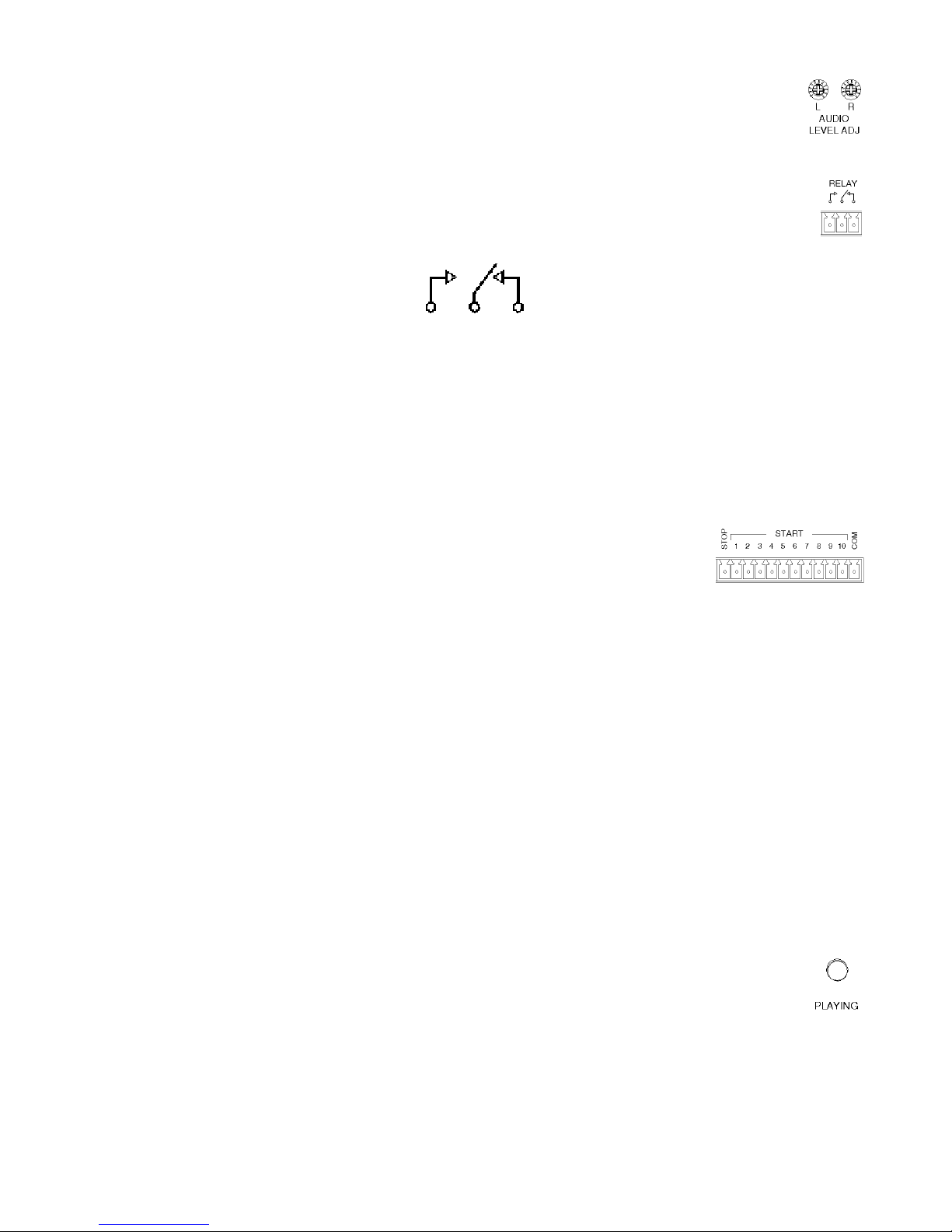
2.2.3. Audio Level Adjust
Two potentiometers adjust playback level of the left and right channels individually. Range
is continuous from -infinity to +3dBm.
2.2.4. Relay
Playing relay is a Form C contact closure. This contact is activated for the length of the
playing message and is released when the message ends or is stopped. The playing relay
is capable of handling 1A at 24VDC or 0.25A at 110VAC, non-inductive load.
Normally
Open
Common
Normally
Closed
The plug is a spring clamp style termination that accepts up to 16 gauge wire. To inse rt wire, insert
a jewelers screwdriver into the upper section of the connection until the spring clamp opens in the
lower section. Insert the uninsulated wire, and remove the screwdriver ca using the clamp to grab
the wire.
2.2.5. Remote Control
12 position pluggable terminal strip. Use for remote control start of message
playback and stopping messages.
Stop Connect to common to stop message playback
Start 1 Connect to common for message 1 playback
Start 2 Connect to common for message 2 playback
Start 3 Connect to common for message 3 playback
Start 4 Connect to common for message 4 playback
Start 5 Connect to common for message 5 playback
Start 6 Connect to common for message 6 playback
Start 7 Connect to common for message 7 playback
Start 8 Connect to common for message 8 playback
Start 9 Connect to common for message 9 playback
Start 10 Connect to common for message 10 playback
Com Connecting any input to common activates the function
The plug is a spring clamp style termination that accepts up to 16 gauge wire. To inse rt wire, insert
a jewelers screwdriver into the upper section of the connection until the spring clamp opens in the
lower section. Insert the uninsulated wire, and remove the screwdriver ca using the clamp to grab
the wire.
2.2.6. Playing LED
Green LED which indicates the playing and boot status of the M3.
Off M3 is not playing or no power supplied to the unit
On M3 is playing
Blink M3 is executing other functions
M3 User's Manual V 1.0 Revised 13, Sept 2011 Page 8
Page 9
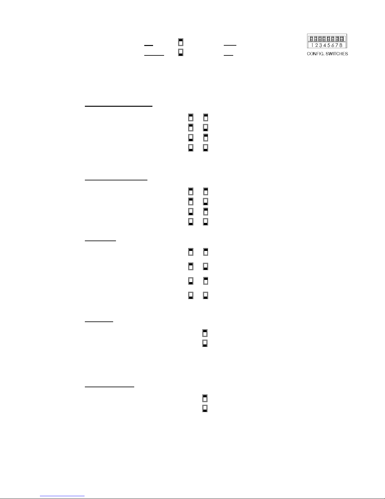
2.2.7. Configuration Switches
8 position DIP Switch:
DOWN
This user adjustable dip switch is provided to allow the user to tailor the operation of the M3 to meet
their demands. Note: This dip switch is read by the CPU only upon power up. Changing the
position of the dip switch while the module is powered up will have no affect on the
operation of the system.
Number of Plays - 1 , 2
For applications where messages
need to be repeated due to noise
or for clarity. Repeating
messages in this fashion eases
system overhead. Global setting
for all messages. When message
is activated, it will play the
programmed number of times.
UP
Position is OFF
Position is ON
1 2
Play activated message one time
Play activated message two times
Play activated message three times
Play activated message four times
Delay Between Plays
Messages played immediately
after one another can be
confusing to the listener. Allowing
a delay time can make the
playback easier to understand.
Global setting for all messages.
3 4
One second delay between plays
Five second delay between plays
Ten second delay between plays
Thirty second delay between plays
Play Mode
Defines playback mode of
message sequences. Message
sequences are comprised of
message material, number of
plays and delay between plays
5 6
Standard operation - described in
Section 2.2.8
Play one sequence per closure described in Section 2.2.8
Play while active - described in
Section 2.2.8
Re-trigger - described in Section
2.2.8
Play Next
Enabling next message allows Start
10(Remote Control connector, Start
10) to initiate playback of next valid
message sequence. First input after
power on will play message 1. All
operation modes are supported and
other start inputs are disabled.
Memory Protect
Allows user to lock message memory
so that messages may not be
accidentally overwritten.
7
Disable
Enable
8
Unlock message memory
Lock message memory
M3 User's Manual V 1.0 Revised 13, Sept 2011 Page 9
Page 10

2.2.8. Play Mode:
Standard Operation: A momentary contact closure causes the device to play one sequence of the
message corresponding to that input. A sequence being the number of plays selected by the dip
switches and the selected delay time which separates them. If a contact is maintained active, the
system will continuously play that message repeatedly until the input is released at which time the
system will finish the current playback sequence and then stop.
If multiple inputs are held active the system will play one sequence of the first message and then
cycle through any other active messages sequentially based on the order which they were input.
The message corresponding to the lower input number will have priority should multiple inputs be
activated at exactly the same time.
If a momentary contact closure is provided while a message is playing and it is released prior to the
ending of the message play, it will be ignored.
The system will only queue messages in this mode when inputs are activated simultaneously. If
eight simultaneous inputs are momentarily provided to the system, the device will play all eight
message sequences and then stop.
Play one sequence per closure: If an activation input is maintained, the system will only play the
message sequence one time. The M3 will wait for the input to go inactive for a preset amount of
time before it will recognize that input for subsequent message activation. Other play activations
will be serviced normally even with another input held active indefinitely.
This mode supports message queuing. Message queuing allows the user to input multiple,
momentary activation's to the M3, causing each of the messages to be played in the order they
were received. The queue length will be 16 messages maximum, including the message which is
playing. Any activation issued once the queue is filled will be ignored.
A stop command will stop the message which is currently playing, and when released, the next
message in queue will begin playing.
If multiple inputs are held active and maintained, the system will play each of them and then stop.
Play while active: The M3 will be activated upon reception of a maintained input control signal.
The message will continue to play for the duration which the control signal is held active. If the input
signal is removed prior to the end of the message sequence, the system will immediately abort the
playback sequence.
If the input is not removed during the delay time after the last message play in the sequence,
another sequence will be initiated. If the input is removed prior to the end of the delay time the
message will not be replayed.
If multiple inputs are maintained active while in this mode, the system will only play the lower
numbered message and then repeat.
Re-Trigger: This mode allows playing messages to be interrupted by another incoming message,
or another activation of the same message. If a message is currently playing and another message
activation is received, the currently playing message will be stopped and the new message will be
played.
A maintained message activation will only play the sequence one time and then stop. If multiple
inputs are activated at exactly the same time, only the lower numbered message will be played.
M3 User's Manual V 1.0 Revised 13, Sept 2011 Page 10
Page 11

2.2.9. RS-232 Hardware Configuration:
RS-232 serial interface for control and configuration of the M3. Port settings are 115.2k
baud, No Parity, 8 Bits, 1 Stop Bit. NOTE: 9.6k baud rate is a factory set option. This port is
designed for communication with a local user or controller over a short reliable interface.
No error detection scheme is implemented over this interface. All command characters and returned
information are in ASCII format. When connected properly, the system prompt M3> will be returned.
Rx Receive
Tx Transmit
COM Ground
The plug is a spring clamp style termination that accepts up to 16 gauge wire. To inse rt wire, insert
a jewelers screwdriver into the upper section of the connection until the spring clamp opens in the
lower section. Insert the uninsulated wire, and remove the screwdriver ca using the clamp to grab
the wire.
2.2.10. USB connector
USB type “A” connector for use with a USB memory key. The M3 will upload or download audio files
to or from the USB key based on the folder names on the key. See descriptions of supported folder
names:
“Complete”: ALL files on the M3 will be deleted and replaced with audio files in this folder.
“Delta”: Audio files of the same name will be replaced with files in this folder.
“Upload”: When the M3 unit detects a memory key with only an empty Upload folder, and not other
folders, all audio files will be copied from the M3 into this folder on the memory key.
If both a “Complete” and a “Delta” folder exist on the key, no audio files will be transferred and an
error indication will be displayed on the LEDs.
2.3. M3.1 Enhanced Configuration and Features:
The M3.1 is the base model of the M3 family. All configuration and features for this model are covered in
Section 2.2.
2.4. M3.1+1 Enhanced Configuration and Features:
The M3.1+1 offers all the configuration and features of the base system with the addition of a second
independent balanced stereo audio output and associated start contacts. Co ntrols for channel 1 are
denoted by CH1.
2.4.1. CH 2, Audio Out:
Two, three terminal pluggable connectors.
L - Left audio output, inverting
L
L + Left audio output, non-inverting
R - Right audio output, inverting
R
R + Right audio output, non-inverting
M3 supports balanced audio output. If unbalanced(single ended) is desired, use audio output noninverting and audio output ground.
The plug is a spring clamp style termination that accepts up to 16 gauge wire. To inse rt wire, insert
a jewelers screwdriver into the upper section of the connection until the spring clamp opens in the
lower section. Insert the uninsulated wire, and remove the screwdriver ca using the clamp to grab
the wire.
Left audio output ground
Right audio output ground
M3 User's Manual V 1.0 Revised 13, Sept 2011 Page 11
Page 12

2.4.2. CH 2, Audio Level Adjust:
Two potentiometer to adjust playback level of the left and right channels individually.
Range is continuous from -infinity to +4dBm.
2.4.3. CH 2, Relay:
Playing relay is a Form C contact closure. This contact is activated for the length of the
playing message and is released when the message ends or is stopped. The playing relay
is capable of handling 1A at 24VDC or 0.25A at 110VAC, non-inductive load.
Normally
Open
Common
Normally
Closed
The plug is a spring clamp style termination that accepts up to 16 gauge wire. To inse rt wire, insert
a jewelers screwdriver into the upper section of the connection until the spring clamp opens in the
lower section. Insert the uninsulated wire, and remove the screwdriver ca using the clamp to grab
the wire.
2.4.4. CH 2, Remote Control:
12 position pluggable terminal strip. Use for remote control start of
message playback and stopping messages.
Stop Connect to common to stop message playback
Start 1 Connect to common for message 1 playback
Start 2 Connect to common for message 2 playback
Start 3 Connect to common for message 3 playback
Start 4 Connect to common for message 4 playback
Start 5 Connect to common for message 5 playback
Start 6 Connect to common for message 6 playback
Start 7 Connect to common for message 7 playback
Start 8 Connect to common for message 8 playback
Start 9 Connect to common for message 9 playback
Start 10 Connect to common for message 10 playback
Com Connecting any input to common activates the function
The plug is a spring clamp style termination that accepts up to 16 gauge wire. To inse rt wire, insert
a jewelers screwdriver into the upper section of the connection until the spring clamp opens in the
lower section. Insert the uninsulated wire, and remove the screwdriver ca using the clamp to grab
the wire.
2.4.5. CH 2, Playing LED
Green LED which indicates the playing and boot status of the M3.
Off M3 is not playing or no power supplied to the unit
On M3 is playing
Blink M3 is executing boot procedure
M3 User's Manual V 1.0 Revised 13, Sept 2011 Page 12
Page 13

2.5. M3.2 Enhanced Configuration and Features:
The M3.2 offers all the configuration and features of the base system with 10 additional start inputs.
Contacts 11 - 20 are located above 1 - 10.
2.5.1. Remote Control, 11 - 20:
12 position pluggable terminal strip. Use for remote control start of
message playback and stopping messages.
Stop Connect to common to stop message playback
Start 11 Connect to common for message 11 playback
Start 12 Connect to common for message 12 playback
Start 13 Connect to common for message 13 playback
Start 14 Connect to common for message 14 playback
Start 15 Connect to common for message 15 playback
Start 16 Connect to common for message 16 playback
Start 17 Connect to common for message 17 playback
Start 18 Connect to common for message 18 playback
Start 19 Connect to common for message 19 playback
Start 20 Connect to common for message 20 playback
Com Connecting any input to common activates the function
The Stop and Common inputs are parallel to the corresponding inputs on the 1 - 10 connector.
3. AUDIO FILE FORMATTING
The M3 unit can use audio files that are formatted as either *.WAV (44.1kHz, 16 bit) or *.MP3 (44.1kHz, 32-320 kbps,
VBR).
• Messages may be mono, or stereo. Mono messages will play the same data through both left and right side.
• Message lengths can be any size from a couple seconds to several hours.
• Audio files must be named numerically as shown below:
1.mp3 or 1.wav will be placed in message position 1, and is controlled by Start Input 1.
2.mp3 or 2.wav will be placed in message position 2, and is controlled by Start Input 2.
3.mp3 or 3.wav will be placed in message position 3, and is controlled by Start Input 3.
4.mp3 or 4.wav will be placed in message position 4, and is controlled by Start Input 4.
Etc., etc.
If the card has two files with the same name, but different suffix, the MP3 file will play and the WAV file will be ignored.
M3 User's Manual V 1.0 Revised 13, Sept 2011 Page 13
Page 14

4. RS-232 Commands:
Extended control of the M3 system can be performed over the RS232 port. This port can be used to control the device
from a Programmable Logic Controller (PLC), or manually from a Terminal style program, such as Hyperterminal. The
protocol is human readable, allowing a technician to enter simple control commands. This port provid es playback
control, diagnostics, system setting adjustments, and downloading of new messages into the memory card of the M3
system. Each command and associated string must be followed by control, line feed or <CR><LF>.
The RS232 protocol is 8 data bits, 1 stop bit, no parity, no flow control. The default baud rate is 115,200.
The following commands are supported by the M3 system over this port.
4.1. System functional commands
Play snippet PLY ( I )
Stop playing STP (ALL)
System reset RST
Initiate upload file ULD
Initiate download file DLD
Delete file DEL
4.2. System configuration commands
RS232 Baud Rate SPD
Restore Default Configuration CFG
Format Memory Card FMT
Format and Restore Configuration SHP
Set Delay time before play DLY
Set Pause time between plays PAS
Set Number of plays for each trigger PLS
Set message Priority (Disable message) PRI
4.3. System description commands
Display system information SYS
List all commands LST
Display message Listing DIR
4.4. Enhanced System commands
Set Bass BAS
Set Treble TRB
Set Time TIM
Set Date DTE
M3 User's Manual V 1.0 Revised 13, Sept 2011 Page 14
Page 15

4.5. RS232 Command Syntax
4.5.1. Play snippet command
Command code: PLY(I)
Command body: <a>, <b>, <c>, <d>
“a”, snippet #, where <a> can range from 1 to 9,999 decimal
“b”, channel #, acceptable values: 1, 2, 3 (3=Both CH)
“c”, # of plays, acceptable values: 1-99
“d”, pause amount, acceptable values: 0 to +/-99
(+, or nothing = seconds, - = minutes)
This plays an individual snippet from memory. This command will play snippet <a>, through channel <b>, <c>
times, with a <d> pause between plays. Whenever a message is playing through a particular channel, another
message cannot be played through that channel.
If no <a> field is provided, the system will ignore the command
If no <b> field is provided, the system will play the message through channel 1
If no <c> field is provided, the system will play the message one time
If no <d> field is provided, there will be a 1 second delay between repeats.
Example: A PLY20,1<CR> command will: Play snippet 20, through channel 1, 1 time, pause: n/a
Example: A PLY20,1,2<CR> command will: Play snippet 20, through channel 1, 2 times, with no pause between
plays
Example: A PLY20,1,2,10<CR> command will: Play snippet 20, through channel 1, 2 times, with a 10 second
pause between the repeats.
Example: A PLY20,1,2,-10<CR> command will: Play snippet 20, through channel 1, 2 times, with a 10 minute
pause between the repeats.
If a play snippet command is received while another message is currently playing on the specified channel,
depending on the operating mode of the unit, the system may queue, or ignore the inc omi ng message. Reference
the Operating Mode documentation for more details.
The PLY command can be suffixed with “ I ”, making the command “ PLYI ”. When this command is issued to a
particular channel, any currently playing message will be halted, and the snippet specified in this command played
immediately. Once this snippet has completed, the interrupted message will be played.
Command response: If accepted: Snippet <a>, playing on Ch <b>, <c> times, <d> pause
If ignored: NAK – Message Ignored.
End of play response: Done playing on Ch <b>
If the data entered in any of the fields is not recognized, the system will output: “Invalid value, please re-enter”, and
the command will be ignored.
4.5.2. Stop command
Command code: STP<a><ALL>
Command body: <a>, channel #, acceptable values: 0x01, 0x02, 0x03 (0x03 = Both CH)
This command will stop the currently playing message on the selected channel number. If nothing is currently
playing on the channel number selected, this command will have no effect. If multiple messages are in queue, the
message playing will be stopped, and the next message will be played.
If no <a> field is provided, the system will stop the current message playing on both channels.
The STP command can be suffixed with “ALL”, making the command “STPALL”. When this command is issued to
a particular channel, the playing message will be stopped, and the queue will be purged.
Example: STP1<CR>, will stop the currently playing message on channel 1
Command response: Channel <a> stopped
Example: STPALL<CR>, will stop the playing message on Channel 1 and 2 and clear the queue
Command response: Channel 1 stopped
Channel 2 stopped
If the Channel# field is not recognized, the system will output: “Invalid value, please re-enter”, and the command will
be ignored.
M3 User's Manual V 1.0 Revised 13, Sept 2011 Page 15
Page 16

4.5.3. System reset command
Command code: RST
Command body: None
Will reset the entire system, ceasing any current activity of the M3 system and initiate a warm boot sequence. Any
playing messages will be stopped immediately.
Example: RST <CR>, will initiate the system reset function
Command response: <Start-up banner>
4.5.4. Initiate Upload File (Read from M3)
Command code: ULD
Command body: <Filename>
Files can be read from the memory card. The process is initiated using this command, which after received, places
the system into a mode awaiting the start of a Y Modem upload process. The actual data transfer is handled using
this serial transfer protocol.
The filename provided must match the name of the file to be uploaded.
Special Case: If the ULD command is followed by just a number, the system will assume the file to be downloaded
is a snippet and will initiate the download of the snippet number.
Example: ULD 1.mp3 <CR>, will initiate the uploading of 1.mp3 from the M3 to the computer.
Command response: Begin Y-Modem Upload
4.5.5. Initiate download file (Write to the M3)
Command code: DLD
Command body: <Filename>
Files can be written to the memory card. The process is initiated using this command, which after received, places
the system into a mode awaiting the start of a Y Modem download process. The actual data transfer is handled
using this serial transfer protocol.
Special Case: If the DLD command is followed by just a number, the system will assume the file to be uploaded is
a snippet and will initiate the upload of the snippet number.
Example: DLD 1.mp3 <CR>, will initiate the downloading of 1.mp3 to the M3 memory
Command response: Begin Y-Modem download
4.5.6. Delete file
Command code: DEL
Command body: <Filename>
Files on the card can be deleted remotely. By sending this command along with a valid filename will cause the
system to delete the corresponding file on the memory card. Once the file is deleted there is no way to undelete the
file.
Special Case: If the DEL command is followed by just a number, the system will assume the file to be uploaded is
a snippet and will initiate the upload of the snippet number.
Example: DEL 1.mp3 <CR>, will delete 1.mp3
Command response: 1.mp3 deleted
If the file specified does not exist, the system will output: “Message does not exist, please re-enter”, no file will be
deleted.
M3 User's Manual V 1.0 Revised 13, Sept 2011 Page 16
Page 17

4.5.7. RS232 Serial Port Speed
Command code: SPD
Command body: <a>, baud rate setting, acceptable values: 0 to 6 (Default: 4)
The speed of the RS232 port may need to be configured for different controllers. This command provides control of
this feature. The different settings are described below:
0: 9600 Baud
1: 19,200 Baud
2: 38,400 Baud
3: 57,600 Baud
4: 115,200 Baud (Default)
5: 230,400 Baud (Support to be determined)
6: 460,800 Baud (Support to be determined)
The default setting is 4, but once changed, the change will be stored in non-volatile memory and used at every boot
up.
***Note: Upon sending the response to this command, RS232 communication will be changed requirin g that the
communication software be restarted with the new baud rate setting.***
Example: SPD0 <CR>, will set the baud rate of the RS232 port to 9,600 baud
Command response: Baud rate changed to 9600, please reset your communication sett ings now. <Change baud
rate>
If the user enters “SPD” with out any suffix, the system will respond with the current setting.
Example: SPD <CR>,
Command response: Baud Rate is set to 115200
If the Port Speed field is not recognized, the system will output: “Invalid value, please re-enter”, and the command
will be ignored.
4.5.8. Restore Default Configuration
Command code: CFG
Command body: none
Any settings configured over the RS232 port can be reset to factory default settings through the use of this
command. After the command is sent, the unit will reset all configurable settings to factory defaults, then reset the
system.
Example: CFG <CR>, will restore all of the settings to their default values
Command response: This command will reset all configurable settings to their default value. Are you sure? < y/n>
If the user enters “y”: Default settings loaded, followed by a system reset and the system start up banner.
If the user enters “n”: CFG Command aborted
4.5.9. Format SD Card
Command code: FMT
Command body: none
This command will format the entire SD Card, completely erasing the contents of the card. All audio files,
configuration files, and all other files will be permanently and irrevocably delete d.
Example: FMT <CR>, will format the SD card
Command response: This command will format the SD Card and delete all messages. Are you
sure? <y/n>
If the user enters “y”: SD Card formatted, followed by a system reset and the system start up banner.
If the user enters “n”: FMT Command aborted
M3 User's Manual V 1.0 Revised 13, Sept 2011 Page 17
Page 18

4.5.10. Format SD Card and Restore Factory Defaults
Command code: SHP
Command body: none
This command will format the entire SD Card, completely erasing the contents of the card. All audio files,
configuration files, and all other files will be permanently and irrevocably deleted. After the card is formatted, the
unit will reset all configurable settings to factory defaults, then reset the system.
Example: SHP <CR>, will format the SD Card and restore all of the settings to their default values
Command response: This command will format the SD Card and reset all configurable settings to
their default value. Are you sure? <y/n>
If the user enters “y”: SD Card Formatted, Default settings loaded, followed by a system reset and the system start
up banner.
If the user enters “n”: SHP Command aborted
4.5.11. Set Delay Before Play
Command code: DLY
Command body: <a>, Delay amount, acceptable values: 0 to 255 (seconds), default value: 0
This command sets the amount of time the system will delay after receiving a remote message trigger prior to
actually playing the message.
This configuration only affects contact closure message triggers. RS232 message triggers are not affected by this
setting.
Example: DLY10 <CR>, will set the delay time before a message play to 10 seconds
Command response: Delay time set to 10 seconds
If the user enters “DLY” with out any suffix, the system will respond with the current setting.
Example: DLY <CR>,
Command response: Delay time is set to 0 seconds
If the delay amount field is not recognized, the system will output: “Invalid value, please re-enter”, and the
command will be ignored.
4.5.12. Set Pause Between Plays
Command code: PAS
Command body: <a>, Pause amount, acceptable values: 0 to +/-99 (seconds), default value: 0
(+, or nothing = seconds, - = minutes)
This command sets the amount of pause time the system will add between the repeats of message playback.
This configuration only affects contact closure message triggers. RS232 message triggers are not affected by this
setting.
Example: PAS10 <CR>, will set the Pause time between plays to 10 seconds
Command response: Pause time set to 10 seconds
Should system display a status/countdown message while the Pause time is counting down? <no>
If the user enters “PAS” with out any suffix, the system will respond with the current setting.
Example: PAS <CR>,
Command response: Pause time is set to 0 seconds
If the Pause amount field is not recognized, the system will output: “Invalid value, please re-enter”, and the
command will be ignored.
M3 User's Manual V 1.0 Revised 13, Sept 2011 Page 18
Page 19

4.5.13. Set Number of Plays
Command code: PLS
Command body: <a>, number of plays, acceptable values: 1 to 255, default value: 1
This command sets the number of plays that the system will output for each remote message trigger
This configuration only affects contact closure message triggers. RS232 message triggers are not affected by this
setting.
Example: PLS2 <CR>, will set the number of plays per contact closure to 2
Command response: Number of Plays set to 2
If the user enters “PLS” with out any suffix, the system will respond with the current setting.
Example: PLS <CR>,
Command response: Number of plays is set to 2
If the Number of Plays field is not recognized, the system will output: “Invalid value, please re-enter”, and the
command will be ignored.
4.5.14. Set Message Priority
Command code: PRI
Command body: <a>,<b>
<a>, Snippet Number, acceptable values: any valid Snippet
<b>, Priority Level, acceptable levels: 0 to 1, default value: 1
This command is basically a snippet enable disable command that can be expanded to hand le more priority levels
in the future if necessary.
Any snippet with a priority level of “1”, the default setting, is enabled, while any message with a priority level of “0” is
disabled and won’t play when requested.
The Priority setting of each message is non-volatile and is retained through power cycles.
Note: Sentences are not affected by this command
Example: PRI10,0 <CR>, will set the priority of message 10 to 0 (disabled)
Command response: Message 10 priority set to 0
If the Priority Level field is not recognized, the system will output: “Invalid value, please re-enter”, and the command
will be ignored.
If the Snippet does not exist, the system will output: “Message does not exist, please re-enter”, and the command
will be ignored.
M3 User's Manual V 1.0 Revised 13, Sept 2011 Page 19
Page 20

4.5.15. Display system information
Command code: SYS
Command body: None
Information pertaining to the M3’s current configuration can be output for verification. Availabl e information which
will be supported by this command will be:
The response will be formatted in the following way:
Manufacturer of unit <Mackenzie>
Model of unit <M3>
M3 app version <x.xx>
Date of app code <Code re lease date>
Current Date and Time <Date / Time>
Size of SD Card <Memory size>
Number of audio files <# of audio files in DAVE folder>
Number of sentences <#of sentence, if configured>
Number of plays <# of plays>
Delay before play <Delay amount>
Pause between plays <Pause time>
Bass Setting <Bass level>
Treble Setting <Treble level>
Example: SYS <CR>, will display the system information
Command response: <See above>
4.5.16. Command Listing
Command code: LST
Command body: None
Displays the list of all supported commands available to the user:
The response will be formatted in the following way:
System functional commands
Play snippet PLY ( I )
Stop playing STP (ALL)
System reset RST
Initiate upload file ULD
Initiate download file DLD
Delete file DEL
System configuration commands
RS232 Baud Rate SPD
Restore Default Configuration CFG
Format Memory Card FMT
Format and Restore Configuration SHP
Set Delay time before play DLY
Set Pause time between plays PAS
Set Number of plays for each trigger PLS
Set message Priority (Disable message) PRI
System description commands
Display system information SYS
List all commands LST
Display message Listing DIR
Enhanced System commands
Set Bass BAS
Set Treble TRB
Set Time TIM
Set Date DTE
Example: LST <CR>, will display the command listing
Command response: <See above>
M3 User's Manual V 1.0 Revised 13, Sept 2011 Page 20
Page 21

4.5.17. Display Message Listing
Command code: DIR
Command body: None
Displays the list of messages programmed on the internal memory card:
The response will be formatted in the following way:
1 2 3 4 5 6 7 8 9 10
11 12 13 14 15 16 17 18 19 20
21 22 23 24 25 26 27 xx xx 30
dd dd 33 34 35 36 37 38 39 40
If a message number doesn’t exist, the location will be marked with “x”s.
If a message has been disabled the location will be marked with “d”s.
The system will insert a blank line every 100 messages. The system will display the entire listing without pauses,
as the user can scroll back to see the data within their Terminal program.
Example: DIR <CR>, will display the message directory listing
Command response: <See above>
4.5.18. Set Time of Day
Command code: TIM
Command body: <a>:<b><c>
“a”, hours, acceptable values: 1 – 12 Default: 12
“b”, minutes, acceptable values: 0 – 59 Default: 00
“c”, am/pm, acceptable values: AM – PM Default: AM
The time of day is set through the use of this command. The time is formatted as midnight being 12:00AM. If any
parameter is invalid, the command is ignored. A delimiter between hours and minutes is required. This delimiter
can be a “:”, a <space>, or a comma.
Example: TIM 12:59AM<CR> will set the time to 12:59AM
Command response: Time set to 12:59AM
If the user enters “TIM” with out any suffix, the system will respond with the current setting.
Example: TIM <CR>,
Command response: Current time is 01:59AM
If any of the fields are not recognized, the system will output: “Invalid value, please re-enter”, and the command will
be ignored.
4.5.19. Set Date
Command code: DTE
Command body: <a>,<b>,<c> - 4 bytes
“a”, day, acceptable values: 1 – 31 Default: 01
“b”, month, acceptable values: 1 – 12 Default: 01
“c”, year, acceptable values: 2000 – 2099 Default: 2000
The date is set through the use of this command. There are 3 fields that are part of this command. The system
will validate that the day within the month is valid based on the year. If any parameter is invalid, the command is
ignored. A delimiter between the Day, Month and Year is required. The delimiter can be a “:”, <space>, or comma.
Example: DTE 10,12,2009 <CR> will set the date to 10 December 2009
Command response: Date set to: 10 December 2009
If the user enters “DTE” with out any suffix, the system will respond with the current setting.
Example: DTE <CR>,
Command response: Current date is Jan 01 2000
If any of the fields are not recognized, the system will output: “Invalid value, please re-enter”, and the command will
be ignored.
M3 User's Manual V 1.0 Revised 13, Sept 2011 Page 21
Page 22

4.5.20. Set Bass Amount
Command code: BAS
Command body: <a>,<b>
“a”, Bass setting in dB, acceptable values: 0 – +/-10 Default: 0
“b”, channel number, acceptable values: 1 – 2 Default: 1
The bass for the audio playback is set with this command. Each channel will have it’s own bass setting. The value
can be set to plus or minus 10db. If the channel number is not provided in the command string, the value will
default to channel 1.
Example: BAS 3,1<CR> will set the Bass to +3dB on channel 1
Example: BAS +3,1<CR> will set the Bass to +3dB on channel 1
Example: BAS -3,2<CR>will set the Bass to -3dB on channel 2
Example: BAS 3<CR>will set the Bass to +3dB on channel 1
Command response: Channel <b> bass set to: <a>
If any of the fields in the command are not recognized, the system will output: “Invalid value, please re-enter”, and
the command will be ignored.
4.5.21. Set Treble Amount
Command code: TRE
Command body: <a>,<b>
“a”, Treble setting in dB, acceptable values: 0 – +/-10 Default: 0
“b”, channel number, acceptable values: 1 – 2 Default: 1
The treble level for audio playback is set with this command. Each channel will have it’s own treble setting. The
value can be set to plus or minus 10db. If the channel number is not provided in the command string, the value will
default to channel 1.
Example: TRE 3,1<CR> will set the Bass to +3dB on channel 1
Example: TRE +3,1<CR> will set the Bass to +3dB on channel 1
Example: TRE -3,2<CR> will set the Bass to -3dB on channel 2
Example: TRE 3<CR> will set the Bass to +3dB on channel 1
Command response: Channel <b> treble set to: <a>
If any of the fields in the command are not recognized, the system will output: “Invalid value, please re-enter”, and
the command will be ignored.
4.5.22. Update Firmware
Command code: FIRMWARE
Command body: None
The firmware on the MB701 unit can be updated. To do so, enter the raw ASCII data “FIRMWARE”. The header,
footer, and CRC is not required for this command.
Once the command is properly received by the unit. the MB701 system will respond with “Start 1K-XModem
Download...” followed by a “C” every couple of seconds.
The MB701, will output the following characters: “C” until a 1K X-Modem download session starts. The system
allows approximately 60 seconds to start the 1K X-modem download session or the system will reset.
Use the Send file command in Hyperterminal to send the “MB701APP.bin” file to the MB701 using 1K X-modem.
Example: Firmware<CR> will initiate the firmware download function
Command response: “Start 1K-XModem Download”, followed by “C” characters every couple of seconds.
M3 User's Manual V 1.0 Revised 13, Sept 2011 Page 22
Page 23
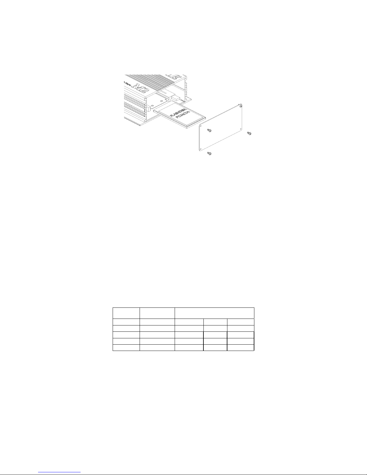
5. Memory Card Removal/Installation:
The M3 utilizes removeable SD memory cards to store audio and configuration information. The image
below illustrates how the card interfaces with the M3. The memory of the M3 is hot swappable and may be
removed or installed without removing power from the system.
5.1. Removal
1. Unscrew the four mounting screws and remove the cover plate to expose the memory card.
2. Depress eject button located directly to the right of the card to unseat the memory.
3. Remove memory card from the M3.
4. Replace cover and secure with the four mounting screws.
5.2. Installation
1. Unscrew the four mounting screws and remove the cover plate to expose the memory card holder.
2. Align the side rails of the memory card so they glide into the black plastic guides of the memory
card holder.
3. Push the card into the holder until the card “clicks in”
5. Replace cover and secure with the four mounting screws.
5.3. Capacity, Data Rates and Part Numbers:
Size Model No. Approx. recording time (Minutes)
Mono / Stereo or Dual Mono
7kHz 15kHz 20kHz
32 64 128
1GB SD-1GB 4164 2082 1041
2GB SD-2GB 8328 4164 2082
4GB SD-4GB 16656 8328 4164
M3 User's Manual V 1.0 Revised 13, Sept 2011 Page 23
Page 24

__________________
__________________
__________________
Return Address
MACKENZIE LABORATORIES, INC.
1163 Nicole Court
Glendora, CA 91740 USA
------------------------------------------------------------------------------------------------------------------
OTHER MACKENZIE PRODUCT LINES
Storecasting & Message On Hold - Mackenzie's full line of digital Storecasting & Message-On-Hold systems, turn your
public address system and telephone into a powerful marketing tool. The DYNAVOX seri es offers maintenance free digital
playback with tape, modem or satellite download. Several varieties are available with advanced features such as Musi cThru, individual message enable/disable, message sequencing and mor e.
Digital Message Repeaters - Mackenzie's line of Digital Message repeaters are the ide al audio announcement solutions for
Public Address, Amusement, Entertainment, Museum and Exhibit applications. Self contained solid state systems offer
unparalleled reliability. A variety of channel, connection, bandwidth and memory configurations are available.
Controls and Peripherals - Many applications require additional equipment to optimize the performance of Mackenzie
products. This area focuses on items developed or sourced for their compatibility, ease of use and value. Included are,
input/output controllers, speakers, amplifiers, motion sensors and pushbuttons among others.
Transit - Mackenzie is making a difference in transit applications with innovative solutions for ADA compliance and
Passenger Information Systems. These products address a variety of audio and text messaging requirements and support
both in-vehicle and wayside installations.
M3 User's Manual V 1.0 Revised 13, Sept 2011 Page 24
 Loading...