

Mach speed MSNV-939 User Manual

MSNV-939
FCC Information and Copyright
This equipment has been tes ted and fou nd to c omply with the limits of a C lass
B digital device, pursuant to Part 15 of the FC C Rules. These limits are designed
to provide reasonable protection against harmful interference in a residential
installation. This equipment generates, uses and can radiate radio frequency
energy and, if not installed and used in accord a nce with the instruction s , may
cause harmful interferen c e to radio c ommu nications. There is no gu aran tee
that interference will not occur in a particular installation.
The vendor makes no re pr es entations or warranties with respect to the
contents here and spec ially disclaims any implied w arranties of mercha ntability
or fitness for any purpose. Further the vendor reserves the right to revise this
publication and to ma ke changes to the contents here without obligation to
notify any party beforehand.
Duplication of this publication, in pa r t or in whole, is not allowe d without first
obtaining the vend or ’ s approval in writing.
The content of this user’s manual is subject to be cha nged without notice and
we will not be responsible for any mistak es foun d in this us er’s manua l. All the
brand and product names are trademarks of their respective companies.
i

Table of Contents
Chapter 1: Introduction.....................................................1
1.1 Motherboard Features.......................................................1
1.2 Package Checklist.............................................................4
1.3 Layout & Components.......................................................5
Chapter 2: Hardware Installation.....................................6
2.1 Central Processing Unit (CPU) .........................................6
2.2 Fan Headers .....................................................................8
2.3 Memory Modules Installation ............................................9
2.4 Connectors & Slots .........................................................11
Chapter 3: Headers & Jumpers Setup........................... 13
3.1 How to setup Jumpers ....................................................13
3.2 Detail Settings.................................................................13
Chapter 4: Useful Help....................................................21
4.1 Award BIOS Beep Code .................................................21
4.2 Extra Information.............................................................21
4.3 Troubleshooting...............................................................23
Chapter 5: WarpSpeeder™............................................. 24
5.1 Introduction......................................................................24
5.2 System Requirement.......................................................24
5.3 Installation.......................................................................25
5.4 [WarpSpeeder™] includes 1 tray icon and 5 panels .......26
ii
CHAPTER 1: INTRODUCTION
1.1 MOTHERBOARD FEATURES
A. Hardware
CPU
Supports Socket 939.
Supports AMD Athlon 64 / Athlon 64 FX /Sempron processors.
Supports Dual Core CPU.
Supports Maximum Front Side Bus up to 2G HT.
AMD 64 architecture enables simultaneous 32 and 64 bit computing.
Supports HyperTransport and AMD Cool’n’Quiet Technologies.
Chipset
NVIDIA nForce4 (NF4-A9 A)/ nForce4 Ultra (NF4 Ultra-A9 A):
- Supports NVIDIA Firewall.
- Supports 10 USB 2.0 ports.
- Supports NVIDIA nTune Utility.
- Supports 1 PCI-Express x16 interface graphics slot.
- Supports 4 SATA ports, each channel up to 1.5Gb/s (NF4-A9 A) /
3.0Gb/s (NF4 Ultra-A9 A).
- Supports 4 IDE disk drives with PIO Mode 5, Bride Mode and Ultra
DMA 33/66/100/133 Bus Master Mode.
- Compliant with AC’97 version2.3 specification.
- Compliant with PCI-Express Version 1.a specification.
MSNV-939
Dimensions
ATX Form Factor: 20.8cm (W) x 29.35cm (L)
Operating Systems
Supports Windows 2000 and Windows XP.
Note: Do not support Windows 98SE and Windows ME.
Main Memory
Supports Dual Channel DDR.
Supports DDR266/333/400.
Maximum memory size is 4GB.
DIMM Socket
Location
DIMM1 128MB/256MB/512MB/1GB *1
DIMM2 128MB/256MB/512MB/1GB *1
DIMM3 128MB/256MB/512MB/1GB *1
DIMM4 128MB/256MB/512MB/1GB *1
DDR Module Total Memory Size
1
Max is 4 GB.

MSNV-939
On-board IDE
2 on-board connectors support 4 IDE disk drives.
Supports PIO mode 0~4.
Supports Ultra DMA 33/66/100/133 bus master mode.
Serial ATA
4 on-board Serial ATA connectors support 4 serial ATA (SATA) ports.
nForce4 Ultra supports SATA 2.0 specification, with data transfer rates
up to 3Gb/s.
nForce4 supports SATA 1.0 specification, with data transfer rates up to
1.5Gb/s.
Slots
Four 32bit PCI bus master slots.
Two PCI-Express x1 slots:
- PCI Express 1.0a compliant.
- Bandwidth 250MB/s per direction.
One PCI-Express x16 slot.
- PCI Express 1.0a compliant.
- Maximum theoretical realized bandwidth of 4GB/s simultaneously
per direction, for an aggregate of 8GB/s totally.
Super I/O
Chip: ITE IT8712F.
Low Pin Count Interface.
Provides the most commonly used legacy Super I/O functionality.
Environment Control initiatives,
- H/W Monitor
- Fan Speed Controller
- ITE's "Smart Guardian" function
On-board AC’97 Audio Sound Codec
Chip: ALC655:
- Compliant with AC’97 version2.3 specification.
- Supports 6 channels audio output.
10/100 LAN PHY
PHY: RTL8201CL.
Half/Full duplex capability.
Supports ACPI, PCI power management.
2
M S N V - 9 3 9
Security
NVIDIA Firewall technology
- Native firewall solution
Advanced features
- Remote access, configuration, monitoring
- Command line interface (CLI)
- WMI scripts.
Internal On-board Connectors and Headers
1 audio-out header supports audio-out facilities.
1 front panel header supports front panel facilities.
1 CD-in connector supports CD-ROM audio-in function.
1 SPDIF-out connector supports digital audio-out function.
1 floppy connector supports 2 FDD devices with 360K, 720K, 1.2M,
1.44M and 2.88Mbytes.
2 IDE connectors support 4 IDE disk drives.
3 USB headers support 6 USB 2.0 ports at front panel.
4 Serial ATA connectors support 4 SATA devices.
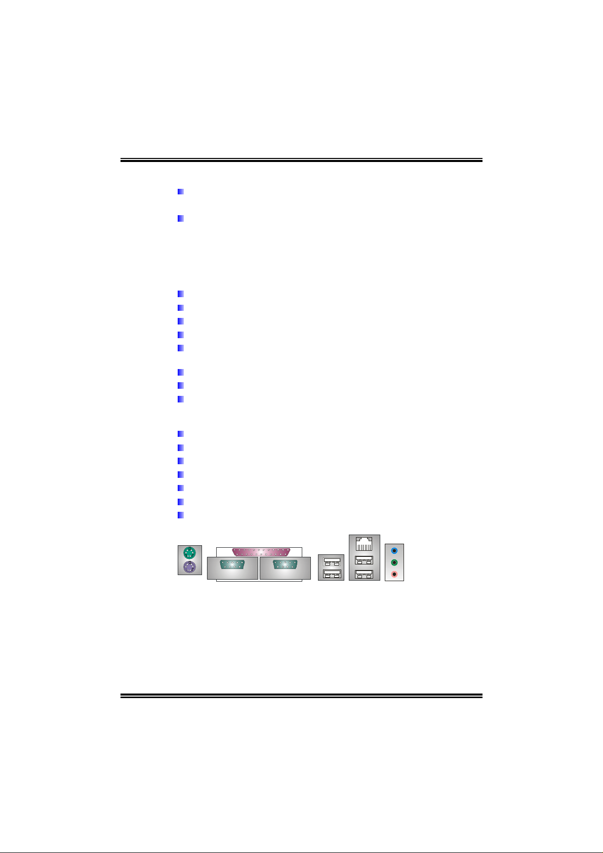
Rear (Back Panel) Side Connectors
1 PS/2 Mouse Port.
1 PS/2 Keyboard Port.
1 Printer Port.
1 Serial Port. (JCOM2 is optional.)
1 RJ-45 LAN jack.
4 USB 2.0 Ports.
3 audio ports support 6 channels audio-out facilities.
PS/2
Mouse
PS/2
Keyboard
COM1
JCOM1
Printer Port
COM2
(optional)
JCOM2
(optional)
JUSB1
USB *2
LAN
Connector
USB *2
Line-in/Rear
Line-out
MIC-in/
Center/
Left
3
M S N V - 9 3 9
B. BIOS & Software
BIOS
Award legal BIOS.
Supports APM1.2.
Supports ACPI.
Supports USB Function.
Bundled Software
Supports 9th Touch™, WINFLASHER™ and FLASHER™.
1.2 PACKAGE CHECKLIST
FDD Cable X 1
HDD Cable X 1
User’s Manual X 1
Serial ATA Cable X 1
Fully Setup Driver CD X 1
Rear I/O Panel for ATX Case X 1
USB 2.0 Cable X1 (optional)
S/PDIF Cable X 1 (optional)
Serial ATA Power Switch Cable X 1 (optional)
4
M SN V- 93 9
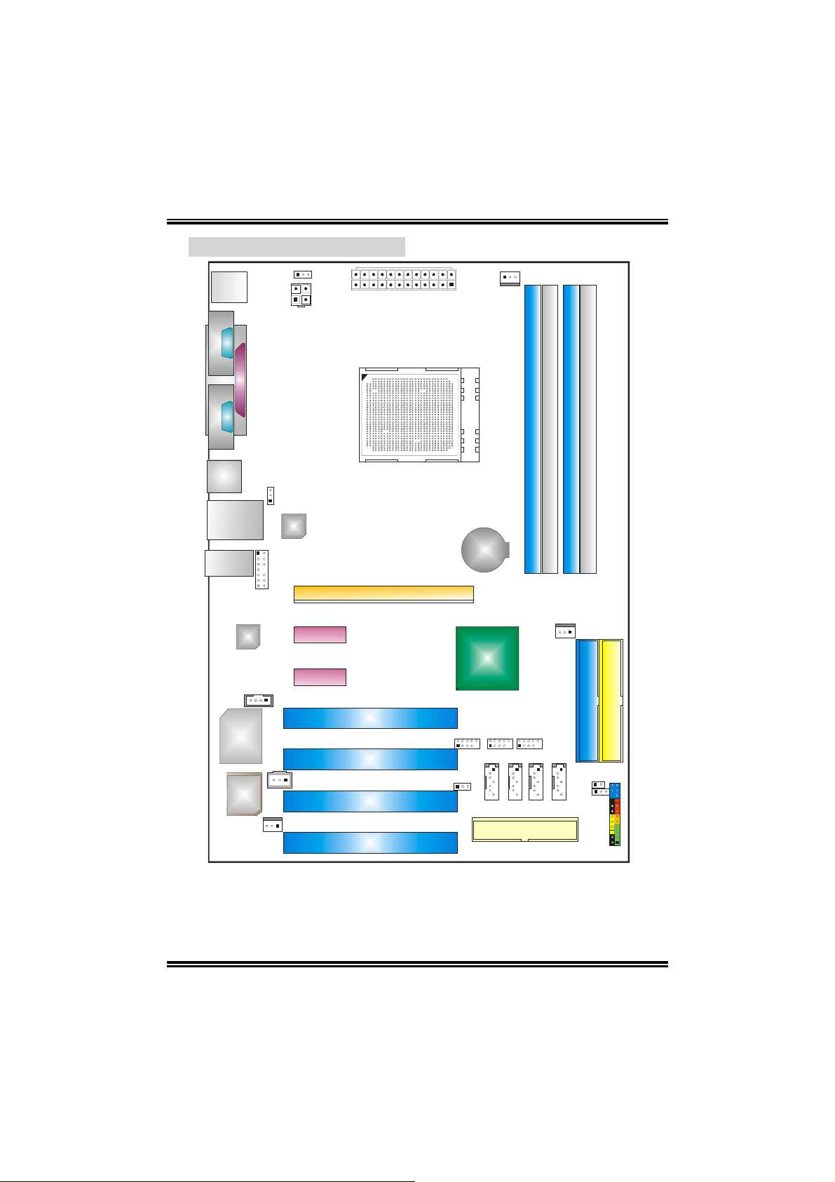
1.3 LAYOUT & COMPONENTS
JKBMSV1
JKBMS1
JCOM1
(optional)
JCOM2
JATXPWR2
JPRNT1
JATXPWR1
JCFAN1
Socket 939
DIMM1
DIMM2
DIMM3
DIMM4
JUSB1
JUSBLAN1
JAUDI O2
Codec
JCDIN1
Supe r I/O
JUSBV1
LAN
JAUDIO1
PEX1_1
PEX1_2
JSPDIF_OUT
BIOS
JSFAN1
Note: ■ represents the 1
st
pin.
PCI1
PCI2
PCI3
PCI4
PEX16
BAT1
nForce4
or
nForce4 Ultra
JUSB3 JUSB4JUSB2
JSATA1
JUSBV2
JSAT A2
FDD1
JSAT A3
JNBFAN1
JSAT A4
IDE1
JCI1
JCMOS1
JPANEL1
IDE2
5
M S N V - 9 3 9
CHAPTER 2: HARDWARE INSTALLATION
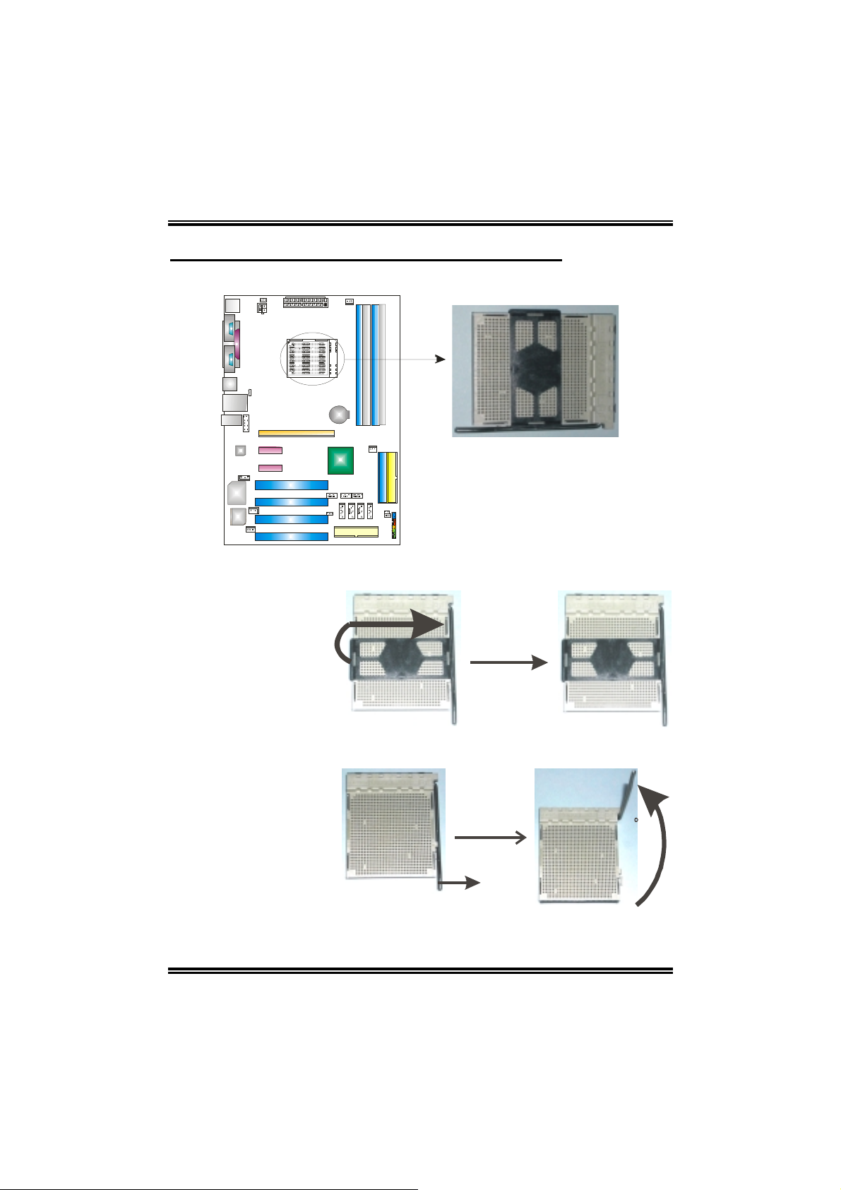
2.1 CENTRAL PROCESSING UNIT (CPU)
Step 1: Remove the socket protection cap.
Step 2: Pull the lever t ow ard directi on A from the socket and then raise the lever up
to a 90-degree angle.
90
A
6
M S N V - 9 3 9
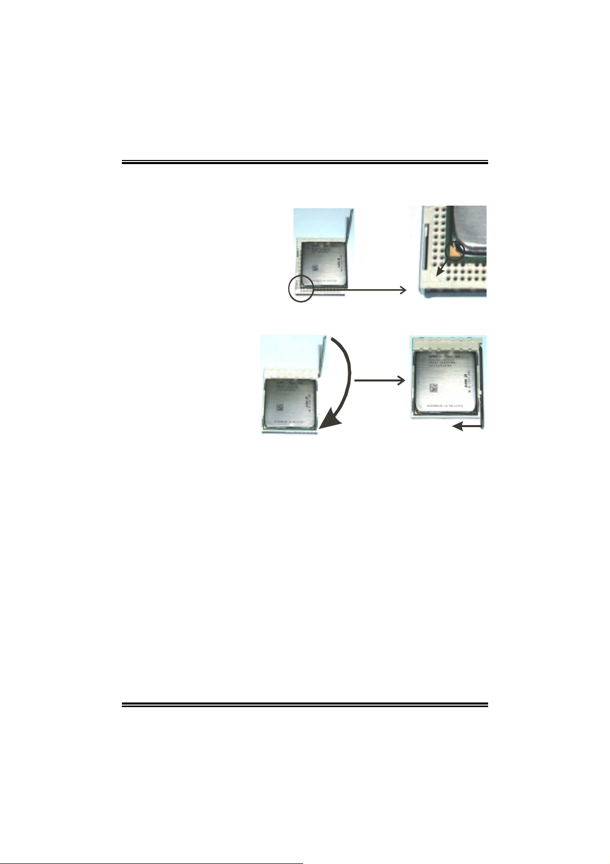
Step 3: Look for the white triangle on socket, and the gold triangle on CPU should
point forwards this white triangle. The CPU will fit only in the correct
orientation.
Step 4: Hold the CPU down firmly, and then close the lever toward direct B to
complete the installation.
B
Step 5: Put the CPU Fan on the CPU and buckle it. Connect the CPU FAN power
cable to the JCFAN1 . T his completes the installat ion.
7
MSNV-939
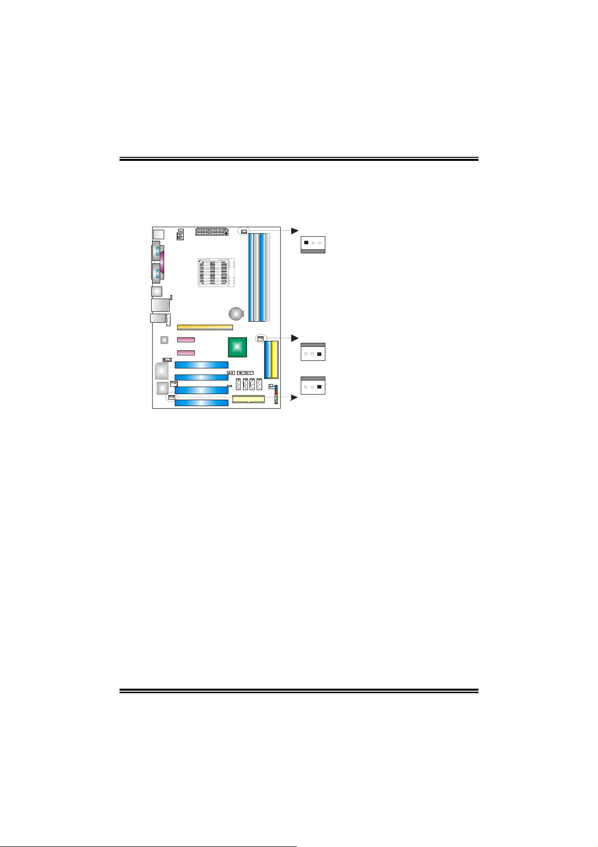
2.2 FAN HEADERS
CPU FAN Power Header: JCFAN1
System Fan Power Header: JSFAN1
Northbridge Fan Power Header: JNBFAN1
JCFAN1
JNBFAN1
13
13
13
Pin Assignment
1 Ground
2 +12V
3 FAN RPM rate sense
(Only for JCFAN1 and
JSFAN1.)
JSFAN1
Note:
The JCFAN1 and JSFAN1 reserve system cooling fan with Smart Fan Control utility. It
supports 3 pin head connector. When connecting with wires onto connectors, please note
that the red wire is the positive and should be connected to pin#2, and the black wire is
Ground and should be connected to GND.
8
MSNV-939
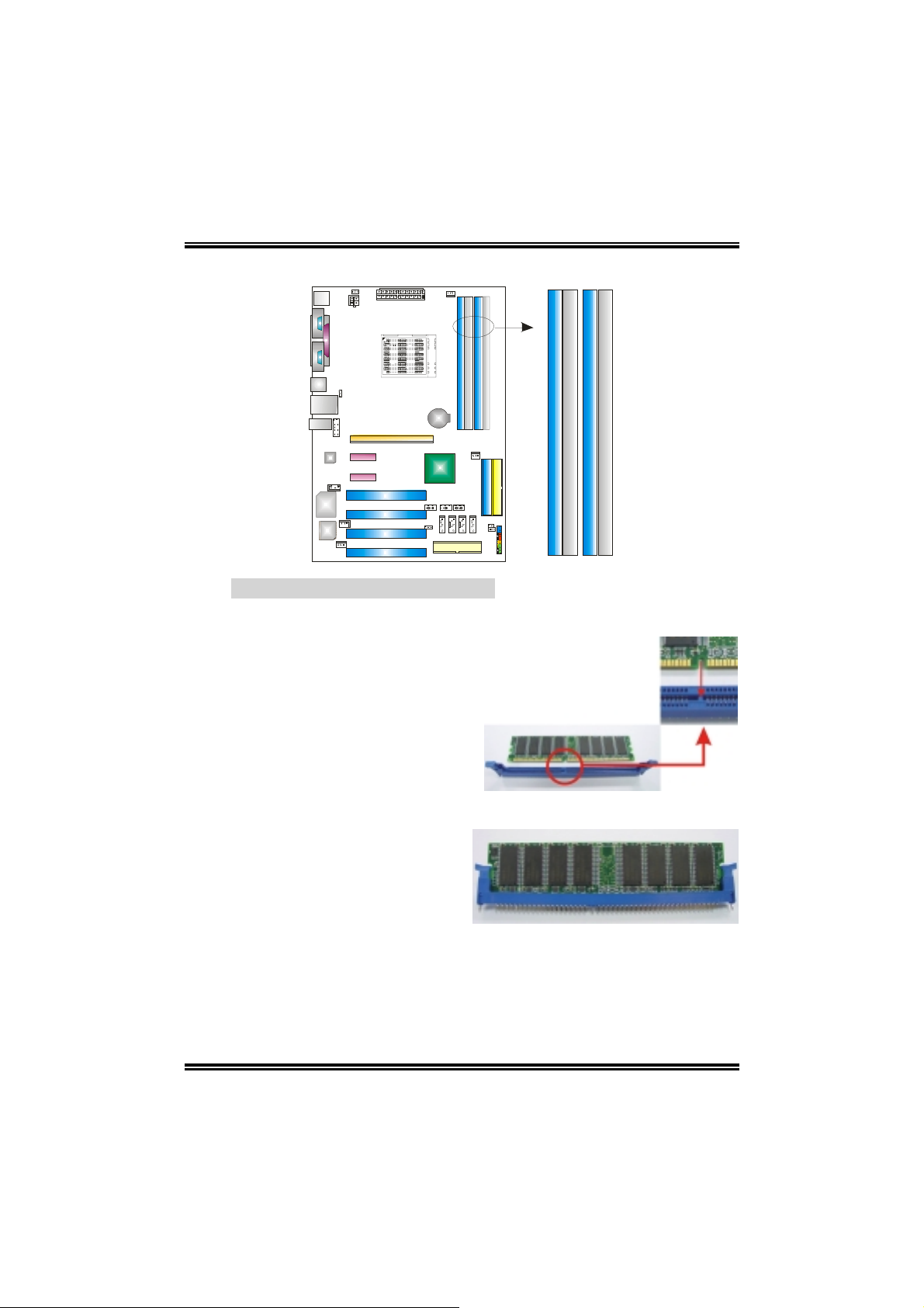
2.3 MEMORY MODULES INSTALLATION
DIMM3
DIMM1
DIMM4
DIMM2
2.3.1 DDR Module installation
1. Unlock a DIMM slot by pressing the retaining clips outward. Align a DIMM on
the slot such that the notch on the DIMM matches the break on the Slot.
2. Insert the DIMM vertically and firmly into the slot until the retaining chip snap
back in place and the DIMM is properly seated.
9
 Loading...