


IN CEILING DUAL BAND ACCESS POINT/ ROUTER 750MBPS
WL-ICDBG24-051
USER MANUAL

REV.240517

3
Thanks
for choosed our product
________________________________
INDEX
General Warning
CHAPTER 1 Hardware and Operation mode Instruction
1.1 LED indicator
1.2 AP Interface
1.3 Power Supply
1.3.1 PoE Adapter Power Supply
1.3.2 Powered by PoE Switch
1.4 Operation Mode
1.4.1 Wirelss AP
1.4.2 Wirelss Repeater
1.4.3 Gateway
1.5 Connect Wireless AP with PC
CHAPTER 2 Login
CHAPTER 3 Quickly Configure Wireless AP
3.1 Gateway Mode
3.2 WiFi Repeater and Station operation configuration
3.3 AP Operation mode
3.4 WISP Operation mode
3.5 Advanced Setting
3.5.1 Device Status
3.5.2 2.4Ghz/5.8Ghz Wireless Setting
3.5.3 Virtural AP
3.5.4 Network setting
3.5.5 Management
3.5.6 Share Internet and Obtain IP address automatically
CHAPTER 4 Trouble Shooting
CHAPTER 5 Declaration of conformity

4

General warnings
• Fasten the AP in the desired position, considering that as the device
being installed is a radio device, the following simple rules must be
observed:
• Avoid enclosing the appliance between two metal walls;
• The efficiency of radio transmission is reduced when there are obsta-
cles, metal shelving or other objects that may block the reception of the
radio signals;
• If the product is wall-mounted, fasten it to a masonry wall rather than
a metal wall, to improve the range of the signal;
• Remember that the best position for the AP is one where it is “visible”
to the other devices. It should be positioned in such a way as to minimi-
ze any obstacles;
• Like all radio equipment, avoid installing the AP near other electronic
appliances so as to avoid interference;
• If the appliance is used in a way that is not described by the manu-
facturer, the specified level of protection may be affected.
• Do not install the instruments in environments with the following
characteristics:
- strong vibrations or knocks;
- exposure to water sprays;
- exposure to direct sunlight or the elements in general;
5

6
CHAPTER 1
HARDWARE AND OPERATION MODE INSTRUCTION
1.1 LED indicator
Green: Power Indicator
Blue: WiFi Indicator
1.2 AP Interface
RST: Reset Button, it make AP revert to default data after press it 15 sec.
WAN: Gigabit WAN Port, connect with ADSL modem or Internet mainly. It
will be LAN port under Wireless AP and WiFi Repeater operation mode
LAN: Gigabit LAN Port to end users
LED: LED Indicator of WAN port and LAN port
DC: DC power connector
1.3 Power Supply
1.3.1 PoE Adapter Power Supply
The connection diagram, internet cable connect to PoE adapter’s LAN Port,
Ceiling AP’s WAN port connect to PoE adapter’s PoE Port, then PC will ac-
cess into ceiling AP through cable or wireless
The PD wireless AP support 24V PoE, so PoE adapter should be 24V PoE.

7
1.3.2 Powered by PoE Switch
The connection diagram, Internet cable from PoE Switch to Ceiling AP’s
WAN Port, then PC access into ceiling AP wired/wireless.
Pls notevthe PD wireless AP support 24V PoE, m the PoE switch should
comply with 24V PoE.
1.4 Operation Mode
There are three operation mode on this wireless AP:
1.4.1 Wirelss AP
Plug&Play to transmit wireless signal for wireless and users from wired
networking.

8
1.4.2 Wirelss Repeater
Wireless receiver and transmit, to extend the existing wireless networ-
king for more range.
1.4.3 Gateway
Supply WAN connection from DSL, Cable MOdem or broadband mobile
phone network through PPPoE, Static, IP, Dynamic IP.

9
1.5 Connect Wireless AP with PC
Use can connect the PC with wireless AP by Wireless SSID and LAN
cable: The diagram of wireless connection showed as follow:
Pls note: the default SSID is MachPower2.4G/MachPower5G, SSID’s
password is 12345678
The diagram of LAN cable connection showed as follow:
CHAPTER 2
LOGIN
1. Connect the Ceiling AP with computer
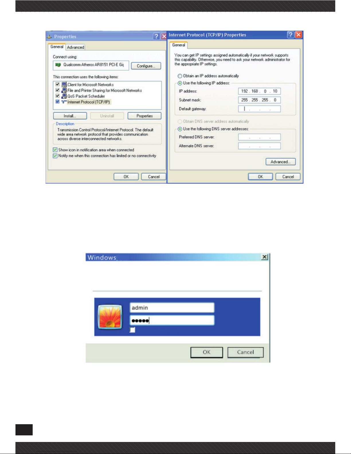
2. Configure the PC
Configure the PC’s local connection IP address as 192.168.0.X (X is num-
ber from 2 to 254), subnet mask is 255.255.255.0, follow the next image.
10
3. Input 192.168.0.253 into IE browser, then pop up the login page, the
default login user name: admin, Passwords: admin, pls do following the
next image
4. After login, then Device Status will be showed;
This page will show the AP’s default operation mode, channel, con-
nection status, CPU usage, Wireless settings, LAN Setting, AP’s Loca-

11
tion, CPE’s hardware/firmware version
CHAPTER 3
QUICKLY CONFIGURE WIRELESS AP
3.1 Gateway Mode
Click “Gateway Mode” under following picture and choose the right WAN
access type, then input the right SSID, Channel, key as like.

12
ù
3.2 WiFi Repeater and Station operation configuration
A. Login the Web management page, click “ Repeater Mode”, then “Scran
AP”
B. Select the AP’s SSID want to bridge, take TEST2.4G for example.
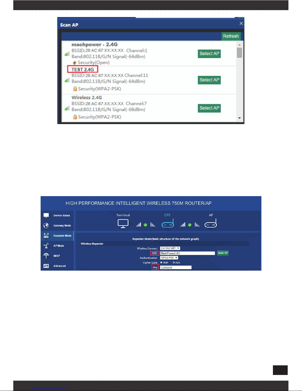
13
If your computer can’t pop up this window, pls check your IE explorer
and see whether it is blocked already. And if this Wireless AP can’t scan
any SSID, pls check if there are 5G wireless signal.
C. input the AP’s key, and apply changes
3.3 AP Operation mode
Choose the AP operation mode, AP Location as well as the wireless
basic settings for the 2.4Ghz and 5.8Ghz,
Then apply;

14
3.4 WISP Operation mode
Click WISP operation mode in Wizard, then will pop up the configure
page, pls set the WISP operation mode based on the stepes showed in
picture:
Then the device were in WISP mode, users can check the details under
status;

15
3.5 Advanced Setting
In advanced setting, user can check the ceiling AP’s firmware version,
working status, 2.4G/5.8Ghz wireless, LAN Status, upgrade firmware,
Reset.
3.5.1 Device Status
This page will show basic parameters for this unit, like firmware ver-
sion,hardware version,etc;
3.5.2 2.4Ghz/5.8Ghz Wireless Setting
On this page, users can configure the basic wireless settings freely
3.5.3 Virtural AP
There are 3 virtural AP in 2.4Ghz and 5.8Ghz individually, (total 6 vir-
tal AP), if need virtural SSID, then users can configure basic settings

16
showed in following picture:
3.5.4 Network setting
In this page, users can set up the basic LAN setting

17
3.5.5 Management
In this part, show the system time, Logs, upgrade firmware, system,
user info.
And we show System time, how to upgrade firmware, as well as Log-in
username/password modification;

18
3.5.6 Share Internet and Obtain IP address automatically
Set computer’s TPC/IP as Obtain an IP address automatically, Obtain
DNS server address automatically as following picture showed. the
computer will obtain the IP address from router or base station to get
Internet.

19
CHAPTER 4
TROUBLE SHOOTING
The Failure phenomenon and solution
Failure phenomenon Solution
SYS Indicator off
Pls make sure the PoE module
connection is right. POE Port connect with AP, LAN port connect
with computer
Can’t land to Wireless AP through
Web page
Pls check the IP address of
computer and Wireless AP to see
whether they are in same networking segment, The method is click
“start”-“Run” “input““cmd”,ping
192.168.0.254 to test the Wireless
AP connectivity.
Reset Wireless AP and load it
again;
Pls make sure the IP address
192.168.0.254 is not occupied
by other device in Wireless AP’s
networking;
Check computer and cable problem, recommend to use 10/100M
UTP unshielded cable;
Clean up Arp binding from “Start”-“Run” input“cmd” arp –d
Clean the IE Brower’s temporary
files and Cache file;

20
Wireless AP can’t connect with AP
(the status display unconnected)
Try to scan the avaliable wireless
networking again;
Make sure the Wireless AP’s wireless standard is correct;
(2.4Ghz signal should connect
2.4Ghz, 5.8Ghz signal should connect 5.8Ghz signal);
The Security and passwords are
matched between Wireless AP
and AP;
The signal strength of AP is too
weak to connect, should be more
than -75dBm;
Can’t scan the wireless AP
Scan it several times more;
If using 5Ghz to scan, please
make sure there are 5G signal
existed.
Reset the Wireless AP, scan it
again after Wireless AP restart;
The connection of Wireless AP
and AP is success, but the computer can’t share internet
Pls Check the computer’s IP
address and DNS setting. If it is
dynamin, set the network card as
automatically obtain. If it is static
IP, pls contact with ISP for correct
IP address and DNS address.
How to Reset Wireless AP
Press the “Reset” button more
than 15 seconds after power on.
The Wireless AP will restore factory default after the Wireless AP
restart.

CHAPTER 5
DECLARATION OF CONFORMITY
RoHS
It is stated that the construction materials used in our pro-
ducts comply with the requirements of Directive 2011/65 /
EU (RoHS).
CE
Declaration of Conformity
Compliance with European Directives
The product complies with the requirements of the Low
Voltage Directive (Safety) 2014/35 / EU and subsequent
amendments.
Disposal of the Product
The product can not be disposed of as urban waste, but it
must be collected separately; Any violation shall be puni-
shable by monetary sanctions in accordance with current
regulations.
Improper disposal of the product, or misuse of the product
itself or parts thereof, is harmful to the environment and to
human health.
Correct disposal of the products bearing the symbol of the
bin marked by a cross helps to avoid possible negative con-
sequences for the environment and human health.
21

22
FCC
This equipment has been tested and found to comply with the
limits for Class B digital devices, pursuant to Part 15 of the FCC
Rules. These limits have been developed to ensure reasonable
protection against harmful interference in domestic installa-
tions. This equipment generates, uses, and can radiate radio
frequency energy. If it is not installed and used in accordance
with the instructions, it may cause harmful interference to radio
communications. It is not excluded that this may also occur in
particular installation types. In the event of interference with
the reception of the radio or television signal, which can be de-
tected by switching the device off and on again, you are invited
to complete one or more of the following procedures:
• Reorient or reposition the receiving antenna.
• Increase the distance between the receiver and the equip-
ment.
• Connect the equipment to a circuit other than the one to whi-
ch the receiver is connected.
• Consult your dealer or an experienced radio / TV technician
for assistance.


24
Mach Power ® is a registered trademark
All Rights Reserved
> visit our website www.machpower.it
 Loading...