

CLOUDING WIRELESS MANAGED
CPE/AP OUTDOOR 5G 900MBPS
WL-CPE5G24-064
USER MANUAL

REV.070617

Thanks
for choosed our product
____________________________________
INDEX
General Warning
CHAPTER 1 Hardware and Operation mode Instruction
1.1 LED indicators
1.2 CPE interface
1.3 Power Supply
1.3.1 Powered by PoE Switch
1.3.2 Connect Outdoor CPE with PC
CHAPTER 2 Log in
CHAPTER 3 WEB GUI interface Setting
3.1 Status
3.2 Wizard Configuration
3.2.1 Gateway Mode
3.2.2 WiFi Repeater mode
3.2.3 WISP Operation mode
3.2.4 AP mode
3.3 Advanced Setting
3.3.1 Device Status
3.3.2 Wireless Setting
3.3.3 Wireless Analizer
3.3.4 Virtual AP
3.3.5 Access Control
3.3.6 Advanced Settings
3.3.7 Network Settings
3.3.8 Management
CHAPTER 4 Share Internet and Obtain IP address automatically
CHAPTER 5 Trouble Shooting
CHAPTER 6 Declaration of Conformity
3

4

General warnings
• Fasten the CPE in the desired position, considering that as the device
being installed is a radio device, the following simple rules must be
observed:
• Avoid enclosing the appliance between two metal walls;
• The efficiency of radio transmission is reduced when there are obstacles, metal shelving or other objects that may block the reception of the
radio signals;
• If the product is wall-mounted, fasten it to a masonry wall rather than a
metal wall, to improve the range of the signal;
• Remember that the best position for the CPE is one where it is “visible”
to the other devices. It should be positioned in such a way as to minimize
any obstacles;
• Like all radio equipment, avoid installing the CPE near other electronic
appliances so as to avoid interference;
• If the appliance is used in a way that is not described by the manufacturer, the specified level of protection may be affected.
• Do not install the instruments in environments with the following
characteristics:
- strong vibrations or knocks;
- If the appliance is used in a manner not specified by the manufacturer,
the protections provided by the appliance may be compromised;
5
CHAPTER 1
HARDWARE AND OPERATION MODE INSTRUCTION
1.1 LED indicators
Green: Power Indicator
Blue: Wi-Fi Indicator
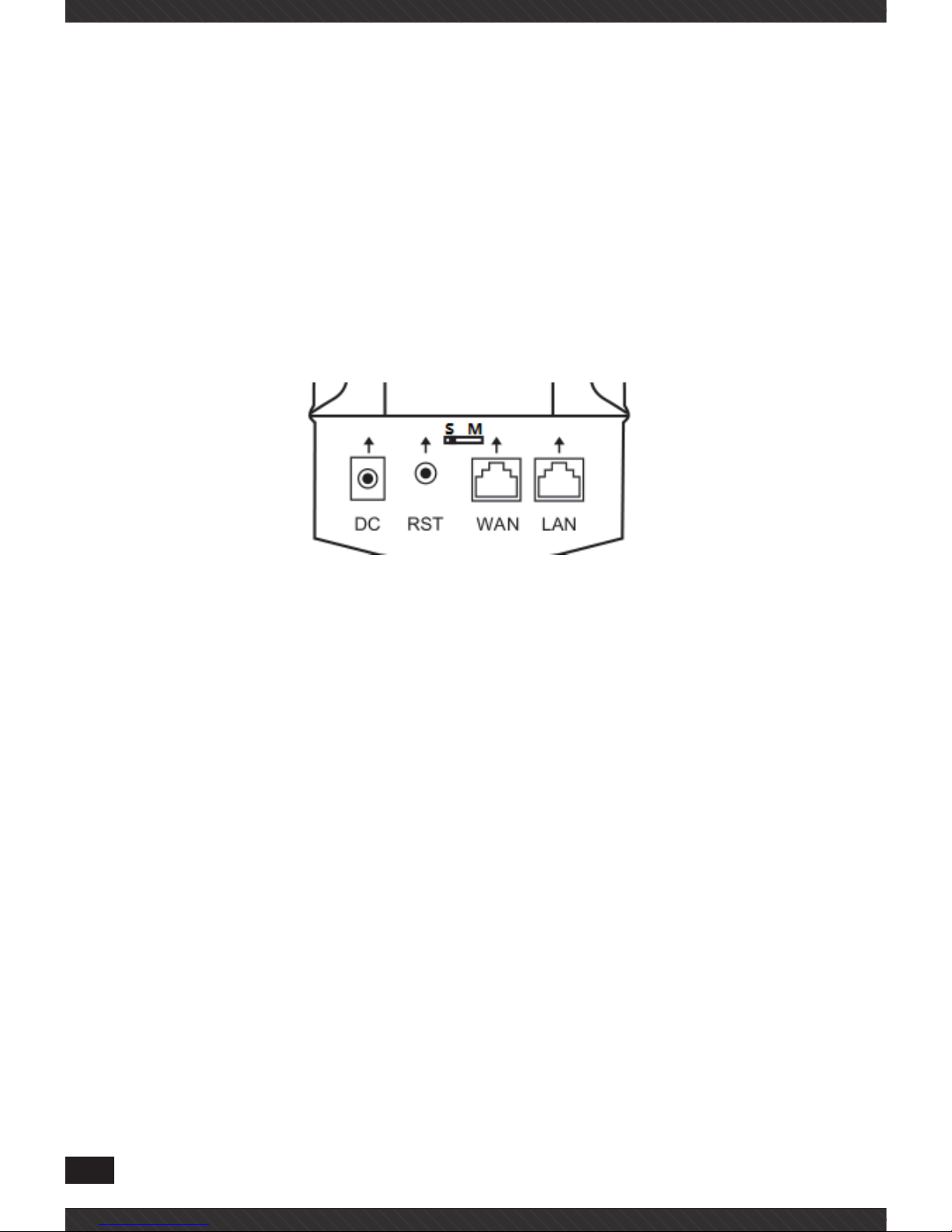
1.2 CPE interface
RST: Reset Button, it make AP revert to default data after press it 15
seconds.
WAN: Gigabit WAN Port, connect with ADSL modem or Internet mainly. It
will be LAN port under Outdoor CPE and WiFi Repeater operation mode
LAN: Fast LAN Port to end users
LED: LED Indicator of WAN port and LAN port
DC: DC power connector
S/M: In WDS working mode, If master CPE, then the button should be in
M side; If Slave CPE, then the button should be in S side. PS. Reset it to
do the WDS Connection.
1.3 Power Supply
1.3.1 Powered by PoE Switch
The connection diagram shows as image1, Internet cable from PoE
Switch to Outdoor CPE’s WAN Port, then PC access into Outdoor CPE
wired/wireless.
Please note: the outdoor CPE support IEEE 802.3at PoE, the switch
6
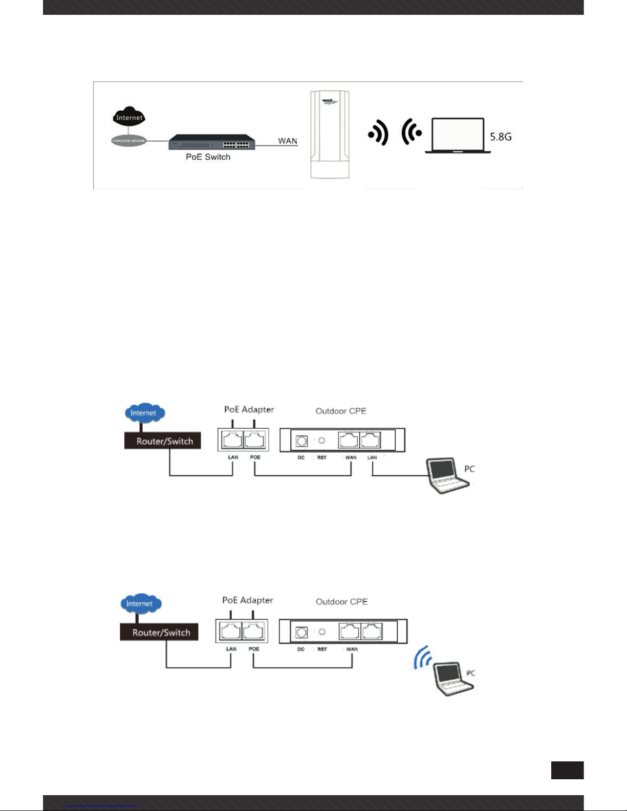
should comply with IEEE 802.3at PoE standard.
image1
1.3.2 Connect Outdoor CPE with PC
Use can connect the PC with Outdoor CPE by Wireless SSID and LAN
cable:
The diagram of wireless connection showed as follow:
Please note: the default SSID is MachPower5G, SSID password is The
diagram of LAN cable connection showed as follow:
The diagram of LAN cable connection showed as follow:
images2
7
8
CHAPTER 2
LOGIN
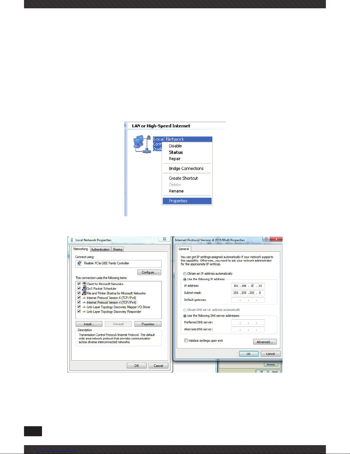
1. Connect the Outdoor CPE with computer
2. Configure the PC’s local connection IP address as 192.168.0.X (X is
number from 2 to 254), subnet mask is 255.255.255.0, follow image3
and image4 to finish.
image3
image4

9
3. Input 192.168.0.254 into IE browser, then pop up the login page, the
default login (please do following image5)
User name: admin
Passwords: admin
image5
CHAPTER 3
WEB GUI INTERFACE SETTING
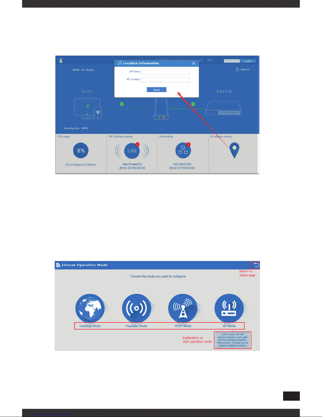
3.1 Status
After login, then image6 Device Status will be showed:
image6

10
In this Outdoor CPE, the default operation mode is AP mode.
Then in 5.8G Wireless Setting, GUI configuration page showed as below:
User can configure the SSID, password, band width, channel here, then
Apply to finish
image7
LAN Setting to configure the DHCP or Fix IP
image8
11
AP location setting: can mark where the AP set up, and AP name as
image9
image9
3.2 Wizard Configuration
Click Wizard in Status page, will pop up following page to configure the
operation mode:
There are four operation mode of this Outdoor CPE, and there are explanation for each operation mode for better application.
image10

12
3.2.1 Gateway Mode
Click Gateway mode, will pop up following pictures:
Please choose the right WAN setting mode, then click next to continue
image11
image12
When click Next, then will complete the Gateway mode setting and show
following picture:

13
image13
When return to Status, the page showed as follow:
image14

14
3.2.2 WiFi Repeater mode
Click WiFi Repeater operation mode in Wizard, then following page will
pop up, and choose the right SSID to bridge, then next.
image15
After click Next button, then should configure the wireless setting as follow, then click Next to finish: data in this page if required
image16
15
Please note: when click wireless relay setting, following page will pop up,
you can make change from here easy
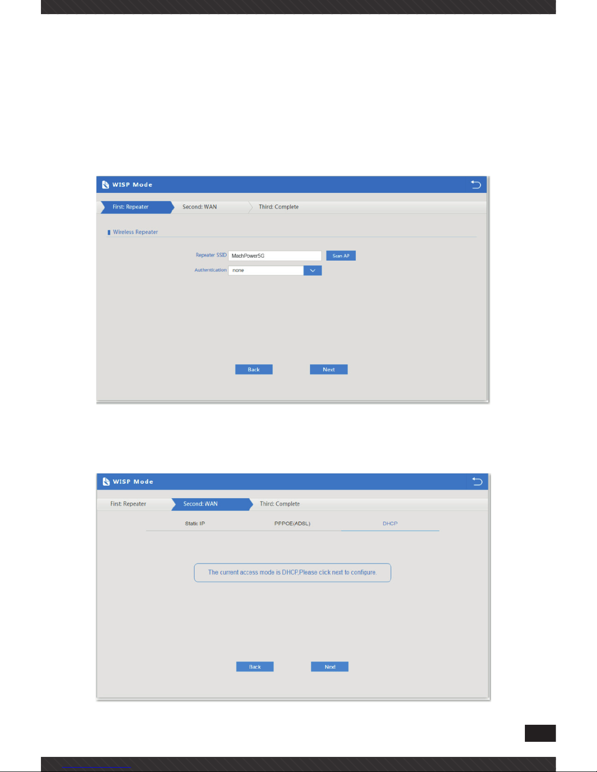
3.2.3 WISP Operation mode
Click WISP operation mode in Wizard, then will pop up the configure page,
pls set the WISP operation mode based on the steps showed in image17
image17
Configure the right WAN setting in WISP operation mode, then next
image18
16
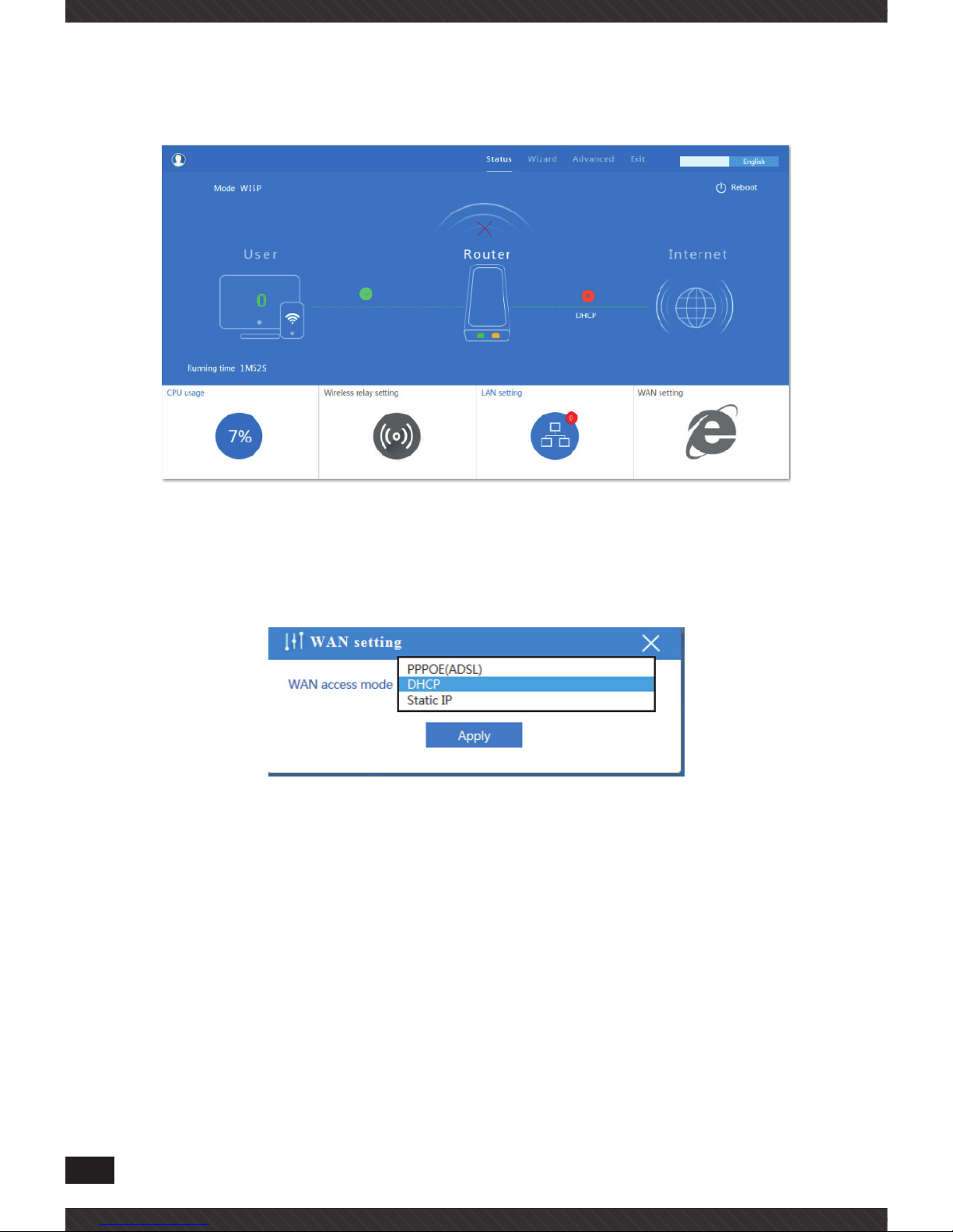
Then complete and back to status, will show the connection fail or success, then can configure the data based on request:
image19
Remark: When click WAN Setting, will pop up following picture:
image20
3.2.4 AP mode
Set the wireless data, AP Location info as required, then click next to continue and enter into LAN setting.
After LAN setting, complete the AP mode configuration and back to Status:

17
image21
image22
image23
18
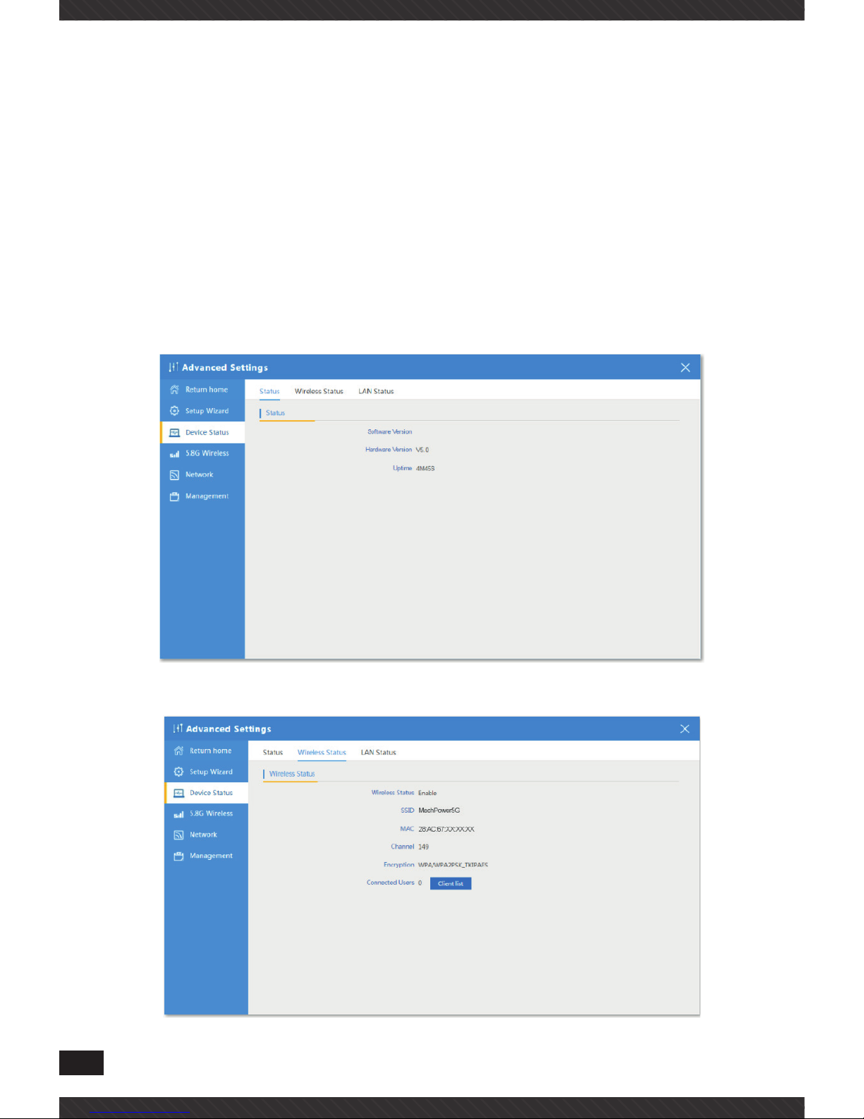
3.3 Advanced Setting
In advanced setting, user can check the Outdoor CPE’s firmware version,
working status, Wireless Status, LAN Status, Upgrade firmware, Reset.
Let’s Click Advanced Setting in status page, will show return home, Setup
Wizard which we showed before. Let’s shown mode in Device Status, Wireless, Network and Management.
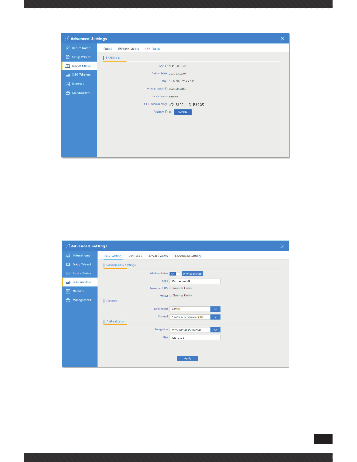
3.3.1 Device Status
In this page, mainly to check the Outdoor CPE’s status in firmware version, Wireless and LAN status
image24
image25
19
image26
3.3.2 Wireless Setting
In this part, will show the Wireless Basic Setting, Virtual AP, Access control and Advanced Setting:
image27
20
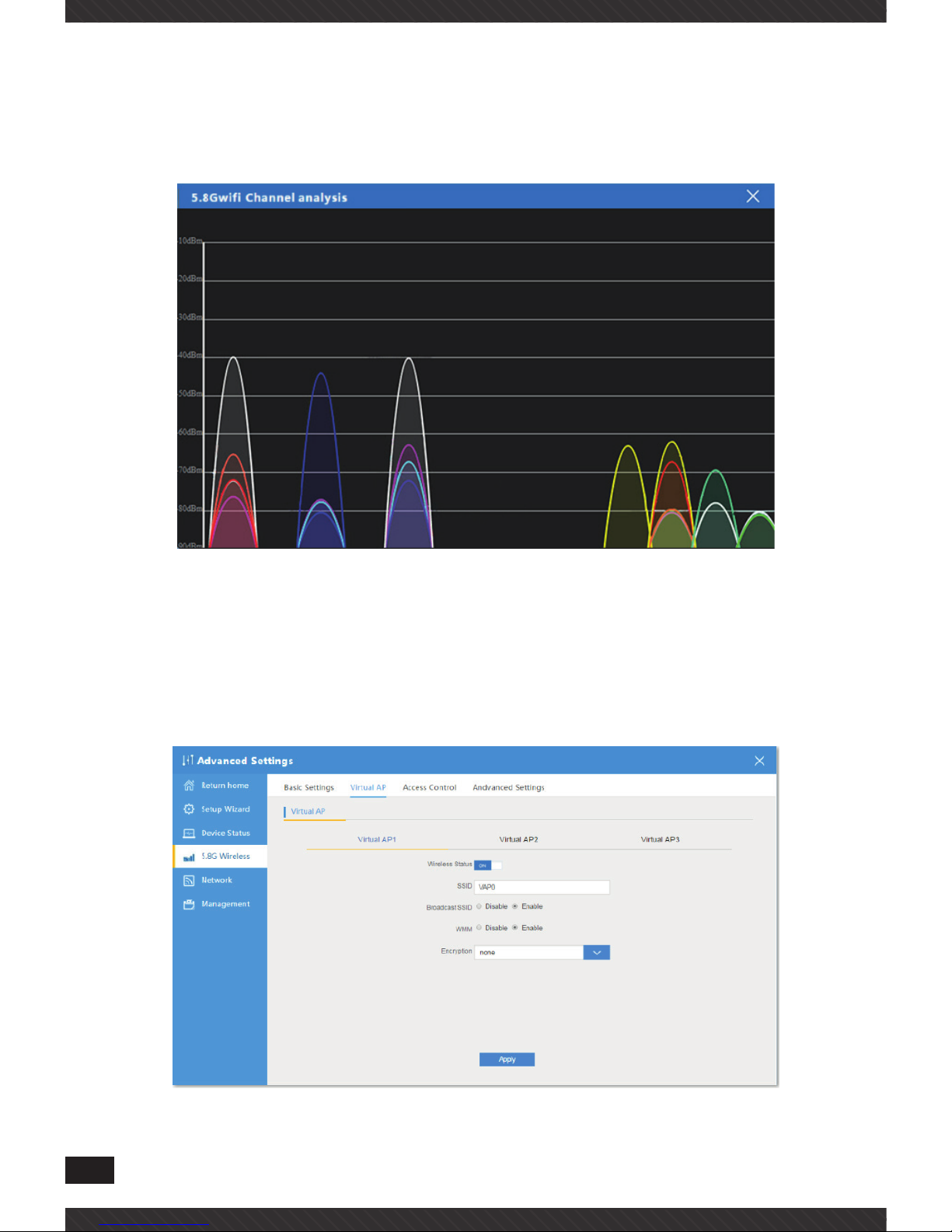
3.3.3 Wireless Analizer
In this part, will show the Wireless Basic Setting, Virtual AP, Access control and and avoid the wifi interface:
image28
3.3.4 Virtual AP
There are 3 virtual AP, if need virtual SSID, then users can configure it
showed in following picture:
image29

21
3.3.5 Access Control
Mainly show MAC allow or deny
image30
3.3.6 Advanced Settings
In this page, will show the regional, RF Power, Max user access.
image31

22
3.3.7 Network Settings
In this page, mainly to show the LAN setting and VLAN as follow:
image32
image33
3.3.8 Management
In this part, show the system time, Logs, upgrade firmware, system, user
info. And we show System time, how to upgrade firmware and system
page to users:

23
image34
image35
image36

24
CHAPTER 4
SHARE INTERNET AND OBTAIN IP ADDRESS
AUTOMATICALLY
Set computer’s TPC/IP as Obtain an IP address automatically, Obtain DNS
server address automatically as following picture showed.
the computer will obtain the IP address from router or base station to
get Internet.
image37

25
CHAPTER 5
TROUBLE SHOOTING
The Failure phenomenon and solution
Failure
phenomenon
Solution
SYS Indicator off
Please make sure the PoE module connection is right.
PoE Port connect with AP, LAN port connect with
computer
Can’t land to Outdoor
CPE through Web page
Please check the IP address of computer and Wireless
AP to see whether they are in same networking
segment, The method is click “start”-“Run” “input““cmd”,ping 192.168.0.254 to test the Wireless AP
connectivity.
Reset Wireless AP and load it again;
Please make sure the IP address 192.168.0.254 is not
occupied by other device in Wireless AP’s networking;
Check computer and cable problem, recommend to use
10/100M UTP unshielded cable;
Clean up Arp binding from “Start”-“Run” input“cmd”
arp –d
Clean the IE Brower’s temporary files and Cache file;
Outdoor CPE can’t
connect with AP
(the status display
unconnected)
Try to scan the avaliable wireless networking again;
Make sure the Outdoor CPE’s wireless standard (11b/
g/n, 2.4G) is correct;
The Security and passwords are matched between
Outdoor CPE and AP;
The signal strength of AP is too weak to connect, should
be more than -75dBm;
Can’t scan the Outdoor
CPE
Scan it several times more;
Make sure there are 5G signal existed.
Reset the Outdoor CPE, scan it again after Outdoor
CPE restart;

26
The connection of
Outdoor CPE and AP
is success, but the
computer can’t share
internet
Pls Check the computer’s IP address and DNS setting.
If it is dynamin, set the network card as automatically
obtain. If it is static IP, pls contact with ISP for correct IP
address and DNS address.
How to Reset Outdoor
CPE
Press the “Reset” button more than 15 seconds after
power on. The Outdoor CPE will restore factory default
after the Outdoor CPE restart.

27
CHAPTER 6
DECLARATION OF CONFORMITY
RoHS
It is stated that the construction materials used in our products
comply with the requirements of Directive 2011/65 / EU (RoHS).
CE
Declaration of Conformity
Compliance with European Directives
The product complies with the requirements of the Low Voltage
Directive (Safety) 2014/35 / EU and subsequent amendments.
Disposal of the Product
The product can not be disposed of as urban waste, but it must
be collected separately; Any violation shall be punishable by
monetary sanctions in accordance with current regulations.
Improper disposal of the product, or misuse of the product
itself or parts thereof, is harmful to the environment and to
human health.
Correct disposal of the products bearing the symbol of the bin
marked by a cross helps to avoid possible negative consequences for the environment and human health.
FCC
This equipment has been tested and found to comply with the
limits for Class B digital devices, pursuant to Part 15 of the FCC
Rules. These limits have been developed to ensure reasonable
protection against harmful interference in domestic installations. This equipment generates, uses, and can radiate radio
frequency energy. If it is not installed and used in accordance
with the instructions, it may cause harmful interference to radio communications. It is not excluded that this may also occur

28
in particular installation types. In the event of interference with the reception of the radio or television signal, which can be detected by switching
the device off and on again, you are invited to complete one or more of the
following procedures:
• Reorient or reposition the receiving antenna.
• Increase the distance between the receiver and the equipment.
• Connect the equipment to a circuit other than the one to which the receiver is connected.
• Consult your dealer or an experienced radio / TV technician for assistance.


Mach Power ® is a registered trademark
All Rights Reserved
> visit our website www.machpower.it
 Loading...