

Page 1

CNC Control with Mitsubishi Drives
and Servo Motors Setup Guide
X15-350-04
2007
Page 2

Page 3

Mach Motion
MachMotion
X15-350-04
CNC Control with:
Mitsubisi Drives
Mitsubisi Motors
24V Power Supply
IO6 Breakout Board
Mounting Arm
Setup Guide
Page 4

Page 5

Page 6

MachMotion.com
[email protected]
Mount arm base on a level
and flat surface. (Figure 1)
6
Slide the vertical square
tubing onto base, and make
a mark at the desired arm
height. Cut tubing on line
with a metal chop-saw or
band-saw. (Figure 2)
(Figure 1)
(Figure 2)
Hold the 2 90° plates on the
(Figure 3)
vertical square tubing. Insert 4
bolts into the 2 90° plates and
only hand tighten. (Figure 3)
When finished, make sure this
bolt is still above the vertical
square tubing. (Figure 3)
Page 7

Mach Motion
Place the square leveling
plate with the set-screws
behind the bolt. (Figure 4)
Now lightly tighten these 3
bolts with a wrench.
7
square level-
ing plate
(Figure 4)
Insert the tree remaining bolts
(Figure 5)
Place the round metal disc
down the CNC Control, with
the two tabs closer to the
rear of the Control.
(Figure 6)
and hand tighten. (Figure 5)
Cut the horizontal square tubing
to desired length. (Just like we
did with the vertical square tubing
in figure 2).
(Figure 6)
Page 8

MachMotion.com
[email protected]
Stack the round plastic disc
on top of the metal disc
with the grooves facing upward. Set the O-ring in
groove of the plastic disc.
(Figure 7)
8
(Figure 7)
Set one of the plastic half
moon rings down with a
metal one on top and
lightly screw down.
(Figure 8)
Slide the horizontal square
tubing flange under the
plastic and metal half moon
rings which were installed
(Figure 8)
(Figure 9)
in figure 8 above.
(Figure 9)
Page 9

Mach Motion
Screw the other to half
moon ring down, and
tighten the screws until
they are snug. (Figure 10)
Take the whole panel and
9
(Figure 10)
arm (horizontal square tubing) and slide into the top
of the 2 90° plates as
shown in figures 11 and
12.
Level the arm by using the
leveling plate. Just tighten
the two set-screws evenly
until the arm is level
(Figure 12)
(Figure 11)
(Figure 12)
Page 10

MachMotion.com
[email protected]
Route all your wires and
cables through the arm.
(Figure 13)
10
(Figure 13)
(Figure 14)
Mount the small cable
cover by installing the 2
small screws in the back
and the 3” screw on the
Slide the cable cover in between the 2 90°
plates starting at the top front bolt and
working your way down the back, tightening the bolts as you go. As shown in fig-
(Figure 15)
(Figure 16)
round end of cover.
(Figure 16)
Page 11

Page 12

MachMotion.com
[email protected]
1. Mount Mitsubishi Drives and 24V Power Supply to machine in a electrical box.
(Electrical Box not Included)
12
2. Mount Mitsubishi Brushless Servo Motors to machine.
Page 13

Mach Motion
13
3. Route and connect motor drive cables
to drives and motors.
Motor Drive Cables
Motor Data Cable
Motor Power Cable
4. Route drive control cables from CNC Control
through the arm to the drives and connect to
the drive in by plugging the drive control cable into
the S/D port.
**** Warning *****
Plug the drive control cable into the S/D
port only!
Drive Control Cable
Page 14

MachMotion.com
[email protected]
5. Connect the drive control cables to the CNC control.
Y Axis Drive
Control Cable
14
Axis 2
Axis 1
Axis 3 Axis 5
Axis 4
Axis 6
Spindle
Control
Spindle
Encoder
Page 15

Mach Motion
6. Wire all limit switches and solid state relays to the breakout board which is in the
back of the CNC control. There are more diagrams on the following pages.
15
Page 16

Mach Motion
To enable the limit switches in Mach3 go to Config / Ports&Pins / Input Signals.
See Example below.
16
Page 17

Mach Motion
5v DC While Charge
Charger Pump Signal
Relays R2-R9 Can be Configured in Mach to be N.O.
Power for Board
pump is Enabled
Spindle Control
Relays
0-10v Spindle
Control
Index (Spindle
Feedback)
Relay Out-put Configuration
(Standard Configuration)
GND
5v
GND
12v
GND
Relay contacts are closed while
charge pump is enabled
EN
GND
17
CP
CP
24VAC?
R2
+R2
R3
+R3
R4
+R4
Neutral
R5
+R5
R6
+R6
R7
+R7
R8
+R8
R9
+R9
CC
CCW
CW
CW
GND
AO
GND
IDX
17
Contactor
Relay Coil
Page 18

Mach Motion
Power for Board
5v DC While Charge
pump is Enabled
Charger Pump Signal
Spindle Control Re-
Relay
+12v DC
lays
0-10v Spindle
Control
Relay Input Configuration
GND
5v
GND
12v
GND
Relay contacts are closed while
charge pump is enabled
EN
GND
17
Limit Switch
CP
CP
R2
+R2
R3
+R3
R4
+R4
R5
+R5
R6
+R6
R7
+R7
R8
+R8
R9
+R9
CC
CCW
CW
CW
GND
AO
GND
IDX
18
Index (Spindle
Page 19

Mach Motion
Pin 14
Parallel
Port Pin #
18-25 GND
Parallel Port Pin-outs
Pin 1
1 Output Axis 6 Direction
2 Output Axis 1 Direction
3 Output Axis 1 Step
4 Output Axis 2 Direction
5 Output Axis 2 Step
6 Output Axis 3 Direction
7 Output Axis 3 Step
8 Output Axis 4 Direction
9 Output Axis 4 Step
10 Input Drive Error Input
11 Input 5-12v Input
12 Input 5-12v Input
13 Input 5-12v Input
14 Output Axis 5 Direction
15 Input 5-12v Input
16 Output Axis 5 Step
17 Output Axis 6 Step
26 5V DC
Parallel Port 1
Direction
(relative to
the PC) Function
Pin 26
Pin 13
Pin 14
Pin 1
Parallel
Port Pin #
1 Output 0-10V Spindle Ctrl
2 Output/Input R2 Relay
3 Output/Input R3 Relay
4 Output/Input R4 Relay
5 Output/Input R5 Relay
6 Output/Input R6 Relay
7 Output/Input R7 Relay
8 Output/Input R8 Relay
9 Output/Input R9 Relay
10 Input 5-12v Input
11 Input 5-12v Input
12 Input 5-12v Input
13 Input 5-12v Input
14 Output CW Spindle Relay
15 Input 5-12v Input
16 Output CCW Spindle Relay
17 Output Charge-Pump
18-25 GND
26 5V DC
Parallel Port
Direction
(relative to
the PC) Function
Pin 26
Pin 13
19
Page 20

Mach Motion
7. Connect drive power to servo drive and wire in Brake Resistor.
20
Power
Connector
240 VAC
U
V
W
P
Break Resistor
C
Break Resistor
D
240 VAC POWER
L1
240 VAC POWER
L2
L3
3 PHASE
U
V
W
P
Break Resistor
C
Break Resistor
D
L1
L1 POWER
L2
L2 POWER
L3
L3 POWER
Page 21

Mach Motion
8. Wire 24V from the 24V Power Supply to all drives.
24+ 24-
24+
24-
21
9. Wire 115V Power into 24V
Power Supply
Neutral
115V
GND
Page 22
Mach Motion
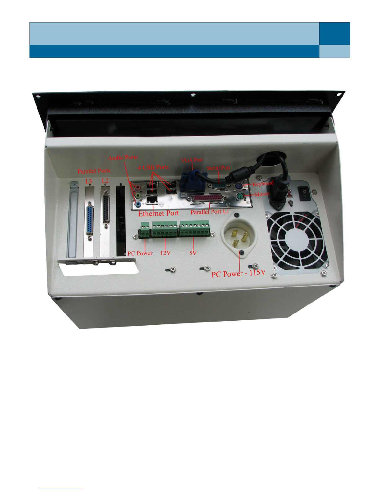
10. Route power cord (standard extension cord) and plug into CNC control.
22
11. Place cover back on CNC Control
12. Turn on CNC control and test motors.
For more details on the I06 Breakout Board refer to the MachMotion I06 Motion Control Manual. For
more details on Mach3 Control Software please refer to the Mach3 User Manual. You can find both of
these manuals and other manuals in a folder on the desktop of your new CNC Control or you can
download them off of MachMotion.com
Page 23

Mach Motion
Notes:
23
Page 24

14518 County Road 7240
Newburg, MO 65550
E-mail: [email protected]
[email protected]
Website: MachMotion.com
 Loading...