


The primary way to power the control is wit h the key.
Figure 1 – Keys
Place one key into the keyhole at t he back right hand side of the cont rol as pictured below. Turn on the control by
rotating the key and then quickly releasing it.
X15-250 User Manual
1 Turning on the control
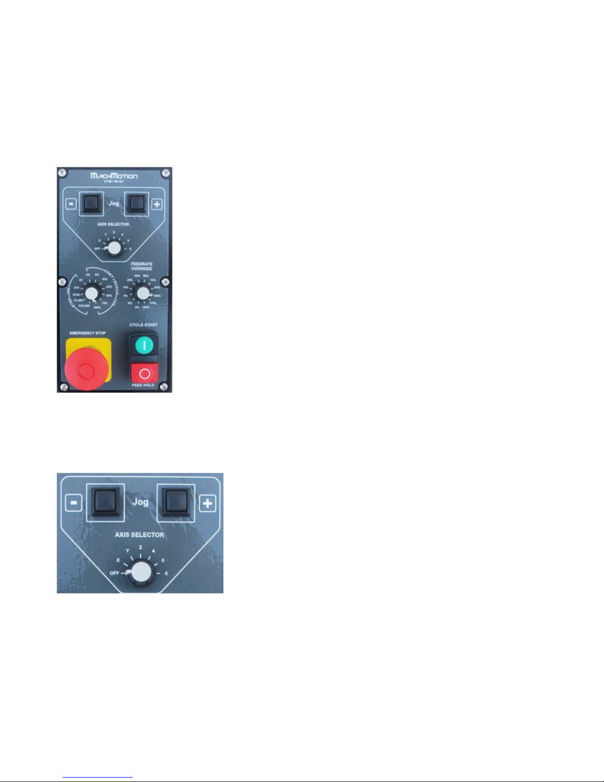
Figure 2 – PC Start
There is also a small black backup power on butt on near the power plug behind t he back panel of t he control. See Figure
15 - Control Port Diagram.
2.1 Operator Panel (X15-10-01)
On t he right hand side of your control there is the operator panel with jog buttons, select or knobs, and a few butt ons
(See Figure 3).
Figure 3 – Operator Panel
The jog but t ons can be used to move the axes manually. Use t he Axis Select or to choose which axis t o jog. If the Axis
Select or is in the of f position, the jog buttons are disabled (See Figure 4).
Figure 4 – Jog Butt ons and Axis Selector
Note: If the jog buttons do not work, make sure that the Axis Selector on the optional pendant is turned off.
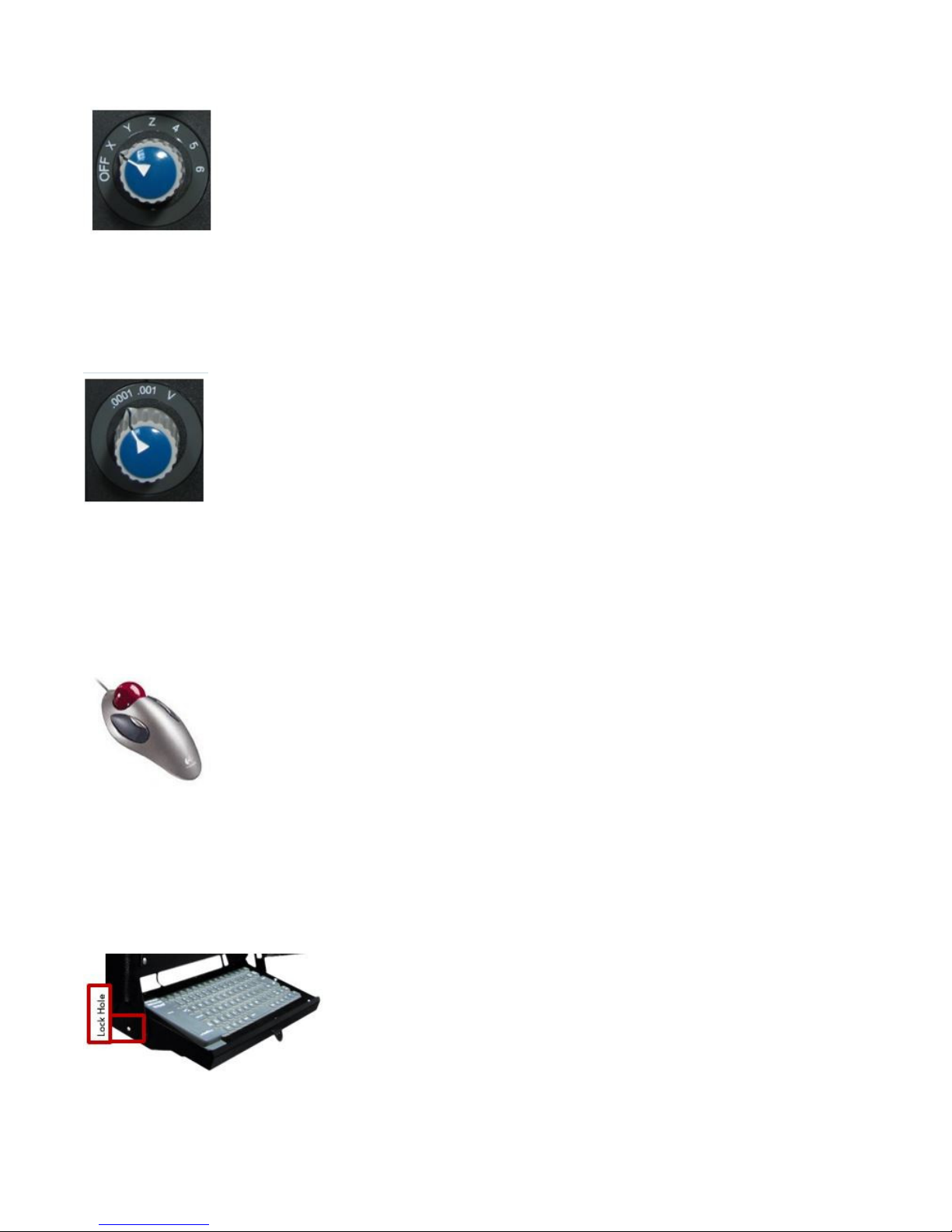
To change the jogging speed or the jog increment s adjust the Jog Selector. The select ions labeled Step Jo g control
which predef ined step or increment t he syst em moves each t ime a jog key is press ed. The system can jog 1 t hrough
10,000 10,000t hs of a unit by selecting X1 t hrough X10,000. See Figure 5 below.
2 Control Components
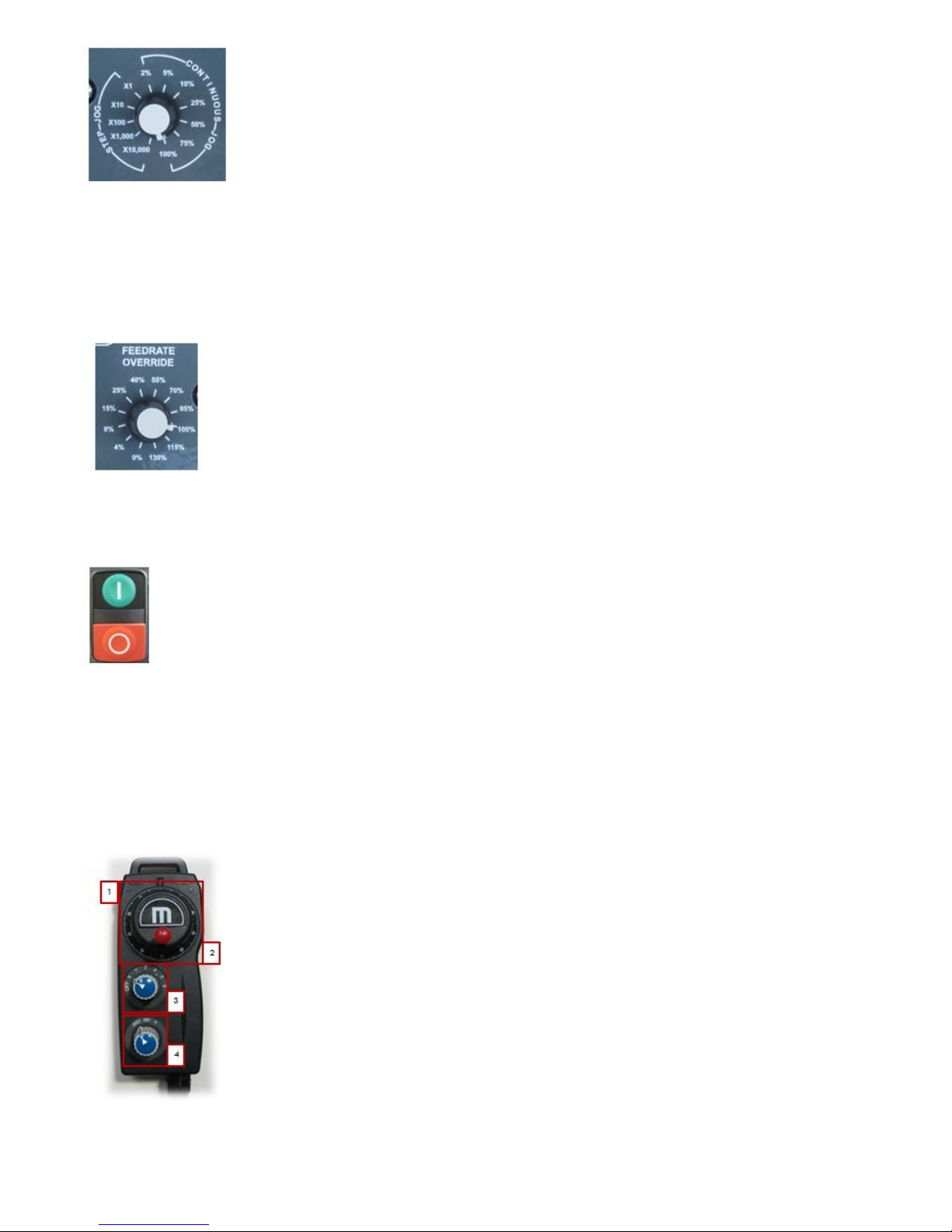
Figure 5 – Jog Select or
To jog continuously rat her than increment ally, turn the Jog Selector over into t he Continuo us Jog sect ion. The machine
can jog at t he full jog rate (100%) or slow it down to 2%.
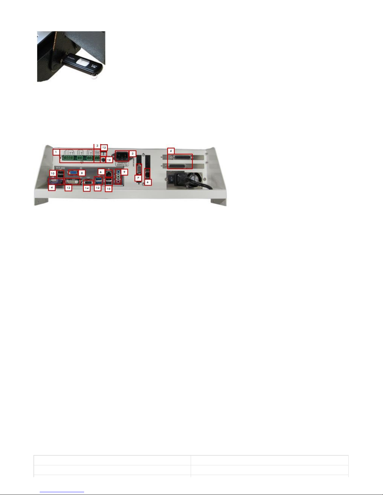
The Feedrat e Selector can adjust the feed rate override from 0% all t he way to 130%. It can be used t o slow t he
machine while running a program. Also, in st ep jog mode the speed of t he axis is regulated by the feed rate Selector.
Figure 6 - Feedrate Selector
The green button is a cycle start butt on which st arts a file and t he small red butt on is a feed hold which pauses t he file.
Figure 7 - Cycle St art and Feed Hold Butt ons
The red E-Stop button stops the whole syst em and prevents any movement .
2.2 Pendant (X15-20-01, Optional)
The pendant is mounted on t he right side of t he control near the operator panel. See Figure 8 below.
Figure 8 - Pendent
To use t he pendant switch t he Axis Selector (3) to the desired axis. The pendant will not work if the Axis Selector is in
the OFF posit ion. While holding down the enable butt on (see Figure 9, 1), rotate the hand wheel (2, also called t he MPG)
and the select ed axis will move. Change axes by swit ching the Axis Select or to a different axis. The speed can be
adjust ed using the Jog Selector (4).
Figure 9 - Axis Select or
The Jog Selector on t he pendant switches bet ween either 0.0001 or 0.001 unit increments. Each click of the MPG will
move the select ed increment. However, if the Jog Select or is on V t hen the MPG is in velocit y mode. In velocity mode
the axis moves as long as t he MPG is turning and the speed of the axis is regulated by the speed of the hand wheel. In
ot her words, t urning the hand wheel very fast will make the axis move very quickly.
Figure 10 - Jog Select or
When t he pendant is not in use, make sure to turn t he Axis Selector to OFF. Otherwise the operator panel jog
functionality will be disabled.
2.3 Mouse
Below t he operator panel is a ball mouse. Use this for navigating around on the control.
Figure 11 - Mouse
2.4 Keyboard
The keyboard is located at the bot t om of t he control in a flip-out t ray. For security and safet y reasons there is a lock
hole in the back left hand side of t he keyboard tray t o prevent the tray from opening. The lock is not supplied with the
control.
Figure 12 - Keyboard
2.5 External USB Port
On t he right side of t he keyboard there is a USB port. Use t his for transferring programs, files, or any other data to and
from t he control.
Figure 13 - USB Port
Below is a diagram of all the different ports on the control wit h a brief descript ion of each.
Figure 14 - Control Port Diagram
1. Power Board
Three power supplies (24VDC, 12VDC, & 5VDC) for low power applications.
2. Po wer Cable
110VAC-220VAC power for the control.
3. PC St art
To remot ely st art t he control connect these t wo pins t oget her with a momentary push butt on switch.
4. PS2 P o rt wit h USB Convert er
This is used f or the mouse.
5. Parallel Po rt s (O pt io nal)
These are used t o communicate with some breakout boards
6. Ethernet Po rts
These ports are used t o connect to local Et hernet net works and motion cont rollers.
7. Serial P o rt
This can be used for any application. Many of our systems use it t o communicate wit h a PLC.
8. VGA Mo nitor Connector
This is used t o connect the cont rol t o a monitor with a standard VGA cable.
9. Audio
These are the standard audio inputs and out puts.
10. USB P o rt s
These ports are used f or the keyboard, mouse, operator panel, file transf er, and more.
11. Fan Connect o rs
These connectors supply 12VDC for t wo small fans.
12. USB 3.0 Po rt s
These ports can be used like all the ot her USB port s. They are higher performance and have a much higher dat a
transfer speed.
13. DVI
Opt ional monitor connection
14. HDMI P o rt
Opt ional monitor connection
15. Seco ndary Po wer But t o n
Below is the specificat ion for a st andard X15- 250 CNC control.
It em
Spec if icat ion
Powe r Source
AC 115VAC – 220 VAC 50/6 0 Hz
3 Computer Port Diagram
4 Specification

Max P owe r Cons umption
350W
Computer
X15-110 P C
Ope rating Sys tem
Windows 7
Proces sor
Intel® P entium® Dual-Core 2.6GHz
RAM
2 GB
I/O P orts
PS /2 Ke yboard & P S/2 Mous e
1
VGA Po rt
1
DVI Port
1
HDMI Por t
1
Se rial Por t
1
Parallel Por ts
2
Etherne t LAN (RJ45) Port
2
USB Po rts
6 (2 Av ailable )
6 Channe l Audio I/O
1
Monitor
17” Color LCD
Keyboar d
Retractable
Powe r Supply
5VDC, 12VD C, & 24VDC
Enclos ure
Dime ns ions
24"(W) X 15.5"(H) X 6 .5"(D)
Mater ial
18 Gauge S teel, P owde r Coate d
Ope rator Inte rface
X15-10 -0 1 Ope rator Pane l
Jog Buttons, S e le ctor Switche s , Eme rgency S top, Cycle Start, & Fe e d
Hold Buttons
X15-20 -0 1 Pe nda nt (Optional)
Hand-whe e l & Sele ctor Switches
Below is the X15-250 CNC Control drawing.
5 Appendix
Warranty Information

MachMot ion warranty policy is subject to change. Updated information is available at our website:
htt ps ://machmotion.com/warrant y
The MachMot ion Team
htt p://www.machmot ion.com
14518 County Road 7240, Newburg, MO 65550
(573) 368-7399 • Fax (573) 341-2672
Revisio n #3
Cre ate d Fri, Feb 23, 20 18 7:46 PM by MachMotion
Update d S un, Fe b 24, 20 19 9:55 PM by Aaron
 Loading...