


Apollo III
MANUAL – MACH3
Specializing in CNC Automation and Motion Control

2 | Page
This manual covers the setup and configuration of the Apollo III motion controller connected
All rights reserved.
11/10/14
R0124
to the control using Mach3.
Formatting Overview:
• Menus, options, icons, fields, and text boxes on the screen will be bold (e.g. the
Help icon).
• Clickable buttons will be bold and within brackets (e.g. the [OK] button).
• Directory names, commands, and examples of editing program files will appear in
Courier New font
This manual as well as all other MachMotion manuals can be found at www.MachMotion.com
Copyright © 2014, MachMotion
Apollo III Using Mach3

Apollo III
R0124
Table of Contents
1 PART 1: INTRODUCTION .............................................................................................. 8
1.1 Overview ................................................................................................................................. 8
1.2 Tool Required .......................................................................................................................... 8
1.3 Reference Diagram ............................................................................................................... 8
1.4 Status LEDs ........................................................................................................................... 10
1.5 Specifications ....................................................................................................................... 11
1.6 Drawing ................................................................................................................................ 12
1.7 Hardware Startup .............................................................................................................. 12
1.8 Software Startup ................................................................................................................ 13
Page | 3
2 AXIS SETUP ................................................................................................................ 14
2.1 Apollo lll Cover Removal ................................................................................................... 14
2.2 Enabling Axes ...................................................................................................................... 15
2.3 Axis Calibration .................................................................................................................. 16
2.3.1 Manual Calibration .............................................................................................................. 16
2.3.2 Calibration Wizard ............................................................................................................. 18
2.4 Backlash Calculation ........................................................................................................... 19
2.5 Reversing Direction ............................................................................................................. 20
2.6 Slaving an Axis .................................................................................................................... 20
3 SPINDLE SETUP ........................................................................................................... 21
3.1 Wiring a Spindle ................................................................................................................ 21
3.1.1 VFD from MachMotion ......................................................................................................... 21
3.1.2 VFD Other Than from MachMotion ................................................................................... 22
3.1.3 No VFD ................................................................................................................................... 22
3.2 Spindle Configuration ........................................................................................................ 23
3.2.1 Spindle Pulley Setup ............................................................................................................ 23
3.3 Turning on the Spindle ....................................................................................................... 24
3.4 Reversing Direction ............................................................................................................. 24
4 LIMITS AND HOMING SETUP ...................................................................................... 25
4.1 Homing Setup ...................................................................................................................... 26
4.2 Soft Limits Setup .................................................................................................................. 27
Apollo III Using Mach3

4 | Page
5 INPUT SETUP .............................................................................................................. 28
5.1 Generic Inputs ...................................................................................................................... 28
5.2 Wiring Inputs ....................................................................................................................... 29
5.2.1 Standard 24V Inputs ........................................................................................................... 29
5.2.2 Sinking Inputs (NPN) ............................................................................................................. 30
5.2.3 Sourcing Inputs (PNP) ........................................................................................................... 31
5.3 Configuring Inputs ............................................................................................................... 31
6 OUTPUT SETUP ........................................................................................................... 32
6.1 Generic Outputs .................................................................................................................. 32
6.2 Wiring Outputs .................................................................................................................... 33
6.3 Configuring Outputs ........................................................................................................... 34
6.4 Using Outputs ...................................................................................................................... 34
6.5 Mist and Flood Control ...................................................................................................... 35
7 ADVANCED OPTIONS ................................................................................................ 35
8 PART 2: ADVANCED SETUP ....................................................................................... 40
8.1 Apollo III Network Connection .......................................................................................... 40
8.1.1 Direct Connection .................................................................................................................. 40
8.1.2 Router Connection ................................................................................................................. 42
8.2 Apollo III Software Installation ......................................................................................... 42
8.2.1 Installing Apollo III Plugin and Firmware ......................................................................... 42
8.2.2 Installing VSI Manager ........................................................................................................ 42
8.3 Mach3 Integration .............................................................................................................. 44
8.3.1 Mach3 Startup ...................................................................................................................... 44
8.4 Apollo III Status Window ................................................................................................... 44
8.5 Apollo III Configuration ...................................................................................................... 45
9 ENABLE CIRCUIT ......................................................................................................... 48
9.1 Emergency Stop .................................................................................................................. 48
9.2 Hardware Enable ................................................................................................................ 49
9.3 Drive Enable ........................................................................................................................ 51
10 AXES ........................................................................................................................ 53
10.1 Connecting Drives ............................................................................................................. 53
10.1.1 Differential Control ........................................................................................................... 53
10.1.2 Single-Ended Control ........................................................................................................ 54
10.1.3 Encoder Feedback ............................................................................................................. 55
10.2 Configuring Axes .............................................................................................................. 56
10.2.1 Control Parameters ........................................................................................................... 57
10.3 Testing Motion ................................................................................................................... 58
10.3.1 Test Motion Parameters .................................................................................................... 59
10.4 Backlash Compensation .................................................................................................. 60
10.5 Reversing Direction ........................................................................................................... 60
Apollo III Using Mach3

10.6 Slaving an Axis ................................................................................................................. 61
11 SPINDLE.................................................................................................................... 62
11.1 Wiring a Spindle .............................................................................................................. 63
11.1.1 VFD ....................................................................................................................................... 63
11.1.2 VFD from MachMotion ...................................................................................................... 63
11.1.3 No VFD ................................................................................................................................ 63
11.1.4 Spindle Feedback.............................................................................................................. 64
11.2 Configuring the Spindle .................................................................................................. 65
11.2.1 Enabling the Spindle ......................................................................................................... 65
11.2.2 Spindle Pulley Setup ......................................................................................................... 67
11.2.3 Analog Calibration ............................................................................................................ 68
11.2.4 RPM Feedback ................................................................................................................... 68
11.2.5 Servo Spindle Setup ......................................................................................................... 68
11.2.6 Turning on the Spindle ...................................................................................................... 69
12 MPGS ....................................................................................................................... 69
13 INPUTS ..................................................................................................................... 71
13.1 Wiring Inputs ..................................................................................................................... 72
13.1.1 Standard 24V Inputs......................................................................................................... 72
13.1.2 High Voltage Sourcing Inputs (PNP) ............................................................................... 73
13.1.3 Low Voltage Sourcing Inputs (PNP) ................................................................................ 74
13.1.4 Sinking Inputs (NPN) .......................................................................................................... 74
13.1.5 Isolated Inputs .................................................................................................................... 75
13.2 Configuring Inputs ............................................................................................................ 75
Page | 5
14 OUTPUTS .................................................................................................................. 76
14.1 Wiring Outputs ................................................................................................................. 77
14.2 Configuring Outputs ........................................................................................................ 78
14.3 Using Outputs .................................................................................................................... 79
15 APPENDICES ............................................................................................................ 80
15.1 Default Factory Settings ................................................................................................. 80
15.1.1 Default Motor Outputs...................................................................................................... 80
15.1.2 Default Input Signals ......................................................................................................... 80
15.1.3 Default Output Signals ..................................................................................................... 81
15.2 Apollo III Drawing ............................................................................................................ 83
15.3 Apollo III Case Mount Drawing ...................................................................................... 85
16 WARRANTY INFORMATION .................................................................................... 87
16.1 Additional Resources ....................................................................................................... 87
Apollo III Using Mach3

6 | Page
**This page intentionally left blank**
Apollo III Using Mach3

Part 1:
Page | 7
INSTALLATION & SETUP
Apollo III Using Mach3

8 | Page
WARNING
Improper installation of this motion controller can cause DEATH, INJURY or serious
PROPERTY DAMAGE. Do not attempt to install this controller until thoroughly
reading and understanding this manual.
1 PART 1: INTRODUCTION
1.1 Overview
The Apollo III is MachMotion's Ethernet motion controller. It uses differential or single-ended step and direction to
control up to 6 axes with full encoder feedback (full closed loop). It also has 16 inputs, 8 outputs, excellent
position resolution, two MPG inputs, and spindle encoder feedback
1.2 Tool Required
To use the Apollo III, the following items are necessary:
• 24VDC Power Supply
• Emergency Stop Circuit
• Control with Mach3 and Ethernet Port
• Small flat head screw driver
MachMotion CNC controls come with the above items, except the screw driver.
1.3 Reference Diagram
Use the diagram below as a reference throughout the manual.
Apollo III Using Mach3

Page | 9
FIGURE 1 APOLLO III OVERVIEW
WARNING
DO NOT connect 115VAC to any part of the Apollo III motion controller. It could
cause serious damage to the controller.
Apollo III Using Mach3

10 | Page
Color
Label
Function
Green
PWR
Power is supplied to Apollo III
Orange
CTRL
Apollo III has an enable signal from control
Red
ERR
Apollo III has an error
Green
CPU
Apollo III CPU is running (should be flashing when power is supplied)
1.4 Status LEDs
The Apollo III has four status LEDs that show the status of the controller’s processor. The LEDs are located close to
the center of the controller. See the figure below.
Figure 2 Status LEDs
TABLE 1 - APOLLO III STATUS LEDS
Apollo III Using Mach3

Item
Specification
Step and Direction Axis Control
5V Single Ended and Differential
Max Frequency
6.25 MHz
Min Current
2mA
Dimensions
8.32"(L) X 5.75"(W) X 2"(H)
1.5 Specifications
Below are the specifications for the Apollo III motion controller.
Input Power 24VDC
Max Power Consumption 48W
Axes 6
Connection RJ45 Connectors and Terminal Blocks
Max Pulse Speed 1.6 MHz
Encoder Feedback 5V Differential
Connection RJ45 Connectors
Spindle 1
Relay Outputs Clockwise (CW) and Counterclockwise (CCW)
Analog Signal 0-10VDC
Encoder Feedback 5V Differential
Outputs 8
Voltage 7V-48VDC*
Max Current 250mA**
Commons 2
Page | 11
Inputs 16 (Sinking or Sourcing)
Voltage 2.5V-48VDC
Isolated Optional
Enable Circuit 2
Hardware Enable Relay Contacts, 5V Enable, 24V Enable
Drive Enable Relay Contacts
Emergency Stop Circuit Normally Closed Connection
Ethernet Port 10/100 MHz
Optimal Temperature Range 32° to 100°F (0° to 38°C)
TABLE 2 - SPECIFICATIONS FOR THE APOLLO III MOTION CONTROLLER
Apollo III Using Mach3

12 | Page
Power LED
24V Power
*Only 24V is provided on the motion controller. Any other voltage must be supplied. **Commons must be supplied externally. If the commons are using the Apollo
III power supply, each output can only source 125mA.
1.6 Drawing
Below is a drawing of the Apollo III.
FIGURE 3 - APOLLO III MOUNTING HOLES
The controller can be mounted on any solid surface that will be protected from dust and dirt. Use a minimum of
3/8 inch standoffs to prevent electrical shorts.
Scale drawing of the Apollo III and mounting case are located in Appendices, pages 83 and 85.
Hardware Startup
To power the Apollo III, you must supply 24VDC to the power connection located at the top right of the board as
shown below. The top orange LED labeled Power will turn on.
FIGURE 4 24V POWER CONNECTOR
Apollo III Using Mach3

Page | 13
1.7 Software Startup
On the desktop of your control there is a Mach3 shortcut for your machine type. Below are examples of a Mill,
Lathe, and Plasma shortcut.
FIGURE 5 PROFILES
There is also a shortcut for Mach3 Loader. This allows any of the profiles to be loaded from one location. Double
clicking on the Mach3 Loader shortcut opens the following window:
After double clicking on a profile or opening a profile from Mach3 Loader, a window will come up asking for
agreement with the Mach3 Legal Notice.
FIGURE 6 LOADER
FIGURE 7 LEGAL NOTICE
Apollo III Using Mach3

14 | Page
Read the legal notice and click on the check box Please do not ask this again, I will always agree. Then press
[I Agree to all terms of this agreement].
When Mach3 loads, clear the [Reset] button so it is not flashing. [Reset] must be cleared for Mach3 to operate.
2 AXIS SETUP
2.1 Apollo lll Cover Removal
All of the drives and external I/O will be wired into the Apollo III. Begin by removing the cover by loosening the
four black knobs on the sides.
Note: For more information about the Apollo III see the Apollo III User’s Manual.
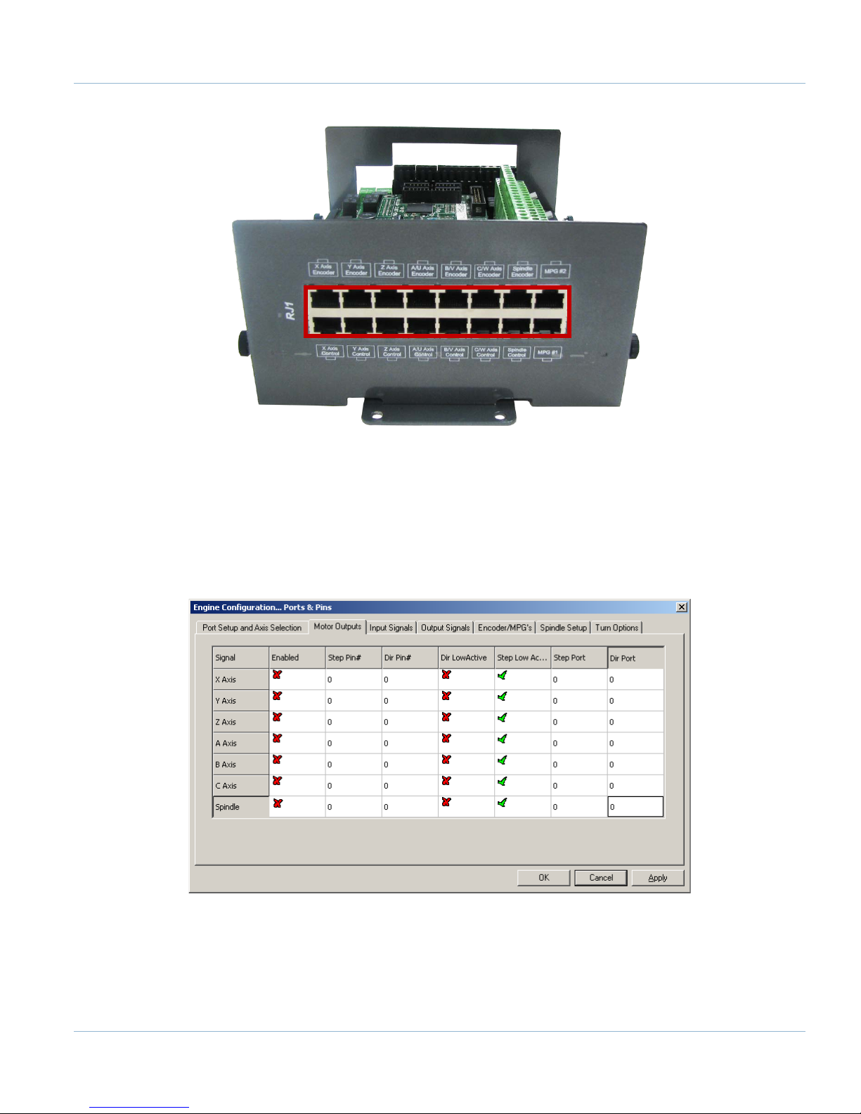
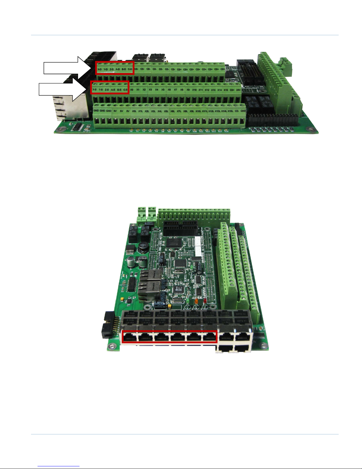
Next, plug the drive control and encoder cables into the Apollo III motion controller. The drive control connections
are located on the bottom row of the large RJ45 block. The encoder control connections are located on the top
row of the large RJ45 block. See the picture below.
FIGURE 8 APOLLO III COVER REMOVED
Apollo III Using Mach3
Page | 15
FIGURE 9 DIFFERENTIAL STEP AND DIRECTION, AND ENCODER FEEDBACK RJ45 CONNECTIONS
2.2 Enabling Axes
After the drives are connected to the Apollo III, open up Mach3, and enable the axes as follows:
Note: This may already be setup depending on your system.
1. On the menu bar, click Config->Ports and Pins.
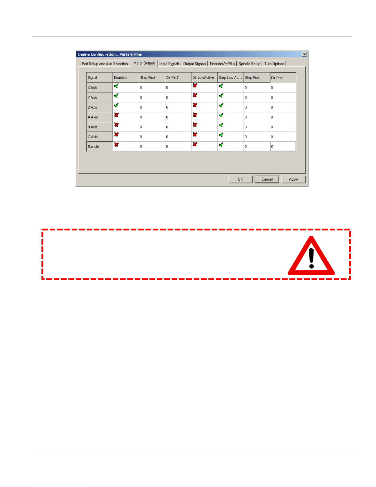
2. Select the Motor Outputs tab to see the axis enable options as pictured below.
FIGURE 10 AXIS SETUP
3. Enable all the axes that are to be controlled by setting the respective boxes in the Enabled column to
green checks. In the example below, the X, Y, and Z axes are enabled.
Apollo III Using Mach3
16 | Page
FIGURE 11 X, Y, AND Z AXES ENABLED
4. Press [OK] to save any changes and close the window.
The system is now set up for motion.
WARNING
The machine can be crashed very easily. No limit switches have been set up and the
units have not been configured yet.
2.3 Axis Calibration
For the machine to move the correct distance, the axes need to be calibrated. To get the units perfect, they must
be calculated manually from the machine specifications. However, you can get them extremely close if you use
the calibration wizard (see Calibration Wizard on page 18).
2.3.1 Manual Calibration
Complete the following procedure to do the manual calibration:
Note: If the MachMotion plugin is not listed under PlugIn Control, see the Axis Configuration Worksheet to do the
calculations by hand or use the calibration wizard on page 18. The worksheet can be found on the MachMotion
website under software setup documentation.
Go to PlugIn Control->MachMotion Plugin.
1. Select the Calibration tab.
2. Select the drive type of the axis being configured.
3. Enter the max motor RPM.
4. Enter the correct drive ratio.
Apollo III Using Mach3

Page | 17
Drive Ratio Apollo III
Drive Type
1
Teco
32
Mitsubishi
64
Yaskawa
1
Stepper
TABLE 2 – DEFAULT DRIVE RATIO VALUES
FIGURE 12 - MACHMOTION PLUGIN CALIBRATION CALCULATOR
5. Choose the machine configuration for the axis from the following three options.
a. Ball Screw
i. Enter the ball screw pitch
ii. Enter the gearing ratio between the shaft and the motor
Note: If the system has a pulley ratio and a gear box use this equation to get the total gear ratio:
[Gear Box Ratio] x [Pulley Ratio] = [Total Gear Ratio]
Ex: [10:1 Gear Box] x [30 Motor Pulley Teeth/15 Shaft Pulley Teeth] =
[10] x [30/15] = [20 Total Gear Ratio]
b. Rack and Pinion – Pinion Diameter
i. Enter pinion diameter
ii. Enter the gearing ratio between the shaft and the motor
c. Rack and Pinion – Rack Pitch
i. Enter number of teeth on pinion
ii. Enter the rack pitch
iii. Enter the gearing ratio between the shaft and the motor
6. Press the [Calculate] button.
7. Select the axis to calibrate.
8. Press the [Calibrate Axis] button.
Apollo III Using Mach3
18 | Page
9. Repeat starting at step 3 for each additional axis.
10. Restart Mach3 to save the calibration settings.
2.3.2 Calibration Wizard
Complete the following procedure to use the calibration wizard:
1. Run “M9990” from the MDI line.
2. Select the axis to calibrate.
3. Enter in the distance and federate the axis should move.
4. Measure how far the axis moved.
5. Enter in the distance the axis moved.
6. Allow it to update the Steps Per Unit for that axis if the measurement was correct.
7. Repeat this procedure until the axis is within the required accuracy.
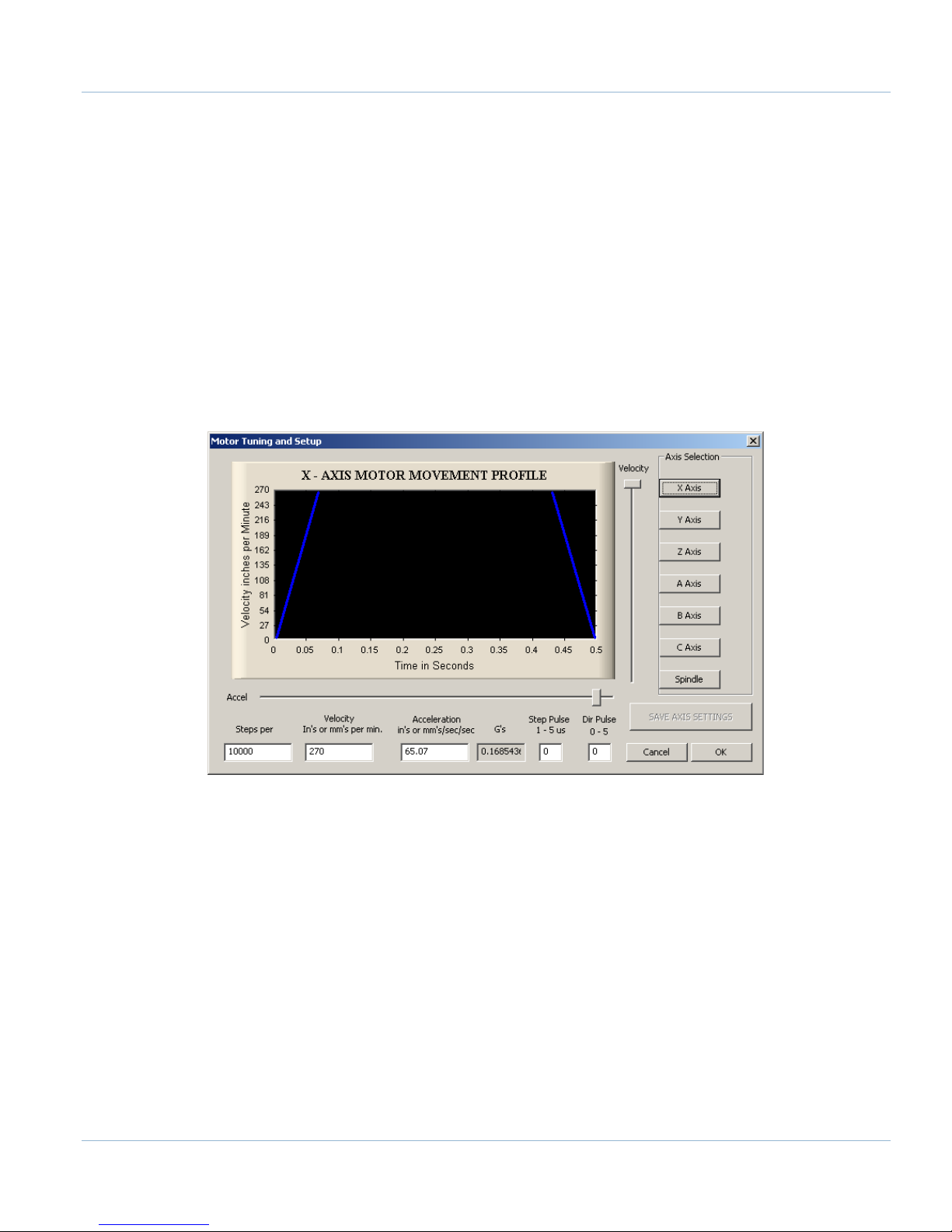
If you want to adjust your velocity, select Config on the top menu bar, then Motor Tuning. You should see the
Motor Tuning and Setup window as shown below.
In the column titled Axis Selection, press the button corresponding to the axis you want to set up. The selected
axis’s parameters will be loaded. Now you can adjust your velocity setting as shown below.
FIGURE 13 MOTOR TUNING AND SETUP
Apollo III Using Mach3

Page | 19
FIGURE 14 VELOCITY IN MOTOR TUNING
Press [SAVE AXIS SETTINGS] before clicking on another axis or closing out the Motor Tuning and Setup window.
WARNING
No limits have been set up. DEATH, INJURY or serious PROPERTY DAMAGE can occur if
the system is not operated carefully.
2.4 Backlash Calculation
The Apollo III has backlash compensation. Use the MDI line to enter G-Code to move the axes. To calculate the
machine’s backlash, follow the steps below.
1. Move an axis in one direction farther than the maximum possible backlash.
2. Mount a dial indicator and zero it.
3. Move the axis again in the same direction for a specific distance (it doesn’t matter how far).
4. Move the axis backwards the same distance.
5. Note how far the dial indicator was off from zero to see the axis’s backlash value.
6. On the menu bar go to Config->Config Plugins and press the [CONFIG] button on the HiCON plugin
line.
7. Select the tab corresponding to the desired axis.
8. Enter the backlash distance and speed as described below.
FIGURE 15 BACKLASH COMPENSATION
Apollo III Using Mach3

20 | Page
Backlash (mm, inch) – This field defines the backlash distance in inches or mm. The Apollo III uses this value to
calculate virtual load position.
Backlash Speed % – This field adjusts the maximum acceleration that the backlash counts can be applied. The
Apollo III takes the max acceleration from the motor tuning and multiplies it by this percentage. Valid values are
10-400 (0.1 to 4 times max acceleration). A common value is 20%.
WARNING
Do not leave the backlash speed zero if you enter in a backlash distance. The Apollo
III will not function.
2.5 Reversing Direction
If an axis moves the wrong direction, it can be reversed in the Mach3 software.
1. Navigate to the menu bar and click Config->Homing/Limits.
The following window will come up:
FIGURE 16 REVERSING DIRECTION
2. Under the Reversed column click on the red “X” if the axis needs to be reversed.
3. After making all the changes, press [OK].
The axis will now move the opposite direction than it did before.
2.6 Slaving an Axis
To configure an axis as a slave, follow the steps outlined below.
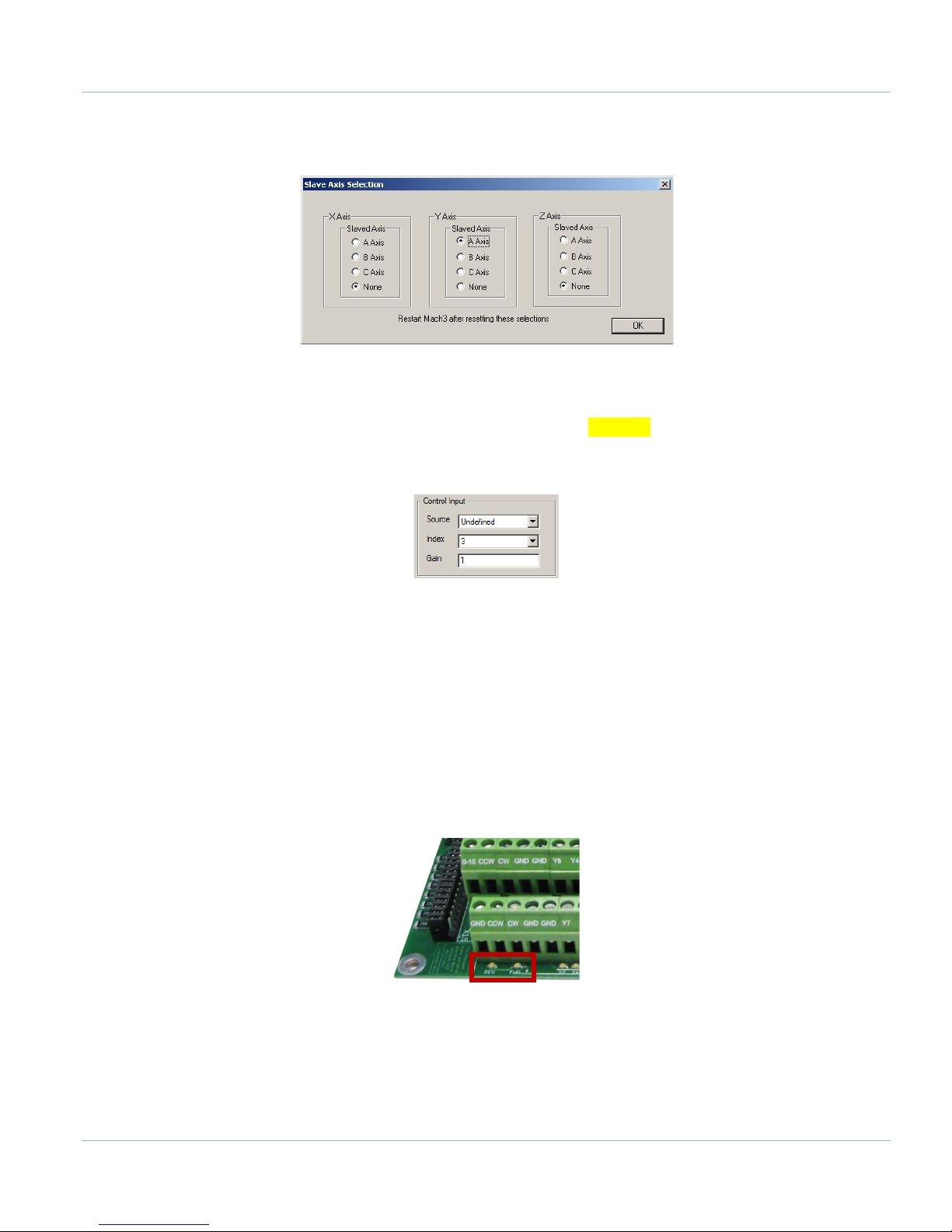
1. Click Config->Slave Axis on the main menu bar. It will display the Slave Axis Selection window.
Apollo III Using Mach3

FIGURE 17 SLAVE AXIS SELECTION WINDOW
2. Select the axis to be slaved. The X, Y, and Z aces can have A, B, or C as slaves. For example, the
configuration below is used to slave the A axis to the Y axis.
Page | 21
FIGURE 18 A AXIS SLAVED TO Y
3. Press [OK] and then restart Mach3.
3 SPINDLE SETUP
This section goes through the wiring and configuration process for spindle integration with Mach3. The Apollo III
spindle control consists of a 0-10V analog signal for spindle speed and two relays (CW and CCW) for spindle
direction. Below the spindle terminals there are two LEDs for spindle forward (FWD) and reverse (REV).
FIGURE 19 SPINDLE LEDS
3.1 Wiring a Spindle
3.1.1 VFD from MachMotion
The process for setting up a VFD from MachMotion is extremely simple. Simply plug the control cable into the
Spindle Control RJ45 jack located on the bottom row of the large RJ45 block.
Apollo III Using Mach3

22 | Page
FIGURE 20 SPINDLE CONTROL RJ45 JACK
3.1.2 VFD Other Than from MachMotion
Any VFD can be wired into the Spindle Control RJ45 jack by cutting the end off of a CAT5 cable and wiring the
loose ends to the VFD according the following pin out.
Function
Analog 0-
10VDC
CW
Relay
CW Relay
Drive
Enable
GND N/C
CCW
Relay
CCW
Relay
RJ45 Pins 1 2 3 4 5 6 7 8
Colors
White &
Orange
Orange
White &
Green
TABLE 3 SPINDLE CONTROL RJ45 JACK
Blue
White &
Blue
Green
White &
Brown
Brown
3.1.3 No VFD
If the system does not use a VFD to control the spindle, wire the spindle into the small green connecter as shown
below. Notice that 24V is wired to the CW and CCW relay contacts on the top row of the green connector.
Apollo III Using Mach3

Page | 23
0-10 CCW CW GND GND 24V Y2 Y0 C1+ 24V HEN 5EN 24V 5VY6 Y4 C2+
CW GND GND Y7 Y5 GND GND Y3 Y1 GND HEN 24EN SOV EXT GNDGND CCW
1 5
A1A2
2
3
4
C
O
M
N
O
N
C
Finder
97.01
11
14
12
COIL
Schneider
LC1D
Contactor
1/L1 3/L2 5/L3
13/NO 21/NC A1
2/T1 4/T2 6/T3
14/NO 22/NC A2
1 5
A1A2
2
3
4
C
O
M
N
O
N
C
Finder
97.01
11
14
12
COIL
Schneider
LC1D
Contactor
1/L1 3/L2 5/L3
13/NO 21/NC A1
2/T1 4/T2 6/T3
14/NO 22/NC A2
Spindle
Contactor Coil AC
Voltage Source
3 Phase
Source
Important!
Schneider Contactors are fitted
with Schneider LAD9R1V
Reversing Switch Kit
3.2 Spindle Configuration
3.2.1 Spindle Pulley Setup
For Mach3 to know how to scale the analog voltage output, the maximum RPM for the spindle motor must be
defined. If the machine has different gears Mach3 can have multiple maximum speeds. Mach3 uses a different
pulley for each different speed configuration.
For example, one pulley could be set to 75 to 300 RPM for a low speed (at 300 RPM the control will output
10V). A medium speed pulley could go from 300 to 1200 RPM and high speed pulley could run from 1200 to
2400 RMP.
To change the pulleys, go to Config->Spindle Pulleys. The Pulley Selection window will appear as shown in
Figure 22.
FIGURE 21 NO VFD SPINDLE WIRING
Apollo III Using Mach3

24 | Page
M-Code
Function
M3
Clockwise
M4
Counter/Clockwise
M5
Stop
FIGURE 22 PULLEY SPEED SETUP
Use the drop down menu titled Current Pulley to select the pulley to be updated. Enter in the maximum and
minimum speeds for each pulley. Then select the current pulley and press [OK].
Note: Only set up multiple pulleys if the machine has different gears.
Note: If the spindle is turning the wrong direction check the reversed box in the Spindle Pulleys window.
The pulleys can also be changed by using M41-M45. The macros can be used to just change pulleys in Mach3 or
they can be used to automatically change gears on the machine. Outputs 12-16 are configured to shift between
gears 1 and 5. To shift the machine into neutral, run M40. Open up the macros (M41-M45) with the VB Script
Editor for more details.
3.3 Turning on the Spindle
To control the spindle use the following M-Codes with an S word for spindle RPM in the MDI line (Ex. M3 S2000).
TABLE 4 SPINDLE M-CODES
If the spindle is not running correctly at this point some settings may need to change inside the VFD. In this
situation reference the VFD manufacturer manual.
Note: See the Mitsubishi VFD Installation Guide for setup information if it was purchased from MachMotion.
3.4 Reversing Direction
To reverse a pulley’s direction, go to Config->Spindle Pulleys. Select the pulley that needs to be reversed and
then check the small box called Reversed as shown below.
FIGURE 23 REVERSE PULLEY
Apollo III Using Mach3

Page | 25
A-D B-D C-D
C0- C0- C0- C0+ C0+ C0+
X-D Y-D Z-D
C0- C0+ C0+C0- C0- C0- C0+ C0+ C0+
X-S Y-S Z-S X0 X1 X2 X3 X4 X5 X6 X7 X8 X9 X10 X11 X12 X13 X14 X15 C0+ 24VA-S B-S C-S
GND GND GND 5V 5V 5V X0L X1L X0L X3L X4L X5L X6L X7L X8L X9L X10L X11L X12L X13L X14L X15L C0- GND
LS1 LS2 & Home Sw
Axis
Input Number
Axis
Input Number
X
X1 A X4 Y X2 B X5 Z X3 C X6
4 LIMITS AND HOMING SETUP
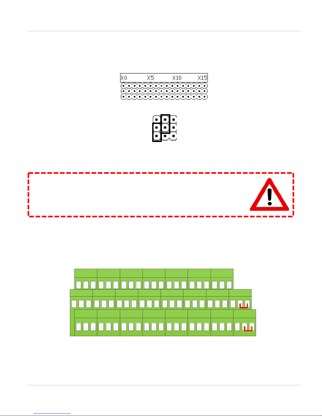
The Apollo III motion controller has up to 16 inputs that can be used for the limit and home switches. To maximize
the number of inputs available for other functions, wire multiple switches in series as shown below.
FIGURE 24 LIMIT SWITCHES IN SERIES
Note: For the highest level of safety, wire the limit switches Normally Closed.
The standard limit input allocation is show below.
TABLE 5 INPUT PORT AND PIN NUMBERS
To set up and wire 24V limit/home switches, follow the steps outlined below.
1. Pick two limit switches closest to the end of the axis’ maximum and minimum travel.
2. Wire the two switches normally closed in series as shown in Figure 24.
3. Wire the remaining side of the first switch to C0+ from the Apollo III motion controller.
4. Wire the remaining side of the limit/home switch into the correct input (see Table 5) depending on which
axis is being wired.
5. On the menu bar at the top of the screen select Config->Ports and Pins.
6. Click on the Input Signals tab (See Figure 25).
7. Enable the limit and home switches by clicking the red [X] by the signal to make it a green check.
Note: Each axis has three signals the max travel (X++), the min travel (X--), and the home (X Home). All
three must be enabled and set to the correct port and pin address for everything to work correctly using the
wiring description above.
8. Set the Port Number and Pin Number to the desired input. All input signals use port 11 and the pin
number corresponds to the X number it is wired to (Ex. An input wired into X3 will have a port number of
11 and a pin number of 3).
9. Set up the active low checkbox to a green check.
Note: Under the active low column the active state can be changed by clicking on the [X] or check mark. If
the limit switches are normally open the red X mark should be used. However, this is not recommended as it is
not as safe.
10. When the limit and home switches are completely configured, press [Apply] and then [OK].
Apollo III Using Mach3

26 | Page
FIGURE 25 INPUT SIGNALS
For example, the configuration above has X, Y, and Z limit and home switches enabled. All of them are wired
normally closed. The port and pin for X is port 11 pin 1 (X1) and for Y it is port 11 pin 2 (X2). Notice that all the
limit switches and the home switch for an axis have the same port and pin numbers.
4.1 Homing Setup
Now the limit and homing switches are set up correctly it is time to finish setting up homing.
1. Home each axis of the machine individually if possible. Note which axes home in the wrong direction.
Note: See the system operating manual for individual axis homing instructions.
WARNING
If the limit switches are not set up correctly or if an axis moves in the opposite
direction of the home switch, the machine could crash. Make sure to keep a hand on
the Emergency Stop button the first time the machine homes.
.........................................................................................................................................
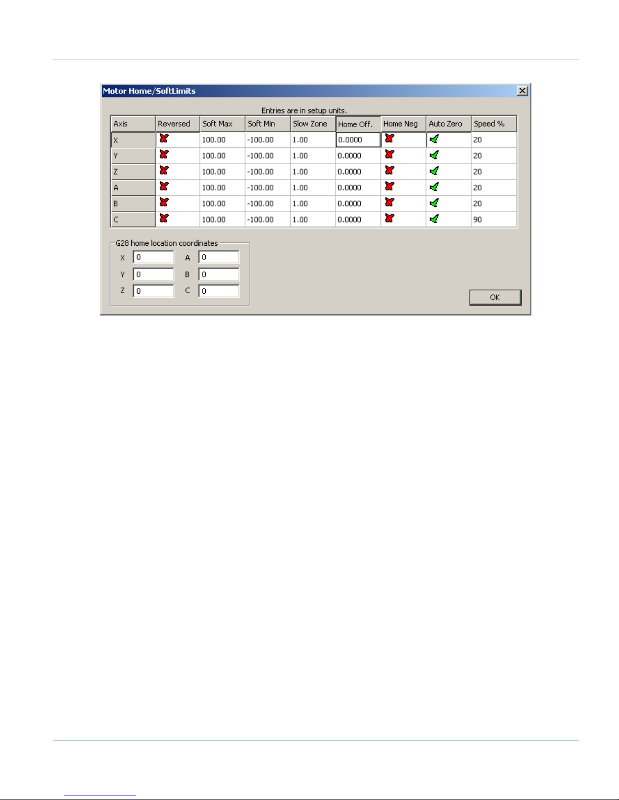
2. Open to the menu bar and click Config->Homing/Limits. The Motor Home/Soft Limits window will come
up as shown below.
Apollo III Using Mach3
Page | 27
FIGURE 26 MOTOR HOME/SOFT LIMITS
3. If any of the axes homed in the wrong direction, click on the red X next to the axis on the Home Neg
column.
4. Set the speed of the axis by changing the percentage under the Speed % column. Press [OK] to close the
Motor Home/Soft Limits window.
Homing on the machine should now be completely set up. Press the [Home All] button again to make sure that
everything works correctly.
4.2 Soft Limits Setup
Soft limits are utilized to keep the machine from crashing. If the soft limits are set up correctly, the machine will
never be able to hit a physical limit switch unless it is not homed properly. If at any time a command is made for
the machine to move outside of the soft limits (while they are enabled), an error will appear in the status line or a
window will pop up asking if the program should continue. To set up the soft limits, follow the procedure outlined
below.
1. Jog the machine to the maximum distance from the homing switches.
Note: Make sure to stay inside the physical limit switches. If the machine is jogged outside of the limit
switches, it completely defeats the purpose of soft limits.
2. Record the machine coordinates at the end of the travel.
3. Open the menu bar and click Config->Homing/Limits to bring up the Motor Home/Soft Limits window
will come up (See Figure 26).
4. For each axis enter in the recorded values.
Note: If the value is positive, place it into the Soft Max limit and set the Soft Min limit to zero. Otherwise,
with a negative value, set the Soft Max to zero and the Soft Min to the recorded value.
5. Press [OK].
Apollo III Using Mach3

28 | Page
Jumpers
Inputs
LEDs
FIGURE 27 SOFT LIMITS
6. Enable the soft limits (See the Operating Manual for more detail).
Note: Soft limits prevent the machine from being able to jog outside of the acceptable range. Also when
starting a G-Code file it will warn the operator if the file will go outside of the limits. However, if the
warning is ignored it will not prevent a G-Code file from overrunning them.
Test the soft limits by jogging the axes in all directions. As long as the machine is homed, it will never be able to
hit a hard limit switch.
5 INPUT SETUP
5.1 Generic Inputs
All 16 inputs on the Apollo III can be used for limit switches, home switches, tool changers, or anything else. To
learn how to set up limit switches, go to Setting up Limits and Homing on page 24. As shown below, the inputs are
located on the main green terminal block.
FIGURE 28 INPUTS
Note: Some of the input terminals and jumpers are not used for the Apollo I.
Apollo III Using Mach3
Page | 29
1 2 3
A-D B-D C-D
C0- C0- C0- C0+ C0+ C0+
X-D Y-D Z-D
C0- C0+ C0+C0- C0- C0- C0+ C0+ C0+
X-S Y-S Z-S X0 X1 X2 X3 X4 X5 X6 X7 X8 X9 X10 X11 X12 X13 X14 X15 C0+ 24VA-S B-S C-S
GND GND GND 5V 5V 5V
X0L X1L X0L
X3L X4L X5L
X6L X7L X8L
X9L X10L X11L X12L X13L X14L X15L C0- GND
Each input has an LED that shows the current state of the input. Both the LED and input are labeled with the input
name. The inputs run from X0, up to X15. If the LED is on, then the input is activated. Different configurations can
be selected for each input by using the jumpers near the bottom right of Apollo III. Each jumper corresponds to
an input. For example, the jumper labeled X10 corresponds to the input on TB1 labeled X10 and the LED X10.
FIGURE 29 INPUT JUMPERS
FIGURE 30 JUMPER POSITIONS
WARNING
Input X0 is configured as drive fault by default. If you have servo drives from
MachMotion, DO NOT connect anything to X0. It could damage your drives or Apollo III
motion controller.
5.2 Wiring Inputs
5.2.1 Standard 24V Inputs
For a standard 24V input, place the jumper on the bottom two pins. In the example below, all the inputs are set
up as standard 24V inputs. Next, connect C0+ to 24V and C0- to GND on TB1 as shown below.
FIGURE 31 24V CONFIGURATION
Apollo III Using Mach3

30 | Page
A-D B-D C-D
C0
- C
0
- C
0-
C0+ C0+ C0+
X-D Y-D Z-D
C0
- C0+ C0+
C0
- C
0
- C
0-
C0+ C0+ C0+
X-S Y-S Z-S X0
X1 X2X
3 X
4
X5
X
6 X
7
X8
X
9 X
10
X11
X
12 X13 X14
X15 C0+ 24VA-S B-S C-S
GND GND GND 5
V
5V
5
V
X
0L
X
1L
X
0L
X
3L
X
4L
X
5L
X
6L
X7L X8L
X9L X10L X11L X12L X13L X14L X15L C0- GND
Switch
Jumper
position
1
A-D B-D C-D
C0
- C0- C0-
C0
+ C0
+ C0+
X-D
Y-D
Z-D
C0- C
0+
C0+
C0- C0- C0- C0
+ C0
+ C0+
X
-S Y-
S Z
-S
X0 X1
X2
X3 X4 X5 X6 X7
X8 X9 X
10 X11
X12 X13
X14
X15 C0+ 24VA-S B
-S C
-S
GND
GND GND5V 5V
5V
X
0L X1L X0L
X3L X4L X5L X6L X7L
X8
L
X
9L X
10L X
11L
X
12L X
13L X14L
X15L C0- GND
Jumper
position
2
Then connect the input to the input terminal on the middle row (X1, X2, etc.). See the diagram below.
FIGURE 32 STANDARD 24V INPUT
To activate the input, 24V must be supplied to the input. A floating signal or a ground will not turn on the input.
The LED corresponding to the input will turn on brightly when the input is activated.
5.2.2 Sinking Inputs (NPN)
For most NPN proxys place the jumper on the top two pins. Then connect the signal into the corresponding input.
See the example below.
If the proxy has an internal pull-up resistor, depending on its size, it could require the jumper to be completely
removed. Use a 3.9k ohm resistor and connect it between XSL and C0+.
Below is an example of a 24V NPN proxy with an internal pull-up resistor. The jumper on the Apollo III must be
completely removed for this to work.
FIGURE 33 STANDARD NPN PROXY
Apollo III Using Mach3

Page | 31
A-D B-D C-D
C0- C0- C0-
C0+ C0+ C0+
X-D Y-D Z-D
C0- C0+ C0+
C0- C0- C0-
C0+ C0+ C0+
X-S Y-S Z-S
X0 X1 X2 X3 X4 X5
X6 X7 X8 X9 X10 X11 X12 X13 X14 X15 C0+ 24VA-S B-S C-S
GND GND GND 5V 5V 5V
X0L X1L X0L X3L X4L X5L X6L X7L X8L
X9L X10L X11L X12L X13L X14L X15L C0- GND
NPN Proxy
3.9k
Ohm
Jumper
position
3
A-D B-D C-D
C0- C0- C0- C0+ C0+ C0+
X-D Y-D Z-D
C0- C0+ C0+C0- C0- C0-
C0+ C0+ C0+
X-S Y-S Z-S X0 X1 X2 X3 X4 X5 X6 X7 X8 X9 X10 X11 X12 X13 X14 X15 C0+ 24VA-S B-S C-S
GND GND GND 5V 5V 5V X0L X1L X0L X3L X4L X5L X6L X7L X8L X9L X10L X11L X12L X13L X14L X15L C0- GND
PNP Proxy
Jumper
position
1
FIGURE 34 NPN PROXY WITH INTERNAL PULLUP
5.2.3 Sourcing Inputs (PNP)
For PNP proxies place the jumper on the bottom two pins. Then connect the signal into the corresponding input.
See the example below.
Figure 35 24V Proxy Example
5.3 Configuring Inputs
To configure an input, follow the procedure below.
1. On the menu bar click on Config->Ports and Pins.
2. Select the Input Signals tab. Scroll down to the desired input. There are 4 inputs and 15 OEM triggers.
An OEM trigger acts exactly like an input.
Apollo III Using Mach3

32 | Page
FIGURE 36 INPUT CONFIGURATION
Note: The note below the input signal window is referencing parallel port systems. Ignore this.
3. Enable the input by clicking on the red “X”. If it is a green check mark, it is already enabled.
4. Set the Port Number and Pin Number to the desired input.
Note: All input port numbers are 11 and the pin numbers correspond to the X number
(X4 would be pin 4)
5. To change when the input is active, click on the Active Low column. A green check mark means that the
input is active low and a red X means that the input is active high.
The input is now be set up.
6 OUTPUT SETUP
6.1 Generic Outputs
The Apollo III has 8 logic outputs that can be used for any low current application. They are located on the small
green terminal block as shown below.
Apollo III Using Mach3

Page | 33
0-10 CCW CW GND GND 24V Y2 Y0 C1+ 24V HEN 5EN 24V 5VY6 Y4 C2+
CW GND GND Y7 Y5 GND GND Y3 Y1 GND HEN 24EN SOV EXT GNDGND CCW
+ 24V Load -
FIGURE 37 OUTPUTS
Each output has an LED that shows its current state. The outputs and LEDs are labeled Y0 through Y7. If the LED is
on, the output is activated.
6.2 Wiring Outputs
There are two separate commons for the outputs. The common C1+ is for outputs Y0-Y3 and C2+ is for Y4-Y7.
Each common can take 7-48VDC. If the outputs being used are using the voltage supply from Apollo III, each
output can only supply 125mA. However, if they are supplied using a separate voltage source, each output can
source up to 250mA.
For standard operation the outputs can have their commons jumpered to 24V on the Apollo III. At that point
simply connect the load between the output and GND. See the figure below.
FIGURE 38 STANDARD 24V 125MA OUTPUTS
Apollo III Using Mach3

34 | Page
6.3 Configuring Outputs
To configure an output, follow the procedure below.
1. On the menu bar click on Config->Ports and Pins.
2. Select the Output Signals tab.
3. Scroll down to the desired output (There are 20 outputs that can be used).
FIGURE 39 OUTPUT CONFIGURATION
Note: The note below the output signal window is referencing parallel port systems. Ignore this.
4. Enable the output by setting the Enabled box to a green check.
5. Set the Port Number to 11 and the Pin Number to the corresponding Y number (Y3 would be pin number
3).
6. Set the Active Low column to a green check for a normally closed signal or red x for normally open.
6.4 Using Outputs
Outputs 5-10 can be controlled with M-Codes. One M-Code turns an output on, and the other M-Code turns the
output off. Use the table below for a reference.
Apollo III Using Mach3

Custom M-Codes
Functions
Default Output
M200
Output 5 on
M201
Output 5 off
M202
Output 6 on
M203
Output 6 off
M204
Output 7 on
M205
Output 7 off
M206
Output 8 on
M207
Output 8 off
M208
Output 9 on
M209
Output 9 off
M210
Output 10 on
M211
Output 10 off
Feature
ON M-Code
OFF M-Code
Preconfigured Output
Mist
M7
Output 3 - Y0
Flood
M8
Output 4 - Y1
Y2
Y3
Y4
Y5
Y6
Y7
TABLE 6 M-CODES FOR OUTPUTS
The outputs can also be accessed inside the MachMotion plugin. Read Mist and Flood Control
Advanced Options on page 35 for more information on how to use outputs inside the plugin.
6.5 Mist and Flood Control
Page | 35
Mist is already preconfigured in Mach3 to be wired into Y0 on the small green connector.
M9
TABLE 7 MIST AND FLOOD CONTROL
7 ADVANCED OPTIONS
A number of advanced features can be accessed and configured in the MachMotion plugin such as periodic oiler
control and custom user messages. Begin by going to PlugIn Control->MachMotion Config to open the
MachMotion plugin.
Apollo III Using Mach3

36 | Page
I/O
Output
FIGURE 40 - MACHMOTION PLUGIN, IO CONFIGURATION
In general, only change values and settings in the red boxes shown above. The rest of the options are used to set
up the control at the factory. Please do not change these settings.
The I/O Configuration section allows an input to turn on a function. The input in the drop down menu turns on the
corresponding function. In the figure above, OEM trigger 1 (OEMTRIGGER1) turns on the drive fault.
For example, to set up an external E-Stop, configure a normal input in ports and pins (See Setting up Inputs).
Let’s assume we set up Input 4. Then use the drop down menu in the System Configuration window to select the
input as shown below.
The system may also require an oiler. Just define an output, set the time run time of the oiler, and the time
between cycles. In the example below the oiler is attached to output 6. It is turned on for 10 seconds every 1
minute. The spindle has to be on for the oiler to turn on.
FIGURE 41 OILER
Apollo III Using Mach3

User
FIGURE 42 CYCLE START
Now whenever Input4 is active, E-Stop will be flagged.
Page | 37
The User Messages can be configured to have custom messages displayed. Each input will do a specific function
(E-Stop, feed hold, stop) and write to the status bar except the No Action option. The No Action just displays the
message on the status bar whenever the input is active. In the example below, when OEM trigger 4 is activated,
the message “MCR Reset!” will be displayed on the status bar.
FIGURE 43 - MACHMOTION PLUGIN, USER DEFINED MESSAGES
FIGURE 44 USER MESSAGES
Apollo III Using Mach3

38 | Page
**This page intentionally left blank**
Apollo III Using Mach3

Part 2:
Page | 39
ADVANDED SETUP
Apollo III Using Mach3

40 | Page
Location
IP Address
Apollo III
192.168.0.35
Computer
192.168.0.10
Control
Control
Apollo III
Ethernet Ports
8 PART 2: ADVANCED SETUP
8.1 Apollo III Network Connection
The Apollo III can be connected directly to the control or via an Ethernet router. Either of the two Ethernet ports
on the Apollo III can be used. The Ethernet ports have a built in Ethernet switch so you can also use them to daisy
chain other Ethernet devices together on a local network.
FIGURE 45 ETHERNET CONNECTOR
8.1.1 Direct Connection
To set up the Apollo III to communicate with the control directly, the network configuration needs to be assigned a
static IP address. The default static IP configuration is defined below.
TABLE 8 STATIC IP ADDRESSES
FIGURE 46 DIRECT NETWORK CONFIGURATION
Apollo III Using Mach3

8.1.1.1 CONFIGURING A STATIC IP ADDRESS ON WINDOWS 7
1. Click on the network icon on the system tray.
FIGURE 47 SYSTEM TRAY
2. Click on Open Network and Sharing Center.
3. In the top left corner of the Network and Sharing Center window click on Change adapter settings.
4. Right click on the network port that the Apollo III is connected to and select Properties.
5. From the list below double click on Internet Protocol Version 4.
Page | 41
FIGURE 48 LOCAL AREA CONNECTION PROPERTIES
6. Fill out the options as seen below.
FIGURE 49 IPV4 PROPERTIES
7. Press [OK] and close out the rest of the windows.
The control now has the correct static IP address.
Apollo III Using Mach3

42 | Page
Control
Control
Internet
Internet
Apollo III
Router
Router
File Type
File Name
Location
Plugin
M3HiCON.dll
C:\Mach3\PlugIns
Firmware
HiCONfw-X.XX.bin
C:\Mach3\MotionControllers\Apollo III
8.1.2 Router Connection
When using a network router to connect the Apollo III to the control there is no special network setup required.
The router will take care of the IP assignments.
FIGURE 50 NETWORK CONNECTION THROUGH A ROUTER
8.2 Apollo III Software Installation
8.2.1 Installing Apollo III Plugin and Firmware
The plugin and firmware manage the communication and operation of the Apollo III.
Once the files are downloaded on the control, put them in the locations specified below.
TABLE 9 APOLLO III FILES AND LOCATIONS
Note: If the file location for the firmware does not exist, create the folders.
8.2.2 Installing VSI Manager
The VSI manager interfaces with the Apollo III motion controller for updating firmware and managing the
connection. To install the manager go to the Downloads page at MachMotion.com. Run the installation program
using the default options.
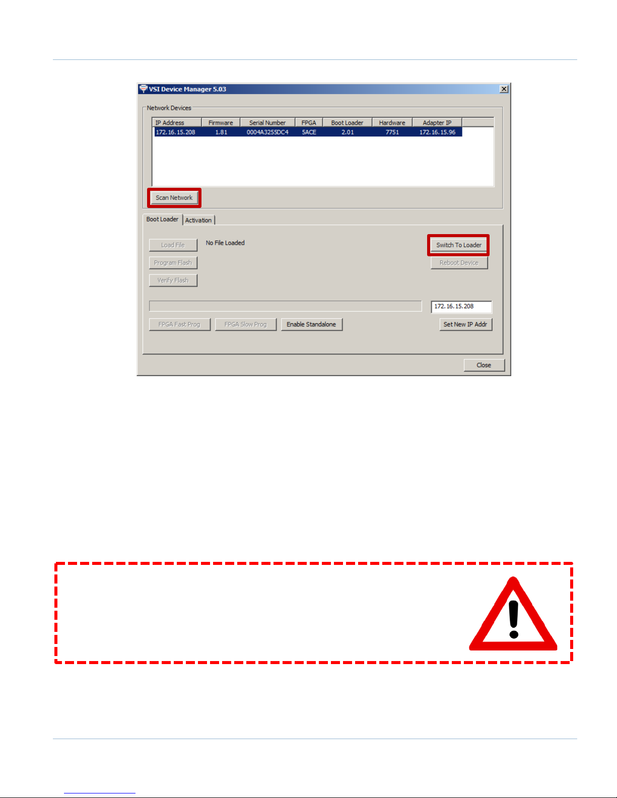
To download the firmware to the Apollo III, follow the procedure below:
1. Open the VSI Device Manager program.
2. Click on the [Scan Network] button.
Apollo III Using Mach3
Page | 43
FIGURE 51 VSI DEVICE MANAGER
Note: A device should show up as shown.
3. Select the device and press [Switch To Loader].
4. Click through the message windows that pop up and click on [Load File].
5. Select the .bin file from the location specified in Error! Reference source not found..
6. Press [Program Flash] and wait until it finishes programming.
7. Press [OK] when it asks to reboot to launch the new firmware.
8. Close the device manager.
The firmware should now be updated.
WARNING
Install the plugin AND download the firmware to the Apollo III. If the firmware
and plugin versions do not match, it could cause serious damage to the
machine or cause the Apollo III not to operate at all.
Apollo III Using Mach3

44 | Page
8.3 Mach3 Integration
8.3.1 Mach3 Startup
Open up the Mach3 software, making sure to select the correct profile. Select the M3HiCON plugin as shown
below. Make sure to select Don’t ask me this again.
FIGURE 52 DEVICE PLUGIN SELECTION WINDOW
After Mach3 has completely loaded, the status bar at the bottom of the screen should say “HiCON Online.
Plugin: X.XX, Board: XXXX / X.XX, FPGA: XXXX” where the Xs represent the version numbers. If this message
comes up, then everything is connected correctly.
If the status bar in Mach3 says “HiCON Board Not Found,” then check the Ethernet cable’s connection and the
control’s IP configuration. If Mach3 continually pops up with errors, make sure that the correct firmware (that
matches the current plugin) is downloaded in the Apollo III.
8.4 Apollo III Status Window
To view the status of the Apollo III from inside Mach3, click on PlugIn Control on the top menu bar and then
select HiCON Status.
The HiCON Status window shows the current state of the encoders, the inputs, and the outputs.
Apollo III Using Mach3

Page | 45
FIGURE 53 HICON STATUS WINDOW
The outputs can be toggled by clicking on the output LEDs. If an output is defined inside Mach3 under Ports and
Pins, then clicking on the output LED will have no effect. This window can be left open while running Mach3.
The P stands for the port number. So output Y0 is port 11 pin 0 located at P11 column 0.
Note: The HiCON Status window is a great place to check for encoder feedback.
8.5 Apollo III Configuration
To change anything inside the controller, the HiCON plugin must be used. Click Config on the main menu bar,
then Config PlugIns. Select the yellow CONFIG button next to the M3HiCON-www.VSI99.com-HICON-X.XX
plugin as shown below.
Apollo III Using Mach3

46 | Page
FIGURE 54 HICON PLUGIN
Once the HiCON plugin config is launched, a window with the following seven tabs will appear:
1. System
2. Axis X(0)
3. Axis Y(1)
4. Axis Z(2)
5. Axis A(3)
6. Axis B(4)
7. Axis C(5)
Each axis tab besides the System tab represents an axis to be controlled through the Apollo III. By default, the
System tab will be selected as shown below.
Apollo III Using Mach3

Page | 47
FIGURE 55 HICON CONFIGURATION WINDOW
At any time while inside the plugin, clicking on the [UPDATE HICON] button will transmit the settings to the Apollo
III motion controller. Clicking [OK] will also transmit the settings to the controller and save them in the selected
Mach3 profile (e.g. Mach3Mill, Mach3Turn, etc).
To exit the plugin, press [OK] and then [OK] again on the PlugIn Control and Activation window.
Now, with a brief overview of the Apollo III, it is time to start configuring the controller.
Apollo III Using Mach3
48 | Page
Signal / LED
Mach3 Name
Port #
Pin #
Active
Input / Output
Enable
Enable (1 through 6)
14 0 High (Red X)
Output
Drive Enable
Enable (1 through 6)
14 1 High (Red X)
Output
E-Stop
E-Stop
14
5
Low (Green Check)
Input
E-Stop LED
E-Stop Terminals
9 ENABLE CIRCUIT
The Apollo III has a hardware enable and a drive enable circuit. However, before they will work, the emergency
stop circuit must be set up. Use the table below as a quick reference for the different signals.
TABLE 10 ENABLE CIRCUITS
WARNING
Do NOT connect 115VAC to any part of the Apollo III motion controller. It could
cause serious damage to the controller.
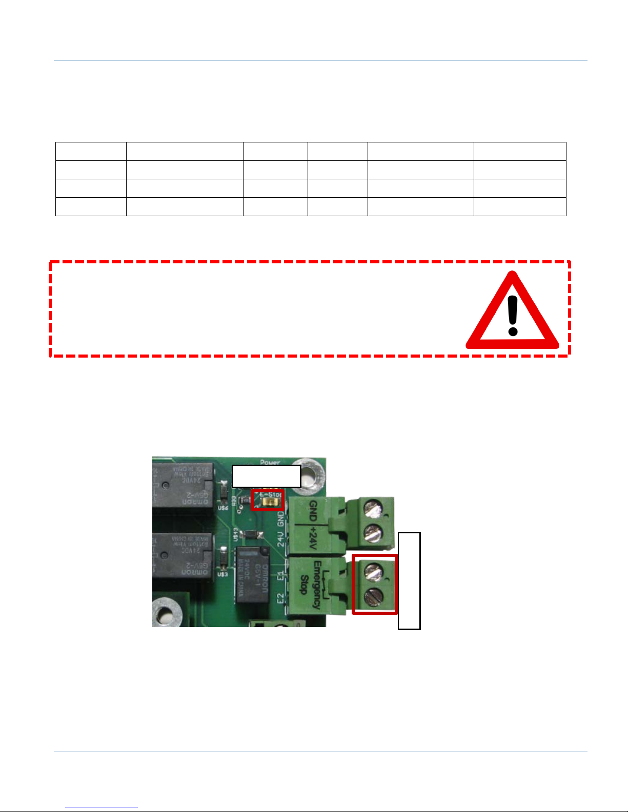
9.1 Emergency Stop
The emergency stop connector is located right below the power connector on the Apollo III. When the emergency
stop terminals are connected together, the red E-Stop LED turns on and the controller can then enable.
Note: Nothing will work on the Apollo III motion controller unless the Emergency Stop terminals are connected
Emergency stop input is set up inside Mach3 by setting the E-Stop signal to port 14 pin 5. When it is set up
correctly, any time the emergency stop terminals are disconnected, Mach3 will be reset.
FIGURE 56 EMERGENCY STOP CONNECTION
together!
Apollo III Using Mach3

Page | 49
FIGURE 57 MACH3 E-STOP SETUP
9.2 Hardware Enable
The hardware enable is the main enable circuit. It enables all the components on the Apollo III, turns on the 5V
enable (5EN) and the 24V enable signals (24EN), and activates the hardware enable relay (HEN). When the
hardware enable is set up correctly, it will only activate when there are no emergency conditions. Tripping the
emergency circuit or a limit switch will disable the hardware enable. Remember that the emergency stop
terminals must be connected for anything to enable.
The 5V and 24V enable signals can be used for any low current applications. The hardware enable relay can
be used for higher current applications up to 48V if an external voltage source is provided. The signals are
labeled 5EN, 24EN, and HEN on the Apollo III terminal block TB2 as shown below.
Apollo III Using Mach3

50 | Page
0-10 CCW CW GND GND 24V Y2 Y0 C1+ 24V HEN 5EN 24V 5VY6 Y4 C2+
CW GND GND Y7 Y5 GND GND Y3 Y1 GND HEN
24EN
SOV EXT GNDGND CCW
+ 48V Supply -
48V Load
FIGURE 58 HARDWARE ENABLE SIGNALS
View the diagram below for an example of the hardware enable relay wiring.
FIGURE 59 HARDWARE ENABLE RELAY EXAMPLE
The green LED (labeled Enable) turns on as soon as the controller detects the enable signal from Mach3. The LED
does not mean that the hardware enable circuit is activated. The hardware enable circuit is only activated when
the red (E-Stop), orange (Power), and green (Enable) LEDs are on.
Apollo III Using Mach3

Page | 51
Enable
FIGURE 60 HARDWARE ENABLE LED
Hardware enable is set up inside Mach3 by setting one of the Enables to port 14 pin 0. Each enable signal
corresponds to an axis (Enable1 = X, Enable2 = Y, etc). Make sure that the axis corresponding to the enable
signal used is enabled under the Motor Outputs tab. For example, a lathe with only the X and Z axes enabled
should not use the Enable2 (Y axis enable) signal.
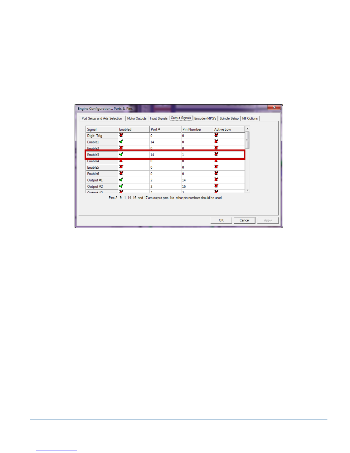
9.3 Drive Enable
Drive enable is used to enable all the drives. When activated the drive enable relay connects the external
enable (EXT) to the servo enable (SOV) terminals on TB2. The signal SOV runs to each axis control RJ45 jack.
EXT can be jumpered to 5V, 24V, GND, or any other DC voltage up to 48V for different enable signals
depending on what the servo drives require. Again, remember that the emergency stop terminals must be
connected for anything to enable.
FIGURE 61 MACH3 HARDWARE ENABLE SETUP
Apollo III Using Mach3

52 | Page
0-10 CCW
CW GND GND
24V
Y2
Y0
C1+
24V HEN
5EN 24V 5VY6 Y4 C2
+
CW GND GND Y7 Y5
GND
GND Y
3 Y1
GND HEN
24EN
SOV EXT GNDGND CCW
Drive Enable
FIGURE 62 DRIVE ENABLE SIGNALS
The Mitsubishi, Yaskawa, and TECO servo drives from MachMotion are all enabled with a ground signal.
Therefore EXT and GND are connected together as shown below.
FIGURE 63 DRIVE ENABLE EXAMPLE
The blue LED (labeled Drive Enable) on the top middle of the controller turns on as soon as the drive enable
signal from Mach3 is detected. The blue LED does not mean that the drive enable relay is activated. The drive
enable relay is only activated when the red (E-Stop), green (Enable), and blue (Drive Enable) LEDs are on.
FIGURE 64 DRIVE ENABLE LED
Apollo III Using Mach3
Page | 53
If the system needs to use the drive enable signal without using the axis control cables, just connect the signal
directly to SOV.
Drive enable is set up inside Mach3 by setting one of the Enables to port 14 pin 1. Each enable signal
corresponds to an axis (Enable1 = X, Enable2 = Y, etc). Make sure that the axis corresponding to the enable
signal used is enabled under the Motor Outputs tab. For example, a lathe with only the X and Z axes enabled
should not use the Enable2 (Y axis enable) signal.
FIGURE 65 MACH3 DRIVE ENABLE SETUP
Now with the enable circuits set up, the next step is to set up the machine axes.
10 AXES
To set up the axes, the drives must be connected to the controller, the Apollo III controller must be configured,
and the Mach3 software must be set up as defined below.
10.1 Connecting Drives
The Apollo III motion controller uses step and direction to control the axes. It can use differential or single-ended
outputs. For differential outputs there are two signals for step (step + and step -) and two signals for direction
(direction + and direction -). For single-ended there is only one signal for both step and direction. All
MachMotion products use differential outputs.
10.1.1 Differential Control
Most systems use differential step and direction. The step and direction outputs are located on the bottom row of
RJ1, the large RJ45 jack block. See the diagram below.
Apollo III Using Mach3

54 | Page
Drive
Error
Direcon
+
Drive
Enable
Direcon
-
RJ45 Pins
X Axis
Y Z A B C
FIGURE 66 DIFFERENTIAL STEP AND DIRECTION RJ45 JACKS
The pinout for the RJ45 jacks is shown below.
Funcon Reserved
1 2 3 4 5 6 7 8
Colors
Any drive from MachMotion can be plugged directly into the axis control RJ45 jacks.
10.1.2 Single-Ended Control
To use single-ended control use the terminals on TB1 (the large green terminal block). The top row is for the
direction signals and the middle row is for the step signals. The first letter on each terminal is the axis name and
the second letter is the function (D for direction and S for step). See the picture below.
White &
Orange
Orange
White &
Green
TABLE 11 AXIS CONTROL RJ45 JACK PINOUTS
Blue
GND
White
& Blue
Green
Step + Step -
White &
Brown
Brown
Apollo III Using Mach3
Page | 55
Direction
Step
Y
Z
Axis A Axis
B
Axis
C
Axis
X
TABLE 9 SINGLED-ENDED STEP AND DIRECTION TERMINALS
With the drives connected it is time to connect the encoder feedback. Skip the next section if the system does not
have encoder feedback or if it is not going to be set up at this time.
10.1.3 Encoder Feedback
The encoder feedback inputs are located on the top of RJ1. The encoder signal for each axis is directly above
the control signal. See the diagram below.
Axis
Axis
FIGURE 67 ENCODER FEEDBACK RJ45 JACKS
Apollo III Using Mach3

56 | Page
Funcon
A+
A-
B+
5V
GND
B-
I+
I-
RJ45 Pins
The Apollo III uses a 5V encoder signal. See the pinout below.
1 2 3 4 5 6 7 8
Colors
Again any drives purchased from MachMotion can have their encoder feedback plugged directly into the
encoder RJ45 jacks.
White &
Orange
Orange
TABLE 12 ENCODER FEEDBACK RJ45 JACK PINOUT
White &
Green
Blue
White &
Blue
Green
White &
Brown
10.2 Configuring Axes
The axes must also be configured inside the HiCON plugin. Begin by opening up the plugin. Select the tab
corresponding to the axis to be configured.
Brown
The control parameters are used to configure the axes. If the Apollo III came with a MachMotion control all of the
following parameters will already be set up. For all other systems, the only parameter that should have to
change is the Feedback. If the system has encoder feedback, make sure to select the correct encoder under the
Feedback drop down bar. The encoder index starts at 0. So for the X axis use Encoder0, for the Y axis
Encoder1.
FIGURE 68 X AXIS CONFIGURATION
Apollo III Using Mach3

Parameter Name
Value
Source
MACHxx
Index
N*
Gain
1
Output
StepGenN*
Feedback
EncoderN*
Max Follow Error
10000
The default parameters are shown below:
TABLE 13 CONTROL PARAMETERS
*N is the axis number with 0 being X, 1 being Y, 2 being Z, etc.
To update the control parameters, press the UPDATE HICON button. Clicking on OK or the SAVE
CONFIGURATION buttons saves the entire configuration to the selected Mach3 profile.
Page | 57
The axes should now be set up enough to jog the machine.
WARNING
The machine has not been calibrated so it could jog at extremely high speeds and
move erroneous distances. Also, no limits have been set up so DEATH, INJURY or
serious PROPERTY DAMAGE could result if extreme caution is not used.
If more information is desired about the control parameters, please read the section below.
10.2.1 Control Parameters
Source – Source defines the input type for the controller for a particular axis. This should be set to MACHxx. If the axis is not
used, it must be disabled by selecting Undefined.
Index – Index defines the index of the controller source. This is equal to the axis number (X = 0, Y = 1, Z = 2, etc).
Gain – The control input (commanded) is multiplied by this number. Leave this at 1 for most applications.
Output – Output defines the output for the controller for a particular axis. The possible values are:
StepGenX: This setting uses step and direction as the output. X refers to the axis number.
Undefined: This setting is used to disable the axis and to ignore the control output index. If the axis is not enabled, then the
Output must be set to Undefined.
Feedback – Feedback defines the feedback type for the controller for the selected axis. The possible values are:
Encoder: Use one of the differential hardware encoder inputs 0…7 as the feedback.
None: Use this if the system is not going to use encoder feedback.
Homing Type – Defines the homing sequence for each axis. Two types of homing sequences are supported:
Apollo III Using Mach3

58 | Page
Home Sensor: (Homing with or without an Index Pulse)
The axis moves in the configured direction until a home sensor is seen. It then moves in the opposite direction at 20% of initial
speed until the sensor is not seen. If Use Index Pulse is checked, then the axis will continue moving until it finds the index pulse.
At this point the home position is defined.
IndexPulseOnly: (Use only the Index pulse to Home)
The axis moves in the configured direction to locate the index pulse to home the axis. As soon as the index pulse is detected, it
clears the position counter to indicate the home position and stops the axis.
Max Follow Error – Defines the number of steps between the commanded position and the actual position (from the encoder
feedback) before an emergency condition is triggered. This value is only applicable if the system is using encoder feedback.
10.3 Testing Motion
The test motion module is only useful if encoder feedback is being used. For most applications this will never be
needed. However, this can be used to optimize the system acceleration and velocity. It allows the following error
of the machine to be viewed during commanded movements. Utilize the figure below as a reference.
FIGURE 69 TEST MOTION
Follow the steps below to test motion.
1. Enter in the desired axis velocity in units per minute
2. Enter in the desired acceleration value for the machine
3. Select the Relative or Absolute option
Note: Relative moves the machine X distance from its current position. Absolute moves the machine to the machine
coordinate position (distance from home). Relative is generally recommended.
4. Enter the distance in the Position user input.
5. Press the button DRIVE ON to turn on the LED beneath the button. This enables the drives. When the LED is
green, the drives are enabled.
Note: To download a new configuration to the Apollo III, DRIVE ON must be disabled.
6. Press EXECUTE to command the movement
The axis can also be homed by pressing the HOME button. Make sure that homing is set up in Mach3 before
using this function.
Apollo III Using Mach3
Page | 59
By selecting the AutoReverse check box, the system can make the axis reverse direction automatically for the
next motion command and thus avoid the axis continuing on in one direction during testing. The Ready LED shows
if the Apollo III is ready to accept a motion command. If the Ready LED is green, it implies that the controller is
ready to accept new motion commands. While executing a motion profile, the Ready LED turns to red and
Apollo III cannot accept a new motion command until the current motion sequence is completed or cancelled.
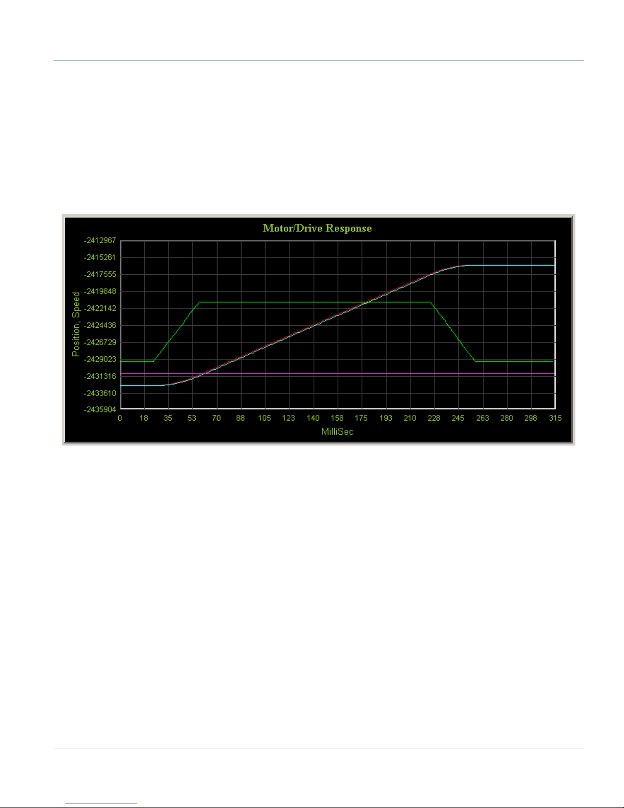
Once the test motion command has completed, the accuracy of the commanded motion profile can be seen on the
on the Motor/Drive Response graph. The acceleration and velocity can be optimized to get the machine’s
following error to a minimum.
FIGURE 70 MOTOR/DRIVE RESPONSE GRAPH
The blue line represents the actual position, the red line shows the commanded position, and the green line
displays the actual speed. Therefore the distance between the blue line and the red line is the following error.
Below is a review of all the test motion parameters. Read this section for more information.
10.3.1 Test Motion Parameters
Position – Test motion final position or displacement in terms of Position Units, e.g. 1.5, 10.093, mm or inches etc.
Acceleration – Test motion acceleration value in terms of Units per second
Velocity – Test motion velocity value in terms of Units per minute, e.g. inches/minute, mm/minute etc.
Relative and Absolute – These check boxes indicate whether the value in the Position field is the distance to travel (relative) or the
final position (absolute).
Execute Button – Transmits Execute Motion command to Apollo III. In addition, it also downloads control parameters before
starting the motion. User can press the CANCEL button to cancel the motion execution anytime during the machine operation.
Make sure that the axis control settings have been downloaded by clicking UPDATE HICON before clicking on EXECUTE. Motion
commands can be run by pressing the EXECUTE button when the Ready LED is green.
DRIVE ON Button – By clicking this button, the plugin downloads the parameters and enables the drives. If DRIVE ON is active, the
LED below this button will turn to green. Otherwise it will be red.
squared, e.g. inches/second2, mm/sec2 etc.
Apollo III Using Mach3

60 | Page
HOME Button – Executes the homing sequence based on selected homing settings.
Reverse - Checking this option will multiply the parameter in the position box with -1 and thus the direction of motion will be
reversed.
Auto Reverse - Checking the auto reverse option will toggle the “reverse” option between two consecutive motion commands, thus
the user does not have to manually reverse the direction of the motion every time.
Axis Position Display (DRO) – Shows the position of the axis based on the
different settings as described below:
Show units - When this option is selected, the data shown will be
converted and shown in units (mm, inches etc), otherwise data will
be displayed in raw encoder counts.
Commanded position - Displays the value of the internal variable for the commanded position for the selected axis.
Load Encoder - Displays the axis position derived from backlash count and selected feedback encoder.
Motor Encoder – Displays the current value of the axis position derived only from the encoder feedback.
10.4 Backlash Compensation
The Apollo III has backlash compensation. Each axis tab in the HiCON plugin has the fields below for controlling
the compensation amount and speed.
FIGURE 71 BACKLASH COMPENSATION
Backlash (mm,inch) – This field defines the backlash distance in inches or mm. The Apollo III uses this value to calculate virtual load
position.
Backlash Speed % – This field adjusts the maximum acceleration that the backlash counts can be applied. The Apollo III takes the
max acceleration from the motor tuning and multiplies it by this percentage. Valid values are 10-400 (0.1 to 4 times max
acceleration).
WARNING
Do not use the native backlash compensation in Mach3. The backlash compensation
in the HiCON plugin is the master and the Mach3 settings are ignored.
10.5 Reversing Direction
If an axis moves the wrong direction, it can be reversed in the Mach3 software.
4. Navigate to the menu bar and click Config->Homing/Limits.
The following window will come up:
Apollo III Using Mach3

FIGURE 72 REVERSING DIRECTION
5. Under the Reversed column click on the red “X” if the axis needs to be reversed
6. After making all the changes, press OK
Page | 61
7. On the menu bar go to Config->Config Plugins and press the CONFIG button on the HiCON plugin line
8. Change the Encoder Polarity all axes reversed above from Positive to Negative or vice versa
FIGURE 73 - ENCODER POLARITY
The axis will now move the opposite direction than it did before. If the polarity is not changed a following error
will occur every time that axis is commanded to move.
10.6 Slaving an Axis
To configure an axis as a slave, follow the steps outlined below.
4. Click Config->Slave Axis on the main menu bar. It will display the Slave Axis Selection window
FIGURE 74 SLAVE AXIS SELECTION WINDOW
Apollo III Using Mach3
62 | Page
5. Select the axis to be slaved. The X, Y, and Z aces can have A, B, or C as slaves. For example, the
configuration below is used to slave the A axis to the Y axis
FIGURE 75 A AXIS SLAVED TO Y
6. Press OK and then restart Mach3
7. On the menu bar go to Config->Config Plugins and press the CONFIG button on the HiCON plugin line
8. Go to the tab for the slave axis and set the Index drop down to match the number of the master axis (Ex.
To slave A to X set Index on the A tab to 0)
FIGURE 76 - CONTROL INPUT
9. Press the [Save Config] button just to the lower right of the Control Input box
Note: Make sure to press the [Save Configuration] button after making any setting changes in the HiCON plugin.
11 SPINDLE
This section goes through the wiring and configuration process for spindle integration with Mach3. The Apollo III
spindle control consists of a 0-10V analog signal for spindle speed and two relays (CW and CCW) for spindle
direction. Below the spindle terminals there are two LEDs for spindle forward (FWD) and reverse (REV). If these
LEDs turn on correctly, then the spindle is set up.
FIGURE 77 SPINDLE LEDS
Apollo III Using Mach3
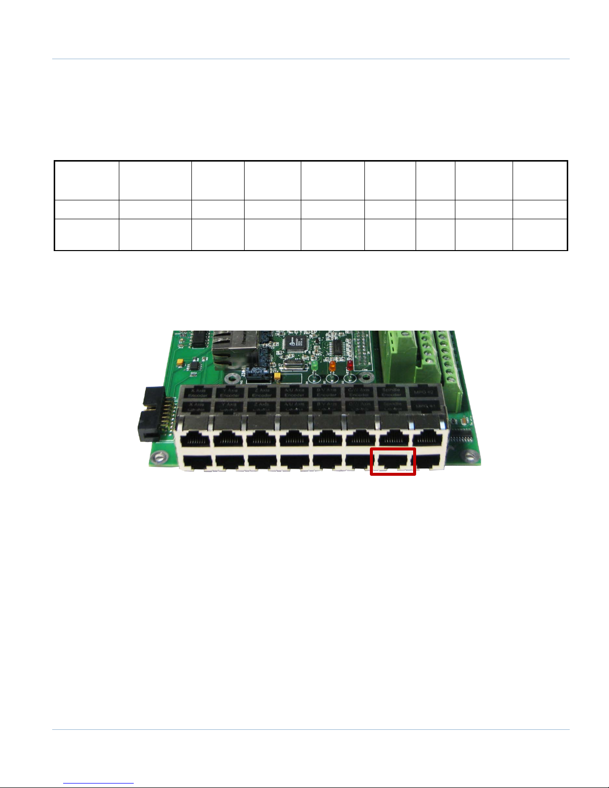
Page | 63
RJ45 Pins
11.1 Wiring a Spindle
11.1.1 VFD
Any VFD can be wired into the Spindle Control RJ45 jack by cutting the end off of a CAT5 cable and wiring the
loose ends to the VFD according the following pin out.
Funcon
Analog 0-
10VDC
1 2 3 4 5 6 7 8
Colors
11.1.2 VFD from MachMotion
The process for setting up a VFD from MachMotion is extremely simple. Simply plug the control cable into the
Spindle Control RJ45 jack located on the bottom row of the large RJ45 jack block.
White &
Orange
CW
Relay
Orange
CW
Relay
White &
Green
TABLE 14 SPINDLE CONTROL RJ45 JACK
Drive
Enable
Blue
White &
GND N/C
Blue
Green
CCW
Relay
White &
Brown
CCW
Relay
Brown
FIGURE 78 SPINDLE CONTROL RJ45 JACK
11.1.3 No VFD
If the system does not use a VFD to control the spindle, wire the spindle into the small green connecter as shown
below. Notice that 24V is wired to the CW and CCW relay contacts on the top row of the green connector.
Apollo III Using Mach3

64 | Page
0-10 CCW
CW GND GND
24V Y2 Y0 C1+ 24V HEN 5EN 24V 5V
Y6 Y4 C2+
CW GND GND Y7 Y5 GND GND Y3 Y1 GND HEN 24EN SOV EXT GNDGND CCW
1 5
A1A2
2
3
4
C
O
M
N
O
N
C
Finder
97.01
11
14
12
COIL
Schneider
LC1D
Contactor
1/L1 3/L2 5/L3
13/NO
21/NC A1
2/T1 4/T2 6/T3
14/NO 22/NC A2
1 5
A1A2
2
3
4
C
O
M
N
O
N
C
Finder
97.01
11
14
12
COIL
Schneider
LC1D
Contactor
1/L1 3/L2 5/L3
13/NO 21/NC A1
2/T1 4/T2 6/T3
14/NO 22/NC A2
Spindle
Contactor Coil AC
Voltage Source
3 Phase
Source
Important!
Schneider Contactors are fitted
with Schneider LAD9R1V
Reversing Switch Kit
11.1.4 Spindle Feedback
The Apollo III takes a 5V encoder signal as spindle feedback. Connect it into the top row of RJ1 as shown below.
FIGURE 79 SPINDLE
FIGURE 80 SPINDLE FEEDBACK RJ45 JACK
Apollo III Using Mach3

Page | 65
RJ45 Pins
The pin out for the spindle feedback RJ45 jack is shown below.
Funcon A+ A- B+ 5V GND B- I+ I-
1 2 3 4 5 6 7 8
Colors
White &
Orange
Orange
White &
Green
TABLE 15 SPINDLE FEEDBACK RJ45 JACK
Blue
White &
Blue
Green
11.2 Configuring the Spindle
11.2.1 Enabling the Spindle
Follow the directions below to enable the spindle inside Mach3.
1. Select Config->Ports and Pins and then click on the Motor Outputs tab
2. Enable all the spindle by setting the spindle box in the column titled Enable to a green check
All the port and pin numbers should be set to 0.
White &
Brown
Brown
3. Now click on the Output Signals tab
4. Enable outputs 1 and 2 and set them up to port 14 pin 6 and port 14 pin 7 respectively as shown below.
Make sure that the Active Low column is set to a red “X” for both outputs.
FIGURE 81 SPINDLE SETUP
Apollo III Using Mach3

66 | Page
Description
Setting
Disable Spindle Relays
Unchecked
Clockwise (M3) Output #
1
CCW (M4) Output #
2
Use Spindle Motor
Checked
PWM Control
Checked
Step/Dir Motor
Unchecked
PWM Base Freq.
100
Minimum PWM
1
FIGURE 82 SPINDLE OUTPUTS
5. Finally, click on the Spindle Setup tab.
TABLE 16 SPINDLE SETTINGS
Apollo III Using Mach3

Page | 67
FIGURE 83 SPINDLE SETUP
6. Press APPLY to save the changes and then OK.
The spindle is now enabled.
11.2.2 Spindle Pulley Setup
For Mach3 to know how to scale the analog voltage output, the maximum RPM for the spindle motor must be
defined. If the machine has different gears Mach3 can have multiple maximum speeds. Mach3 uses a different
pulley for each different speed configuration.
For example, one pulley could be set to 75 to 300 RPM for a low speed (at 300 RPM the control will output
10V). A medium speed pulley could go from 300 to 1200 RPM and high speed pulley could run from 1200 to
2400 RPM.
To change the pulleys, go to Config->Spindle Pulleys. The Pulley Selection window will appear as shown in
Figure 22.
Use the drop down menu titled Current Pulley to select the pulley to be updated. Enter in the maximum and
minimum speeds for each pulley. Then select the current pulley and press OK.
Note: Only set up multiple pulleys if the machine has different gears.
FIGURE 84 PULLEY SPEED SETUP
Apollo III Using Mach3

68 | Page
Note: If the spindle is turning the wrong direction check the reversed box in the Spindle Pulleys window
The pulleys can also be changed by using M41-M45. The macros can be used to just change pulleys in Mach3 or
they can be used to automatically change gears on the machine. Outputs 12-16 are configured to shift between
gears 1 and 5. To shift the machine into neutral, run M40. Open up the macros with the VB Script Editor for more
details.
11.2.3 Analog Calibration
On the Systems tab the spindle voltage can be adjusted by changing the percentage (10-200%). Most systems
will not require this value to be changed. However, if the voltage is not close enough, the percentage adjustment
can be calculated with the following formula:
Analog Spindle Scale % = Commanded Voltage/Actual Voltage*100
FIGURE 85 SPINDLE DAC
11.2.4 RPM Feedback
If the spindle has encoder feedback, set up the Threading section. Set the RPM Sync to Hard Encoder, the RPM
Sync Index to 6, and the RPM to the number of encoder pulses per revolution.
FIGURE 86 SPINDLE FEEDBACK SETTINGS
11.2.5 Servo Spindle Setup
To use a servo axis as a spindle the HiCON plugin will need to be configured as follows:
FIGURE 87 SERVO SPINDLE SETTINGS
Set the Spindle Axis drop down to the axis the servo spindle is connected to and set the Spindle Type to Gcode
Axis.
Apollo III Using Mach3

Page | 69
M-Code
Function
M3
Clockwise
M4
Counter/Clockwise
M5
Stop
Funcon
A+
A-
B+
5V
GND
B-
N/C
N/C
RJ45 Pins
White &
White &
White &
White &
11.2.6 Turning on the Spindle
In addition to the screen controls the spindle can also be controlled using M-codes. Use the table below as a
reference.
TABLE 17 SPINDLE M-CODES
12 MPGS
The Apollo III has two 5V MPG encoder inputs. They are located on RJ1 as shown below.
FIGURE 88 MPG RJ45 JACKS
Below is the pinout for the MPGs:
1 2 3 4 5 6 7 8
Colors
To configure the MPGs open up the HiCON plugin as shown in Error! Reference source not found. on page Error!
Bookmark not defined.. Under the System tab set the MPG type to Encoder Channel. The Index should be set
to 7 for MPG 1 and 8 for MPG 2 as shown below.
Orange
Orange
Green
TABLE 18 MPG RJ45 JACKS
FIGURE 89 MPG PLUGIN SETUP
Blue
Blue
Green
Brown
Brown
Apollo III Using Mach3

70 | Page
Apollo III Using Mach3

Page | 71
Inputs
Jumpers
LEDs
Next, set up the Mach3 software.
1. Open up Config->Ports and Pins and go to the Encoder/MPG’s tab.
2. Enable one of the MPGs by clicking on the red X under the Enabled column. If it has a green check mark
then it is already enabled.
FIGURE 90 MPG 1 ENABLED
3. Set the Counts/Unit to the number of counts per click. On most MPGs this is 4.
4. Press APPLY and then OK.
The MPG is now set up.
13 INPUTS
The Apollo III has 16 configurable inputs. These inputs can be used for limit switches, home switches, tool
changers, or anything else. As shown below, the inputs are located on the main green terminal block, TB1.
FIGURE 91 INPUTS
Apollo III Using Mach3

72 | Page
1 2 3
A-D B-D C-D
C0- C0- C0- C0+ C0+ C0+
X-D Y-D Z-D
C0- C0+ C0+C0- C0- C0- C0+ C0+ C0+
X-S Y-S Z-S X0 X
1 X2
X3 X4 X5 X6 X7 X8X9 X10 X11 X12 X13 X14
X15
C0+ 24VA-S B-S C-S
GND GND GND 5V 5V 5V X0L X1L X0L X3L X4L X5L X6L X7L X8L X9L X10L X11L X12L X13L X14L X15L C0- GND
Each input has an LED that shows the current state of the input. Both the LED and input are labeled with the input
name. The inputs start counting from X0 and up to X15. If the LED is on, then the input is activated. Different
configurations can be selected for each input by using the jumpers near the bottom right of Apollo III. The
jumpers start counting from the left at X0 and increment up to X15. Each jumper corresponds to an input. For
example, the jumper labeled X10 corresponds to the input on TB1 labeled X10 and the LED X10.
FIGURE 92 INPUT JUMPERS
FIGURE 93 JUMPER POSITIONS
WARNING
Input X0 is configured as drive fault by default. If you servo drives from
MachMotion, DO NOT connect anything to X0. It could damage your drives or
Apollo III motion controller.
13.1 Wiring Inputs
13.1.1 Standard 24V Inputs
For a standard 24V input, place the jumper on the bottom two pins. Next, connect C0+ to 24V and C0- to GND
on TB1 as shown below.
FIGURE 94 - 24V CONFIGURATION
Apollo III Using Mach3

Page | 73
A-D B-D C-D
C0- C0- C0- C0+ C0+ C0+
X-D Y-D Z-D
C0- C0+ C0+C0- C0- C0- C0+ C0+ C0+
X-S Y-S Z-S
X0 X1 X2 X3 X4 X5
X6 X7 X8 X9 X10 X11 X12 X13 X14 X15 C0+ 24VA-S B-S C-S
GND GND GND 5V 5V 5V
X0L X1L X0L X3L X4L X5L
X6L X7L X8L X9L X10L X11L X12L X13L X14L X15L C0- GND
Switch
Jumper
position
1
A
-
D B
-D
C
-D
C0
- C
0
- C
0
-
C
0+ C
0+ C0
+
X-
D Y
-
D Z
-D
C0-
C0+
C0+
C0- C0- C0-
C0
+ C
0
+ C
0
+
X-S Y-S Z-S X0
X1
X2
X
3
X4
X5
X
6 X7 X8
X9 X10 X11 X12
X13 X
14
X15
C
0+
24V
A-S B
-S C
-S
GND GND GND 5V 5
V 5
V
X
0L
X1
L
X0
L
X
3L
X4L X5L
X6L X7L X8L X9L
X10L
X11L
X12L
X
13L
X14
L
X
15L
C0
-
GND
+ 48V Supply -
Switch
Jumper
position
1
A-D B-D C-D
C0- C0- C0- C0+ C0+ C0+
X-D Y-D Z-D
C0- C0+ C0+C0- C0- C
0-
C
0+ C0+ C0+
X-S Y-S Z-S X0 X1 X2 X3 X4 X5 X6 X7 X8 X9 X10 X11 X12 X13 X14 X15 C0+ 24VA-S B-S C-S
GND GND GND 5V 5V 5V X0L X1L X0L X3L X4L X5L X6L X7L X8L X9L X10L X11L X12L X13L X14L X15L C0- GND
+ 12V Supply -
PNP Proxy
Jumper
position
1
Then connect the input to the input terminal on the middle row (X1, X2, etc.). See the diagram below.
FIGURE 95 STANDARD 24V INPUT
To activate the input, 24V must be supplied to the input. A floating signal or a ground will not turn on the input.
The LED corresponding to the input will turn on brightly when the input is activated.
13.1.2 High Voltage Sourcing Inputs (PNP)
For 9-48V inputs, supply the positive voltage to the C0+ terminal and connect ground to C0-. Set the jumper for
the input to the bottom two terminals. Then connect the signal into the corresponding input.
For example, the Apollo III shown below is set up for 30V. Notice that input X4 is connected to a switch.
FIGURE 96 - HIGH VOLTAGE SOURCING INPUTS
Note: All the inputs use the same common.
Below is another example with a 12V PNP proxy sensor.
Apollo III Using Mach3
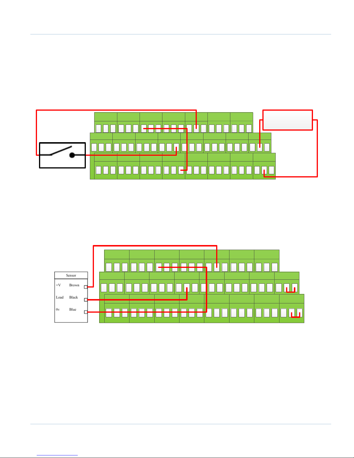
74 | Page
A-
D B
-
D C
-D
C0
-
C0
- C
0
-
C0+ C0+ C0+
X-
D Y
-
D Z
-D
C0
- C0+ C0+
C0
-
C0
- C
0
-
C0+ C0+ C0+
X-
S
Y-
S Z-S
X0 X1 X2 X3 X4 X5 X6 X7 X8 X9 X10 X11 X12 X13
X14X15
C
0+
24V
A-S B-S C-S
GND GND GND 5V 5V 5V X0L X1L X0L X3L X
4
L X
5L
X6L X7L X8L X9L X10L X11L X12L X13L X14L X15L C0- GND
+ 5V Supply -
Switch
Jumper
position
3
A-D B-D C-D
C0- C0- C0- C0+ C0+ C0+
X-D Y-D Z-D
C0- C0+ C0+C0- C0- C0- C0+ C0+ C0+
X-S Y-S Z-S
X0 X1 X2
X3 X4 X5 X6 X7 X8 X9 X10 X11
X12 X13 X14 X15 C0+ 24V
A-S B-S C-S
GND GND GND 5V 5V 5V X0L X1L X0L X3L X4L X5L X6L X7L X8L X9L X10L X11L X12L X13L X14L X15L C0- GND
Jumper
position
2
FIGURE 97 - 12V PROXY EXAMPLE
13.1.3 Low Voltage Sourcing Inputs (PNP)
For 2.5-10V inputs, connect the positive voltage to the C0+ terminal and ground to C0-. Completely remove the
jumper corresponding to the input and connect XNL (where N represents the input number) to GND. Then connect
the signal to the corresponding input.
Assuming that the jumper for X5 has been removed, the example below shows how to wire in a 5V toggle switch.
FIGURE 98 - 5V TOGGLE SWITCH EXAMPLE
Note: The 5V supply could come from TB2 on the Apollo III.
13.1.4 Sinking Inputs (NPN)
For most NPN proxies place the jumper on the top two pins. Then connect the signal into the corresponding input.
See the example below.
FIGURE 99 STANDARD NPN PROXY
If the proxy has an internal pull-up resistor, depending on its size, it could require the jumper to be completely
removed. Use a 3.9k ohm resistor and connect it between XSL and C0+.
Below is an example of a 24V NPN proxy with an internal pull-up resistor. The jumper on the Apollo III must be
completely removed for this to work.
Apollo III Using Mach3
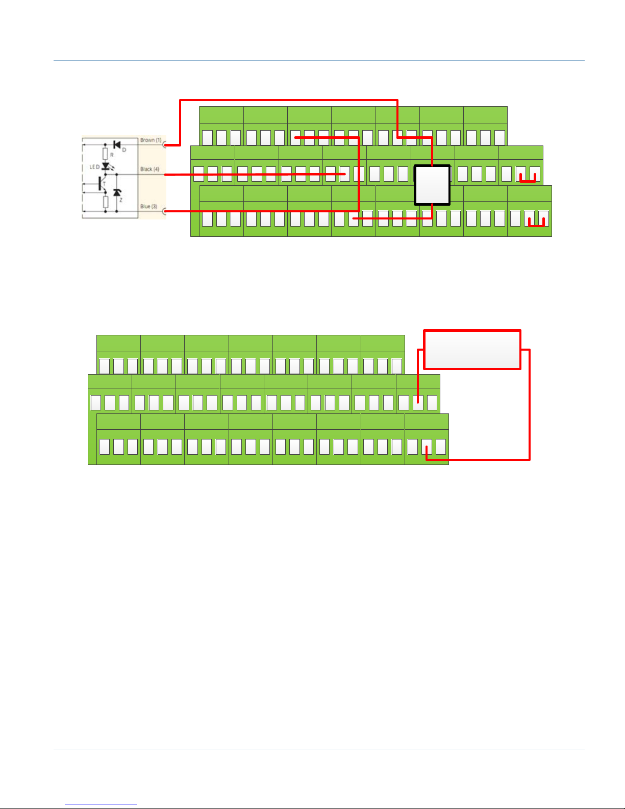
Page | 75
A-D B-D C-D
C0- C0- C0-
C0+ C0+ C0+
X-D Y-D Z-D
C0- C0+ C0+
C0- C0- C0-
C0+ C0+ C0+
X-S Y-S Z-S
X0 X1 X2 X3 X4 X5
X6 X7 X8 X9 X10 X11 X12 X13 X14 X15 C0+ 24VA-S B-S C-S
GND GND GND 5V 5V 5V
X0L X1L X0L X3L X4L X5L X6L X7L X8L
X9L X10L X11L X12L X13L X14L X15L C0- GND
NPN Proxy
3.9k
Ohm
Jumper
position
3
A-D B-D C-D
C0- C0- C0- C0+ C0+ C0+
X
-D Y-D Z-D
C0-
C0+
C0+
C0- C
0-
C0-
C0+ C0+ C0+
X-S Y-S Z-S X0
X1 X2 X3 X4
X5
X6 X7 X8 X9 X10 X11 X12 X13 X
14 X15
C0+
24V
A-S B-S C-S
GND GND GND 5V 5V 5V X0L X1L X0L X3L X4
L X
5L
X
6L X7
L X8L
X9L X10L X11L X12L X13L X14L X15L C0- GND
+ 5V Supply
-
FIGURE 100 NPN PROXY WITH INTERNAL PULLUP
13.1.5 Isolated Inputs
To isolate inputs, supply an external power supply to C0- (GND) and C0+ (positive voltage supply). Do not
power the C0+ with more than 48V. All the other wiring configurations (PNP, NPN, etc) are the same whether or
not the inputs are isolated. In the example below the inputs are isolated using a separate 5V power supply.
13.2 Configuring Inputs
To configure an input in Mach3, follow the procedure below.
6. On the menu bar click on Config->Ports and Pins.
7. Select the Input Signals tab. Scroll down to the desired input. There are 4 inputs and 15 OEM triggers.
An OEM trigger acts exactly like an input.
FIGURE 101 - 5V ISOLATED POWER SUPPLY
Apollo III Using Mach3

76 | Page
FIGURE 102 INPUT CONFIGURATION
8. Enable the input by clicking on the red “X”. If it is a green check mark, it is already enabled.
9. Set the Port Number and Pin Number to the desired input
Note: All input port numbers are 11 and the pin numbers correspond to the X number (X4 would be pin 4)
10. To change when the input is active, click on the Active Low column. A green check mark means that the
input is active low and a red X means that the input is active high.
The input is now be set up.
14 OUTPUTS
The Apollo III has 8 logic outputs that can be used for any low DC current application. They are located on the
small green terminal block as shown below.
Apollo III Using Mach3
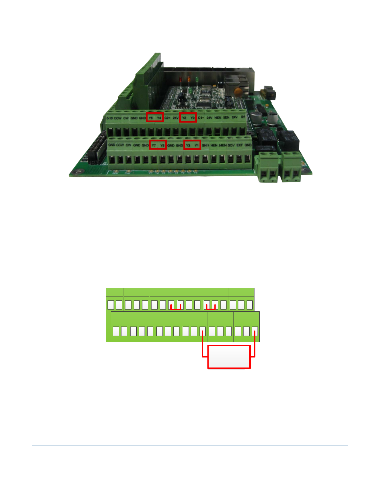
Page | 77
0-10 CCW CW GND GND 24V Y2 Y0 C1+ 24V HEN 5EN 24V 5VY6 Y4 C2+
CW GND GND Y7 Y5 GND GND Y3 Y1 GND HEN
24EN
SOV EXT GNDGND CCW
24V Load
FIGURE 103 OUTPUTS
Each output has an LED that shows its current state. The outputs and LEDs are labeled Y0 through Y7. If the LED is
on, the output is activated.
14.1 Wiring Outputs
There are two separate commons for the outputs. The common C1+ is for outputs Y0-Y3 and C2+ is for Y4-Y7.
Each common can take 7-48VDC. If the outputs being used are using the voltage supply from Apollo III, each
output can only supply 125mA. However, if they are supplied using a separate voltage source, each output can
source up to 250mA.
For standard operation the outputs can have their commons jumpered to 24V on the Apollo III. At that point
simply connect the load to the output and GND. See the figure below.
In the example below, a 10V and 48V supply are used to power the two commons. In this example Y0-Y3 are
48V outputs and Y4-Y7 are 10V outputs.
FIGURE 104 STANDARD 24V 125MA OUTPUTS
Apollo III Using Mach3
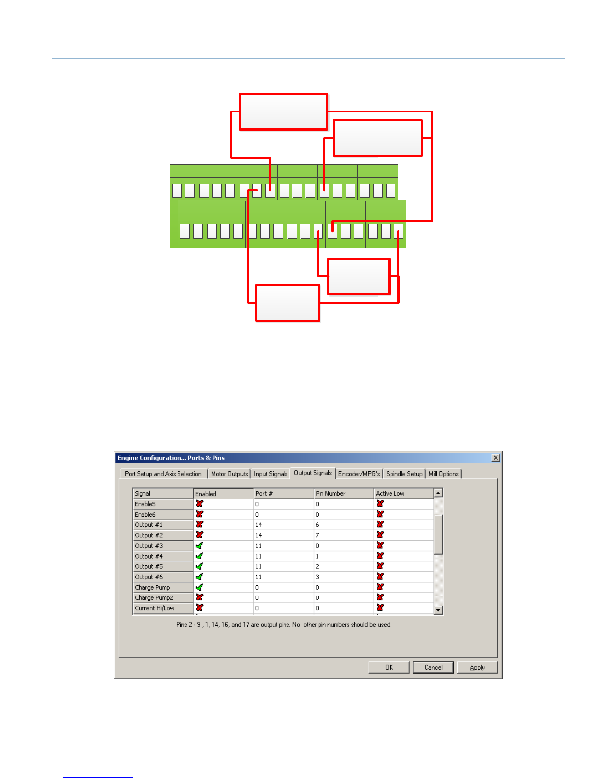
78 | Page
0-10 CCW CW GND GND 24V Y2 Y0 C1+ 24V HEN 5EN 24V 5VY6 Y4 C2+
CW GND GND Y7 Y5 GND GND Y3 Y1 GND HEN
24EN
SOV EXT GNDGND CCW
48V Load
+ 10V Supply -
10V Load
+ 48V Supply -
FIGURE 105 CUSTOM 250MA OUTPUTS
14.2 Configuring Outputs
To configure an output, follow the procedure below.
7. On the menu bar click on Config->Ports and Pins.
8. Select the Output Signals tab.
9. Scroll down to the desired output (There are 20 outputs that can be used).
FIGURE 106 OUTPUT CONFIGURATION
Apollo III Using Mach3

Page | 79
Custom M-Codes
Functions
Default Output
M200
Output 5 on
M201
Output 5 off
M202
Output 6 on
M203
Output 6 off
M204
Output 7 on
M205
Output 7 off
M206
Output 8 on
M207
Output 8 off
M208
Output 9 on
M209
Output 9 off
M210
Output 10 on
M211
Output 10 off
10. Enable the output by setting the Enabled box to a green check.
11. Set the Port Number to 11 and the Pin Number to the corresponding Y number (Y3 would be pin
number 3).
12. Set the Active Low column to a green check for a normally closed signal or red x for normally open.
14.3 Using Outputs
Outputs 5-10 can be controlled with M-Codes. One M-Code turns an output on, and the other M-Code turns the
output off. Use the table below for a reference.
Y2
Y3
Y4
Y5
Y6
Y7
TABLE 19 M-CODES FOR OUTPUTS
Apollo III Using Mach3

80 | Page
Signal
Enabled
Step Pin#
Dir Pin#
Dir Low Active
Step Low Active
Step Port
Dir Port
X Axis
X* 0 0
X
0
0
Y Axis
X* 0 0
X
0
0
Z Axis
X* 0 0
X
0
0
A Axis
X* 0 0
X
0
0
B Axis
X* 0 0
X
0
0
C Axis
X* 0 0
X
0
0
Spindle
0 0 X
0
0
Signal
Enabled
Port #
Pin Number
Active Low
Emulated
HotKey
X++ X 11 1 X X 0
X-- X 11 1 X X 0
X Home
X
11 1 X X 0
Y++ X 11 2 X X 0
Y-- X 11 2 X X 0
Y Home
X
11 2 X X 0
Z++ X 11 3 X X 0
Z-- X 11 3 X X 0
Z Home
X
11 3 X X 0
A++ X 11 4 X X 0
A-- X 11 4 X X 0
A Home
X
11 4 X X 0
B++ X 11 5 X X 0
B-- X 11 5 X X 0
B Home
X
11 5 X X 0
C++ X 11 6 X X 0
15 APPENDICES
15.1 Default Factory Settings
These are not the settings required for the system to function correctly. These are the settings as they come from
the factory before the setup process described above is completed.
15.1.1 Default Motor Outputs
*These will be enabled if drives and motors for these axes were purchased with the control.
15.1.2 Default Input Signals
Table 20 – Default Motor Outputs
Apollo III Using Mach3

C-- X 11 6 X X 0
C Home
X
11 6 X X 0
Estop
14
5 X
0
OEM Trig #1
11 0 X X 0
Signal
Enabled
Port #
Pin Number
Active Low
Digit Trig
X 0 0
X
Enable1
14 0 X
Enable3
14 1 X
Output #1
14 6 X
Output #2
14 7 X
Output #3
11 0 X
Output #4
11 1 X
Output #5
11 2 X
Output #6
11 3 X
Output #7
11 4 X
Output #8
11 5 X
Output #9
11 6 X
Output #10
11 7 X
15.1.3 Default Output Signals
Page | 81
Table 21 – Default Inputs Signals
Table 22 – Default Outputs
Apollo III Using Mach3

82 | Page
**This page intentionally left blank**
Apollo III Using Mach3

83 | Page
15.2 Apollo III Drawing

84 | Page
**This page intentionally left blank**

85 | Page
15.3 Apollo III Case Mount Drawing

86 | Page
**This page intentionally left blank**

87 | Page
16 WARRANTY INFORMATION
MachMotion guarantees all products to be free from manufacturer defects for a period of one year from the
date of purchase. Products which prove to be defective under normal conditions and proper use, during the
warranty period, will be repaired or exchanged free of charge. For warranty service the customer must contact
MachMotion for an RMA number and then return the defective product to MachMotion. If a product is sent to
MachMotion without an RMA number, the product may be misdirected or delayed. When a product or part is
exchanged, any replacement item becomes the customer’s property and the replaced item becomes
MachMotion's property.
If the defect is found to be caused by improper use or installation, the warranty is void. Otherwise the product
will be repaired or exchanged and returned to the address located on the Product Return/Repair Form.
MachMotion will cover ground shipping cost for the replacement/repaired product being returned to the
customer. MachMotion does offer expedited shipping at the customer’s expense.
If a replacement product is needed quickly, a replacement can be sent immediately. In this case the customer will
be charged for the replacement part at the time of the order and be refunded that charge when the defective
component is returned to MachMotion, assuming the defective item falls under the warranty guidelines.
MachMotion will issue a refund within two work weeks after receiving the faulty component.
16.1 Additional Resources
Additional manuals and resources can be found at MachMotion.com
The Mach Motion Team
http://www.machmotion.com
14518 County Road 7240, Newburg, MO 65550
(573) 368-7399 • Fax (573) 341-2672
 Loading...