

Page 1
© Mach III Clutch, Inc. All Rights Reserved
CLICK on product numbers above
to obtain the product detail sheet
which includes dimensional data
helpful during installation.
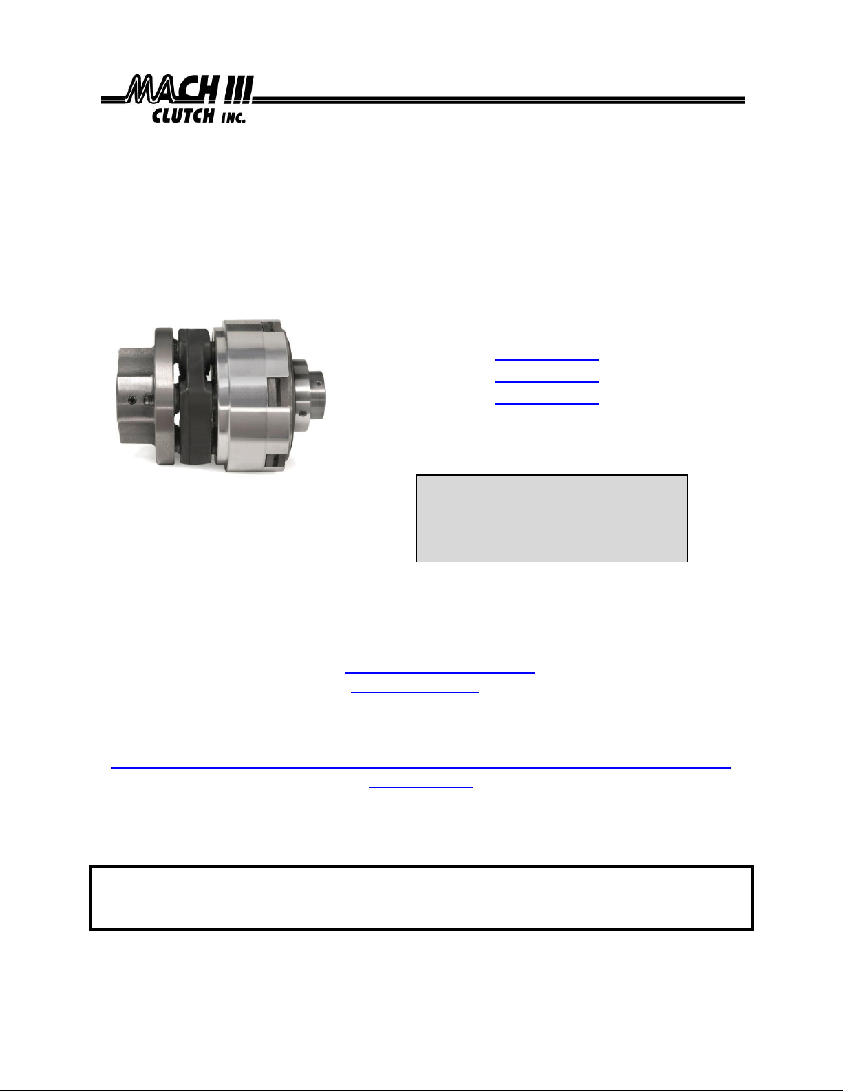
Installation & Maintenance Manual
MECHANICAL FRICTION TORQUE LIMITERS
WITH FLEXIBLE COUPLING
Catalog Products:
T3H2H-STL
T4H2H-STL
T5H2H-STL
T6H1G-STL, T6H1H-STL, T6H2H-STL
And non-catalog variations of this clutch design.
Mach III Technical Support
Toll Free: 866-291-0849
International: 001-859-291-0849
Email: engineering@machiii.com
www.machiii.com
Detail sheets and 3D models are available on the Mach III website:
http://www.machiii.com/Products/Torque-Limiter/Flexible-Mechanical-Torque-Limiter-
Couplings.asp
Please contact Mach III to obtain assembly and parts list drawings.
This product includes rotating equipment and should be guarded according to
OSHA requirements and other Federal, State and local regulations. It is the
responsibility of the user to provide necessary guarding.
7/9/2013 TORQLIM_FLEXCOUPL_MANUAL Page 1 of 5
Page 2
D
B
L
C
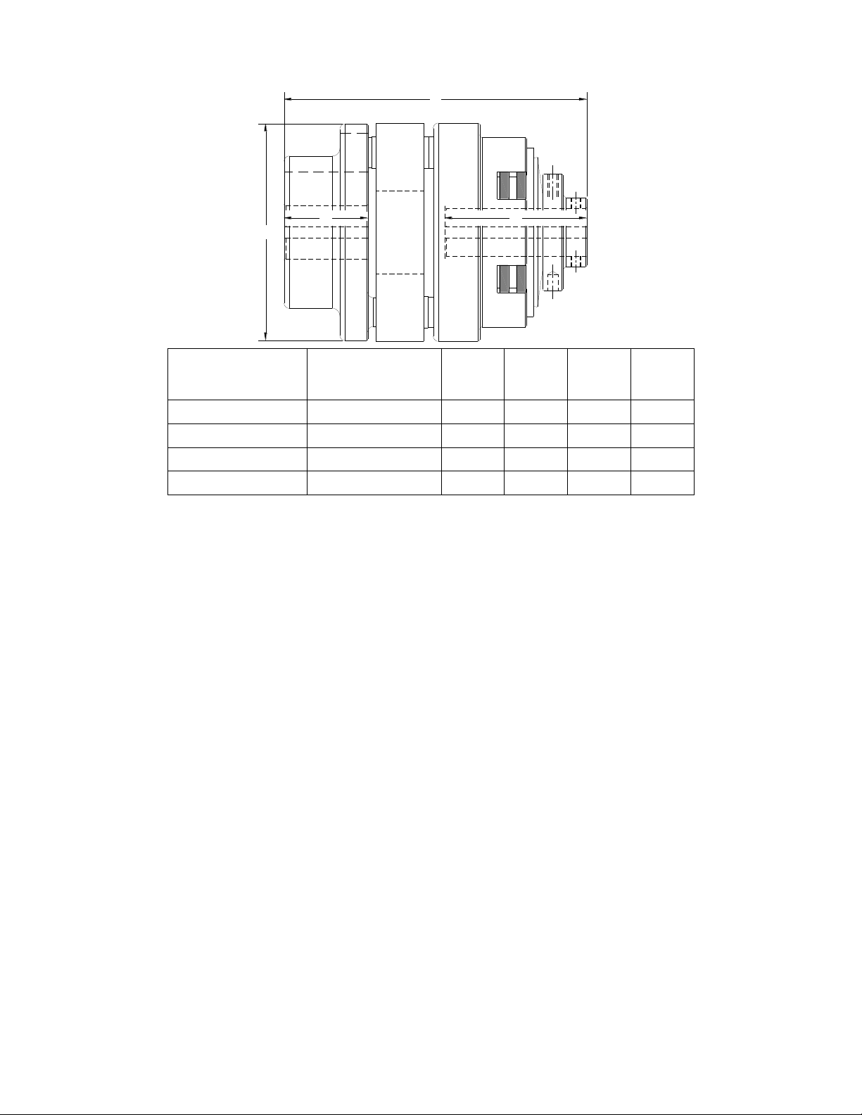
Reference Diagram:
Product#
MAX BORE
WITH
SQUARE KEY
B C D
L
T3H2H-STL
0.875
1.75
2.79
4.00
6.27
T4H2H-STL
1.125
2.06
3.50
5.13
7.44
T5H2H-STL
1.375
2.06
3.75
5.69
7.70
T6H1G-STL
2
2.37
4.25
7.34
9.91
I. Torque Setting
Mach III torque limiters are typically shipped to the customer with the torque value they have
specified. (Note: All torque settings are +/- 10%.) If a torque limiter requires setting or resetting in the field, please refer to section VII of this document.
II. Installation
A. SHAFT PREPARATION & MOUNTING
Mach III Clutch products are bored to fit a precision plug gauge for the specified bore size
and should slide fit the mating shaft. Make certain that the shaft is free of burrs or nicks. It
may be necessary to file or sand the shaft to assure a slide fit. Never hammer the torque
limiter onto the shaft. Hammering on the torque limiter may cause evident damage or subtle
injury that will shorten the wear life of the unit, and will void the warranty.
(1) Apply the anti-seize (E-Z Break®) lubricant from the packet provided, or
equivalent, to the shaft.
(2) Insert key (customer supplied) onto the shaft.
(3) Slide torque limiter over key on the shaft, align the sprocket or pulley.
(4) Tighten set screws to secure the torque limiter to the shaft.
B. FINAL INSPECTION & TESTING
After a short run, check set screws and alignment.
III. Operation:
This is a manually adjusted torque limiter. Torque is proportional to the amount of spring
compression.
Special Note Regarding Friction Disc Contamination:
The friction material used in this product will absorb oil, water, chemicals and other
contaminants. Depending on the type of contamination, torque limiter may either seize up
entirely or lose torque capacity. If friction discs become contaminated, they should be
replaced. See repair kit ordering information below.
7/9/2013 TORQLIM_FLEXCOUPL_MANUAL Page 2 of 5
Page 3

SET SCREW
SET SCREW
DRIVE DISCS
FRICTION DISCS
SPRING
SET SCREW
NUT
ELASTOMERIC ELEMENT
COUPLING
SET SCREWS
W/JAM NUT (some models)
Kits Available
Contents
Part Numbers
Facing Kit
Friction Disc
T3H2H-STL-FCGK, T4H2H-STL-FCGK, Etc. . . .
Repair Kit
Friction Disc, Spring(s)
T3H2H-STL-RPRK, T4H2H-STL-RPRK, Etc. . . .
Tools Needed
Hex wrench set
Retainer (snap) ring pliers
Spanner Wrench
Compounds Required
Anti-Seize Lubricant
IV. Routine Maintenance
When installed and operated according to the preceding guidelines, Mach III Clutch products
should require little or no routine maintenance. A repair kit is available which contains all
parts subject to typical wear: friction discs, springs.
V. Parts Diagram
For part numbers of components not included in the kits above, please contact Mach III Clutch,
Inc. or your distributor. Factory repair is also available. A return materials authorization (RMA)
number must be obtained prior to sending any unit in for repair. Mach III Clutch is not
responsible for products returned without authorization.
VI. Repair Kit Installation Procedure
7/9/2013 TORQLIM_FLEXCOUPL_MANUAL Page 3 of 5
A. DISASSEMBLY
Loosen set screws using appropriate hex wrench and slide the clutch off of the shaft. Place the
clutch on a work surface with the adjustment nut facing upward. Loosen the set screw in the
adjustment nut and set screws and jam nuts (some models) and remove nut using a wrench or
channel lock pliers. The spring, drive discs and friction discs can now be removed.
Page 4

A
B
C
D
E
B. DRIVE SURFACE INSPECTION & FRICTION DISC REPLACEMENT
Inspect the surface of the steel or iron dive discs. This surface must be free from grooves, burrs
and foreign materials in order for the clutch to operate properly. If damage is pronounced,
please contact Mach III Clutch or your distributor about replacing the drive discs. In addition,
clutch should be inspected for discoloration (turning blue). If discoloration is present, the unit is
being operated beyond its capacity and Mach III Clutch should be contacted for assistance.
C. INSPECTION OF BEARINGS
Check bearings for external damage (missing seals, etc.). Make sure the bearings rotate freely
and smoothly by hand. If bearing replacement is necessary, consult Mach III or your distributor
for the bearing sizes and replacement procedures.
D. REASSEMBLY
Place drive discs, friction discs and spring over drive hub in their proper order making sure they
slide freely on the hub and in the slots. Replace adjustment nut with the shoulder fitting into the
bore of the spring. Adjust torque and tighten set screw.
See “torque Limiter Installation” portion of these instructions for the proper procedure for
reinstalling the clutch.
VII. Torque Setting Instructions
A. Product Numbers: T3H2H-STL, T4H2H-STL, T5H2H-STL and non-catalog
variations of this torque limiter design.
(1) Make sure the nylon-tipped set screw (REF. C) in the outside diameter of the adjustment nut
(REF. A) is loose.
(2) Make sure the adjustment nut (REF. A) is snug against the disc spring (REF. B).
(3) Using a spanner wrench, tighten the adjustment nut (REF. A) against the disc spring
(4) Check torque value after each 1/4-turn increment of the adjustment nut (REF. A) while holding
adapter/sleeve (REF. D) stationary and turning drive hub (REF. E) with a torque wrench.
(5) Tighten the nylon-tipped set screw (REF. C) in the outside diameter of the adjustment nut
(REF. A).
7/9/2013 TORQLIM_FLEXCOUPL_MANUAL Page 4 of 5
Page 5

B. Product Numbers: T6H1G-STL, T6H1H-STL, T6H2H-STL and non-catalog
A
B
C
D
E
F
G
variations of this torque limiter design.
(1) Make sure the adjustment nut (REF. A) is snug against the disc spring (REF. B).
(2) Make sure the six jam nuts (REF. C) mounted on the six set screws (REF. D) which are placed axially
in adjustment nut (REF. A) are loose.
(3) Screw the six set screws (REF. D) in the adjustment nut (REF. A) until they contact the disc spring
(REF. B).
(4) Using a circular pattern, tighten the six set screws (REF. D) in the adjustment nut (REF. A) one 1/4-
turn each.
NOTE: If needed, fine tune the torque value of the unit in 1/8-turn increments of the six set screws
(REF. D).
(5) Check torque value after each 1/4-turn increment of all six set screws (REF. D) while holding
adapter/sleeve (REF. F) stationary and turning drive hub (REF. G) with a torque wrench.
NOTE: A torque wrench with a multiplier may be needed for higher torque settings.
(6) Once desired torque is reached, confirm each of the six set screws (REF. D) are in contact with the
disc spring (REF. B).
(7) Tighten the jam nuts (REF. C) mounted on the six set screws (REF. D) firmly against the adjustment
nut (REF. A).
(8) Tighten the nylon-tipped set screw (REF. E) in the outside diameter of the adjustment (REF. A).
Technical assistance is available by contacting Mach III Clutch, Inc.
Mach III Product Warranty
http://www.machiii.com/Resources/Warranty-Info.asp
Mach III Clutch, Inc.
101 Cummings Drive ● Walton, KY 41094
Toll free 866.291.0849 ● International 859.291.0849 ● Fax 859.655.8362
info@machiii.com ● engineering@machiii.com ● www.machiii.com
7/9/2013 TORQLIM_FLEXCOUPL_MANUAL Page 5 of 5
 Loading...