

Page 1
CLICK on product numbers above
to obtain the product detail sheet
which includes dimensional data
helpful during installation.
Installation & Maintenance Manual
MECHANICAL FRICTION TORQUE LIMITERS
THROUGH SHAFT MOUNT – BRONZE BUSHING PILOT
Catalog Products:
T3B2H-STL
T4B2H-STL
T5B2H-STL
T6B1G-STL, T6B1H-STL, T6B2H-STL
And non-catalog variations
of this torque limiter design.
Mach III Technical Support
Toll Free: 866-291-0849
International: 001-859-291-0849
Email: engineering@machiii.com
www.machiii.com
Detail sheets and 3D models are available on the Mach III website:
http://www.machiii.com/Products/Torque-Limiter/Pilot-Mount-Torque-Limiters-Bronze-
Bushing.asp
Please contact Mach III to obtain assembly and parts list drawings.
This product includes rotating equipment and should be guarded according to
OSHA requirements and other Federal, State and local regulations. It is the
responsibility of the user to provide necessary guarding.
7/27/2013 TORQLIM_BRNZBUSH_MANUAL Page 1 of 5
© Mach III Clutch, Inc. All Rights Reserved
Page 2

I. Torque Setting
Mach III torque limiters are typically shipped to the customer with the torque value they have
specified. (Note: All torque settings are +/- 10%.) If a torque limiter requires setting or resetting in the field, please refer to section VIII of this document.
II. Installing a Sprocket or Pulley
Mach III units are typically shipped from the factory with the required sprocket or pulley
preinstalled. This section pertains only to those who need to install or replace a pulley or
sprocket in the field. Please use the links on page one of this document to obtain the
detail sheet for your unit. This sheet will include the pilot diameter and other dimensions
needed to machine the sprocket or pulley.
Bore the sprocket or pulley for clearance (slide fit) over pilot and drill standard clearance
holes for the number and type of screws on corresponding bolt circle. The cap screws
used to attach the sprocket or pulley should not be longer than the sum of the depth of
the threaded hole plus the thickness of the sprocket or pulley. Otherwise, the cap screws
may bottom out. Tighten all screws to uniform torque based on screw size and use
proper Loctite® (or equivalent) compound to assure a permanent mount.
III. Torque Limiter Installation
A. SHAFT PREPARATION & MOUNTING
Mach III Clutch products are bored to fit a precision plug gauge for the specified bore size and
should slide fit the mating shaft. Make certain that the shaft is free of burrs or nicks. It may be
necessary to file or sand the shaft to assure a slide fit. Never hammer the torque limiter onto
the shaft. Hammering on the torque limiter may cause evident damage or subtle injury that will
shorten the wear life of the unit, and will void the warranty.
(1) Apply the anti-seize (E-Z Break®) lubricant from the packet provided, or equivalent, to
the shaft.
(2) Insert key (customer supplied) onto the shaft.
(3) Slide torque limiter over key on the shaft, align the sprocket or pulley.
(4) Tighten set screws to secure the torque limiter to the shaft.
B. FINAL INSPECTION & TESTING
Check alignment of the sprocket or pulley. After a short run, check set screws and alignment.
IV. Torque Limiter Operation
This is a manually adjusted torque limiter. Torque is proportional to the amount of spring
compression.
Special Note Regarding Friction Disc Contamination:
The friction material used in this product will absorb oil, water, chemicals and other
contaminants. Depending on the type of contamination, torque limiter may either seize
up entirely or lose torque capacity. If friction discs become contaminated, they should be
replaced. See repair kit ordering information below.
V. Routine Maintenance
When installed and operated according to the preceding guidelines, Mach III Clutch
products should require little or no routine maintenance. A repair kit is available which
contains all parts subject to typical wear: friction discs, springs.
7/27/2013 TORQLIM_BRNZBUSH_MANUAL Page 2 of 5
Page 3
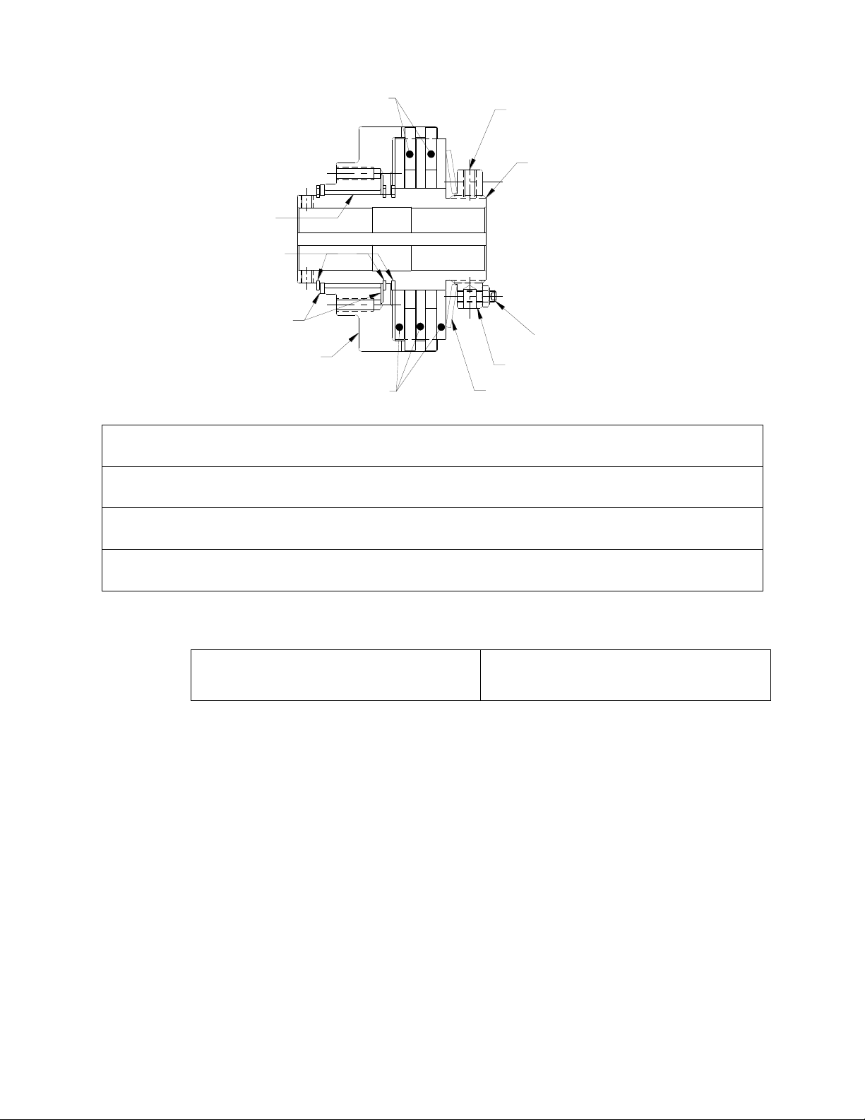
RACE
BUSHING
RETAINER RING
DRIVE DISC
SLEEVE
FRICTION DISC
DRIVE HUB
NYLON PT.
SET SCREW
SPRING
NUT
SET SCREWS
W/JAM NUT (some models)
VI. Parts diagram
Repair Kit:
Part number = Clutch Product Number + “-RPRK” (e.g. T3B2H-STH-RPRK)
Facing Kit:
Part number = Clutch Product Number + “-FCGK” (e.g. T3B2H-STH-FCGK)
Additional
Parts:
Contact Mach III to obtain a complete listing of additional parts kits available for
your specific clutch. Please reference product number when calling or e-mailing.
Repair
services:
Factory repair is available. A return materials authorization (RMA) number must
be obtained prior to sending any unit in for repair
Tools Required
Hex Wrench Set
Retainer (snap) Ring Pliers
Compounds Required
Anti-Seize Lubricant (for re-installation)
VII. Repair Kit Installation Procedure
A. DISASSEMBLY
(1) Remove torque limiter from shaft and place in vertical position with nut end facing
upward.
(2) Loosen nylon point set screw, set screws and jam nuts (some models) and remove nut.
Drive hub will need to be held stationary for this procedure.
(3) The disc package (consisting of spring, drive discs and friction discs) will now be
accessible.
B. FRICTION DISC & SPRING REPLACEMENT
(1) Remove the spring, drive discs and friction discs.
(2) Drive discs should be clean, dry and free of burrs or nicks.
(3) Reassemble drive & friction disc section according to reference drawing using new
spring, drive discs & friction discs as necessary.
(4) Assure that drive discs move freely on the drive hub and that the lugs of the friction disc
discs move freely in the drive slots of the sleeve.
7/27/2013 TORQLIM_BRNZBUSH_MANUAL Page 3 of 5
Page 4
A
B
C
D
E
C. REASSEMBLY
(1) Replace the nut.
(2) Adjust to desired torque.
(3) Tighten nylon point set screw.
(4) See “torque Limiter Installation” portion of these instructions for the proper procedure
for reinstalling the clutch.
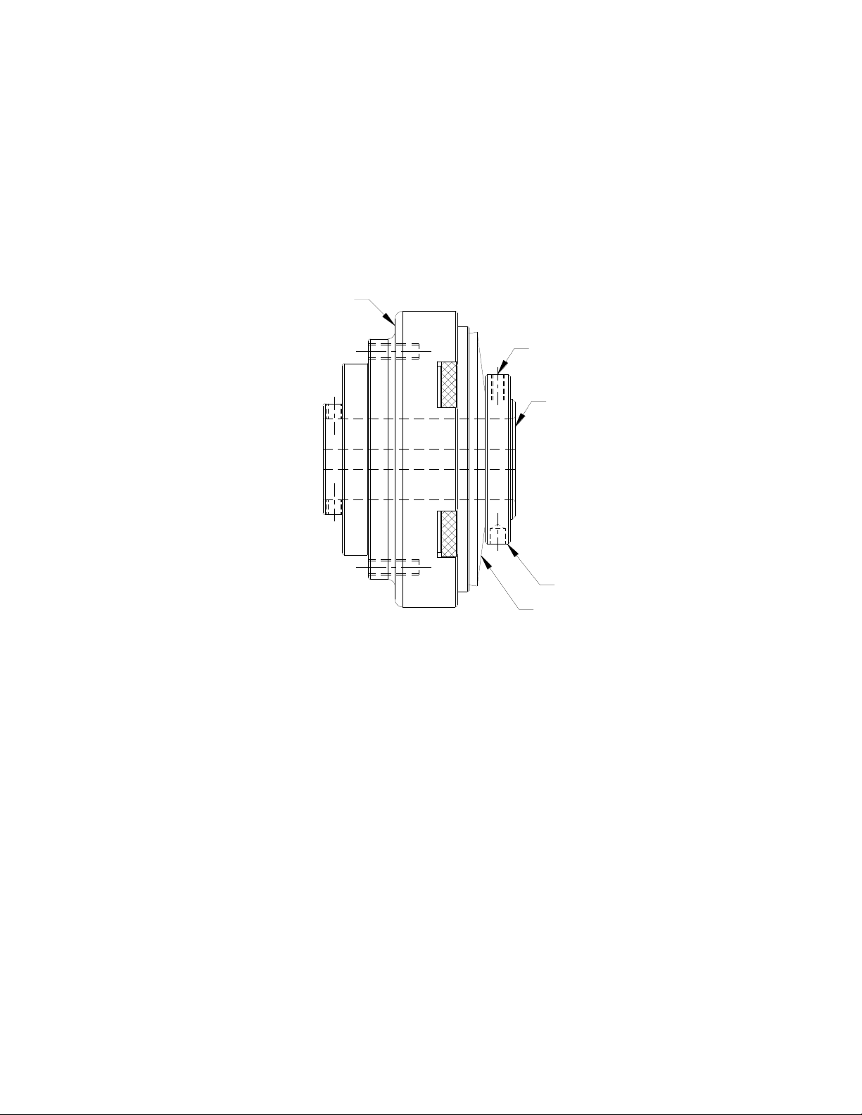
VIII. Torque Setting Instructions
A. Product Numbers: T3B2H-STL, T4B2H-STL, T5B2H-STL and non-catalog
variations of this torque limiter design.
(1) Make sure the nylon-tipped set screw (REF. C) in the outside diameter of the adjustment nut
(REF. A) is loose.
(2) Make sure the adjustment nut (REF. A) is snug against the disc spring (REF. B).
(3) Using a spanner wrench, tighten the adjustment nut (REF. A) against the disc spring
(4) Check torque value after each 1/4-turn increment of the adjustment nut (REF. A) while holding
adapter/sleeve (REF. D) stationary and turning drive hub (REF. E) with a torque wrench.
(5) Tighten the nylon-tipped set screw (REF. C) in the outside diameter of the adjustment nut
(REF. A).
7/27/2013 TORQLIM_BRNZBUSH_MANUAL Page 4 of 5
Page 5

B. Product Numbers: T6B1G-STL, T6B1H-STL, T6B2H-STL and non-catalog
A
B
C
D
E
F
G
variations of this torque limiter design.
(1) Make sure the adjustment nut (REF. A) is snug against the disc spring (REF. B).
(2) Make sure the six jam nuts (REF. C) mounted on the six set screws (REF. D) which are placed axially in
adjustment nut (REF. A) are loose.
(3) Screw the six set screws (REF. D) in the adjustment nut (REF. A) until they contact the disc spring (REF.
B).
(4) Using a circular pattern, tighten the six set screws (REF. D) in the adjustment nut (REF. A) one 1/4-turn
each.
NOTE: If needed, fine tune the torque value of the unit in 1/8-turn increments of the six set screws (REF. D).
(5) Check torque value after each 1/4-turn increment of all six set screws (REF. D) while holding
adapter/sleeve (REF. F) stationary and turning drive hub (REF. G) with a torque wrench.
NOTE: A torque wrench with a multiplier may be needed for higher torque settings.
(6) Once desired torque is reached, confirm each of the six set screws (REF. D) are in contact with the disc
spring (REF. B).
(7) Tighten the jam nuts (REF. C) mounted on the six set screws (REF. D) firmly against the adjustment nut
(REF. A).
(8) Tighten the nylon-tipped set screw (REF. E) in the outside diameter of the adjustment (REF. A).
Technical assistance is available by contacting Mach III Clutch, Inc.
Mach III Product Warranty
http://www.machiii.com/Resources/Warranty-Info.asp
Mach III Clutch, Inc.
101 Cummings Drive ● Walton, KY 41094
Toll free 866.291.0849 ● International 859.291.0849 ● Fax 859.655.8362
info@machiii.com ● engineering@machiii.com ● www.machiii.com
7/27/2013 TORQLIM_BRNZBUSH_MANUAL Page 5 of 5
 Loading...