

Page 1
CLICK on product numbers
above to obtain the product detail
sheet which includes dimensional
data helpful during installation.
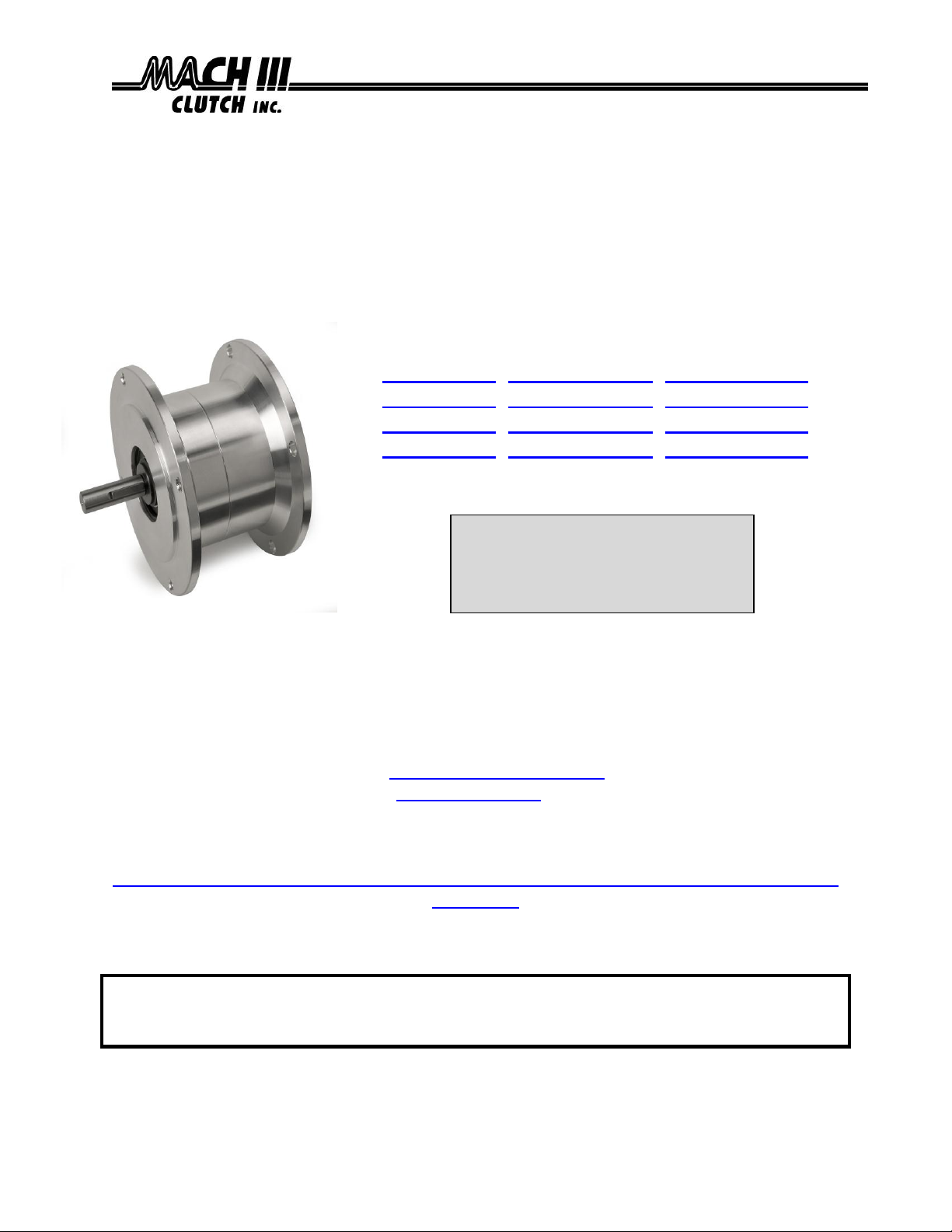
Installation & Maintenance Manual
NEMA FRAME MECHANICAL FRICTION TORQUE LIMITERS
Catalog Products:
T3C2H-56L, T3C2H-56LCA, T3C2H-56LSS
T3C2H-14L, T3C2H-14LCA, T3C2H-14LSS
T4C2H-18L, T4C2H-18LCA, T4C2H-18LSS
T4C2H-21L, T4C2H-21LCA, T4C2H-21LSS
And non-catalog variations of this torque limiter design.
Mach III Technical Support
Toll Free: 866-291-0849
International: 001-859-291-0849
Email: engineering@machiii.com
www.machiii.com
Detail sheets and 3D models are available on the Mach III website:
http://www.machiii.com/Products/Torque-Limiter/NEMA-Frame-Torque-Limiters-C-Face-
Mount.asp
Please contact Mach III to obtain assembly and parts list drawings.
This product includes rotating equipment and should be guarded according to
OSHA requirements and other Federal, State and local regulations. It is the
responsibility of the user to provide necessary guarding.
7/9/2013 TORQLIM_NEMA_MANUAL Page 1 of 5
© Mach III Clutch, Inc. All Rights Reserved
Page 2

I. Torque Setting
Mach III torque limiters are typically shipped to the customer with the torque value they have
specified. (Note: All torque settings are +/- 10%.) If a torque limiter requires setting or resetting in the field, please refer to section VII of this document.
II. Torque Limiter Installation
A. SHAFT PREPARATION & MOUNTING
Mach III Clutch products are bored to fit a precision plug gauge for the specified bore size and
should slide fit the mating shaft and key. Make certain that the shaft is free of burrs or nicks. It
may be necessary to file or sand the shaft or key to assure a slide fit.
Never hammer the torque limiter onto the shaft. Hammering on the torque limiter may cause
evident damage or subtle injury that will shorten the wear life of the unit, and will void the
warranty.
(1) Apply the anti-seize (E-Z Break®) lubricant from the packet provided, or equivalent, to
the shaft.
(2) Insert key (customer supplied) onto the shaft.
(3) Slide torque limiter over key on the shaft.
(4) Tighten flange with cap screws (customer supplied) to motor frame.
(5) Tighten set screw via set screw access hole to secure the key on the shaft.
(6) The torque limiter mounts between a motor and gear reducer. These units are not
suitable for belt drive (pulley output) applications. Consult factory for options.
B. FINAL INSPECTION & TESTING
After a short run, check set screws and alignment.
III. Torque Limiter Operation
This is a manually adjusted torque limiter. Torque is proportional to the amount of spring
compression. This is a friction device and should be monitored for slip. The torque
limiter will burn up if allowed to slip for an extended period of time.
Special Note Regarding Friction Disc Contamination:
The friction material used in this product will absorb oil, water, chemicals and other
contaminants. Depending on the type of contamination, torque limiter may either seize
up entirely or lose torque capacity. If friction discs become contaminated, they should be
replaced. See repair kit ordering information below.
IV. Routine Maintenance
When installed and operated according to the preceding guidelines, Mach III Clutch
products should require little or no routine maintenance. A repair kit is available which
contains all parts subject to typical wear: friction discs, springs.
7/9/2013 TORQLIM_NEMA_MANUAL Page 2 of 5
Page 3

DRIVE HUB
SPRING
FRICTION DISC
RETAINER RING
FEMALE HUB
DRIVE DISC
LOCKING SCREW
SCREW
BEARING
SET SCREW
SET SCREW ACCESS
ADJUSTMENT NUT
V. Parts Diagram
Repair Kit:
Part number = Product Number + “-RPRK” (e.g. T3C2H-56L-RPRK)
Facing Kit:
Part number = Product Number + “-FCGK” (e.g. T3C2H-56L-FCGK)
Additional
Parts:
Contact Mach III to obtain a complete listing of additional parts kits available for
your specific torque limiter. Please reference product number when calling or e-
mailing.
Repair
services:
Factory repair is available. A return materials authorization (RMA) number must
be obtained prior to sending any unit in for repair
Tools Required
Hex Wrench Set
Rubber Mallet or similar soft face hammer
Retainer (snap) Ring Pliers
Scraper
Spanner Wrench
Compounds Required
Loctite® #609 Retaining Compound
Anti-Seize Lubricant (for re-installation)
VI. Repair Kit Installation Procedure
A. DISASSEMBLY
7/9/2013 TORQLIM_NEMA_MANUAL Page 3 of 5
(1) Loosen set screws and remove reducer from torque limiter and torque limiter from
motor.
(2) Remove (3) screws from torque limiter case and separate halves.
(3) Remove retainer ring from drive hub.
(4) Using a soft mallet remove drive hub from bearing.
(5) Loosen locking screw and remove nut. Drive hub will need to be held stationary for this
procedure.
(6) The disc package (consisting of spring, drive discs and friction discs) will now be
accessible.
Page 4

MOUNTING
HOLES
G
D
C
F
E
B
A
H
B. FRICTION DISC & SPRING REPLACEMENT
(1) Remove the spring, drive discs and friction discs.
(2) Drive discs should be clean, dry and free of burrs or nicks.
(3) Reassemble drive & friction disc section according to reference drawing using new
spring, drive discs & friction discs as necessary.
(4) Assure that drive discs move freely on the drive hub and that the lugs of the friction disc
discs move freely in the drive slots of the sleeve.
C. REASSEMBLY
(1) Replace the spring and nut.
(2) Adjust to desired torque by placing the tabs of the friction discs into the slots of the
female hub which should be attached to a fixed shaft. A torque wrench can be attached
to the drive hub and adjustments to the nut should be made until the desired torque is
achieved.
(3) Tighten locking screw in adjustment nut.
(4) Insert drive hub into bearing using Loctite® #609 retaining compound on inner race of
the bearing (if needed old Loctite® can be removed using a scraper) and replace
retainer ring.
(5) Place housing halves back together and reinstall the 3 cap screws.
(6) See “Torque Limiter Installation” portion of these instructions for the proper procedure
for reinstalling to the motor.
VII. Torque Setting Instructions
(1) Remove the (3) socket head cap screws (REF. A) from the female adapter (REF. B).
(2) Separate the two halves of the torque limiter.
(3) Remove the retainer ring (REF. C) from the drive hub (REF. D).
(4) Using a non-marring mallet, remove the drive hub from the male adapter (REF. E).
Note: Using a press to remove the drive hub is also acceptable.
7/9/2013 TORQLIM_NEMA_MANUAL Page 4 of 5
Page 5

TORQUE SETTING INSTRUCTIONS (CONTINUED)
(5) Loosen the nylon-point set screw (REF. F) in the adjustment nut (REF. G).
(6) Place the female adapter assembly in a fixture so that the sleeve (REF. H) cannot rotate.
(7) Place the drive hub assembly in the female adapter assembly so that the adjustment nut (REF.
G) faces upward and the friction lugs drop into the mating cut outs in the sleeve (REF. H).
(8) Using a spanner wrench, either tighten (clockwise direction) the adjustment nut (REF. G) to
increase torque or loosen (counter-clockwise direction) the adjustment nut (REF. G) to
decrease torque.
(9) Check the torque value after each 1/4 turn of the adjustment nut (REF. G) while holding the
drive hub assembly in the sleeve (REF. H) using a torque wrench.
(10) Once the desired torque is reached is, tighten the nylon-point set screw (REF. F) in the
adjustment nut (REF. G).
(11) Insert the drive hub assembly back into the male adapter (REF. E) bearing using Loctite #609
compound on the inner race of the bearing. If any old Loctite remained on the drive hub (REF.
D) or the male adapter (REF. E) bearing, remove it with a scrapper.
(12) Replace the drive hub (REF. D) retainer ring (REF. C).
(13) Join both halves of the torque limiter back together. Be sure that the mounting holes are
positioned so they are aligned with one another.
(14) Reinstall the (3) socket head cap screws (REF. A) into the female adapter (REF. B).
Technical assistance is available by contacting Mach III Clutch, Inc.
Mach III Product Warranty
http://www.machiii.com/Resources/Warranty-Info.asp
Mach III Clutch, Inc.
101 Cummings Drive ● Walton, KY 41094
Toll free 866.291.0849 ● International 859.291.0849 ● Fax 859.655.8362
info@machiii.com ● engineering@machiii.com ● www.machiii.com
7/9/2013 TORQLIM_NEMA_MANUAL Page 5 of 5
 Loading...