

Page 1
CLICK on product numbers
above to obtain the product detail
sheet which includes dimensional
data helpful during installation.
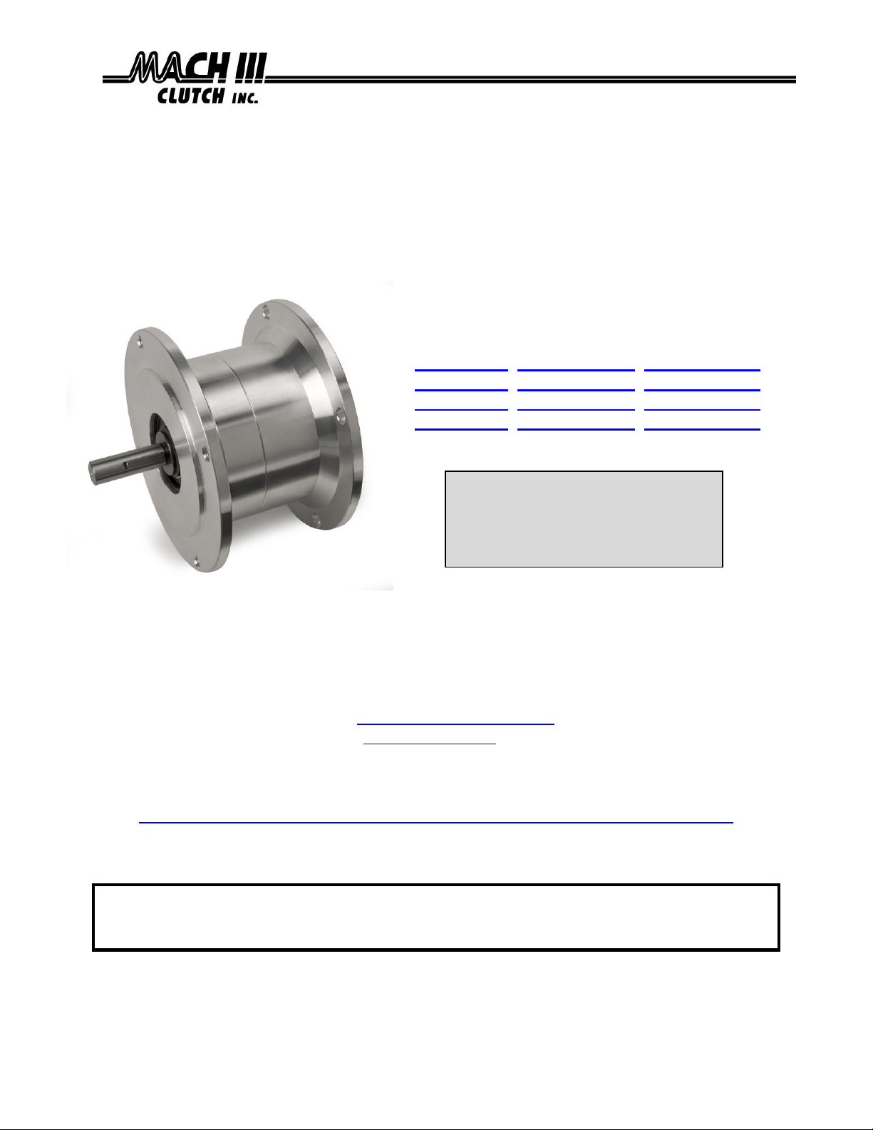
Installation & Maintenance Manual
NEMA FRAME AIR ENGAGED FRICTION CLUTCHES
Catalog Products:
C3C2R-14H, C3C2R-14HCA, C3C2R-14HSS
C3C2R-56H, C3C2R-56HCA, C3C2R-56HSS
C5C2R-18H, C5C2R-18HCA, C5C2R-18HSS
C5C2R-21H, C5C2R-21HCA, C5C2R-21HSS
And non-catalog variations of this clutch design.
Mach III Technical Support
Toll Free: 866-291-0849
International: 001-859-291-0849
Email: engineering@machiii.com
www.machiii.com
Detail sheets and 3D models are available on the Mach III website:
http://www.machiii.com/Products/Clutches/NEMA-Frame-Clutches-C-Face.asp
Please contact Mach III to obtain assembly and parts list drawings.
This product includes rotating equipment and should be guarded according to
OSHA requirements and other Federal, State and local regulations. It is the
responsibility of the user to provide necessary guarding.
7/9/2013 CLUTCH_NEMA_AIR_MANUAL Page 1 of 4
© Mach III Clutch, Inc. All Rights Reserved
Page 2

I. New Clutch Torque
New clutch torque is approximately 40% less than rated design torque until the friction
and drive discs are worn in (lapped, burnished). The length of time for wear-in to occur
depends upon the application.
II. Clutch Installation
A. SHAFT PREPARATION
Mach III Clutch products are bored to fit a precision plug gauge for the specified bore size and
should slide fit the mating shaft. Make certain that the shaft is free of burrs or nicks. It may be
necessary to file or sand the shaft to assure a slide fit. Never hammer the brake onto the
shaft. Hammering on the brake may cause evident damage or subtle injury that will shorten the
wear life of the unit, and will void the warranty.
(1) Apply the anti-seize (E-Z Break®) lubricant from the packet provided, or equivalent, to
the shaft.
(2) Insert key (customer supplied) onto the shaft.
(3) Slide brake over key on the shaft.
B. MOUNTING
The clutch mounts between a motor and gear reducer. These units are not suitable for belt drive
(pulley output) applications. Consult factory for options.
C. AIR LINE CONNECTION
Refer to the dimensional spec sheet for NPT size to obtain correct fitting. Install fitting using a
thread sealing compound to prevent air leakage. Connect an air line to the fitting. Air supply
should be both filtered and regulated. Contamination in the air supply may damage the clutch.
D. FINAL INSPECTION & TESTING
Cycle the clutch with the machine off to check for air leaks and to ensure proper engagement and
release. After a short run, check mounting screws.
III. Clutch Operation
The maximum operating pressure should not exceed 80 PSI. Operation at pressures greater
than that required for proper function will decrease the life of the bearings.
Special Note Regarding Friction Disc Contamination:
The friction material used in this product will absorb oil, water, chemicals and other
contaminants. Depending on the type of contamination, brake may either seize up
entirely or lose torque capacity. If friction discs become contaminated, they should be
replaced. See repair kit ordering information below. If application requires exposure to
contamination consult factory for optional covers.
IV. Routine Maintenance
When installed and operated according to the preceding guidelines, Mach III clutch
products should require little or no routine maintenance. A repair kit is available which
contains all parts subject to typical wear: friction discs, springs and O-rings.
7/9/2013 CLUTCH_NEMA_AIR_MANUAL Page 2 of 4
Page 3

CYLINDER
RETAINER RING [CYLINDER]
RETAINER RING [DISCS]
DRIVE HUB
PIN
O-RING
BEARING
SCREW
SET SCREW
SET SCREW
ACCESS HOLE
[PLUGGED]
FRICTION DISC
DRIVE DISC
SCREW
CONE
PISTON
SPRING
Repair Kit:
Part number = Clutch Product Number + “-RPRK” (e.g. C3C2R-56H-RPRK)
Additional
Parts:
Contact Mach III to obtain a complete listing of additional parts kits available for
your specific brake. Please reference product number when calling or e-mailing.
Repair
services:
Factory repair is available. A return materials authorization (RMA) number must
be obtained prior to sending any unit in for repair
Tools Required
Hex Wrench Set
Rubber Mallet or similar soft face hammer
Retainer (snap) Ring Pliers
Scraper
Compounds Required
Grease
O-ring Lubricant
Loctite® #609 Retaining Compound
Anti-Seize Lubricant (for re-installation)
V. Parts diagram
VI. Repair Kit Installation Procedure
A. COMPLETE DISASSEMBLY
7/9/2013 CLUTCH_NEMA_AIR_MANUAL Page 3 of 4
(1) Remove set screw plug and loosen set screw.
(2) Remove clutch from shaft and place in horizontal position.
(3) Remove three cap screws to separate case.
(4) Remove “retainer ring [discs]” from drive hub and remove disc package with springs.
Note that the first drive disc contains a milled hole. It is important that this disc is
placed over screw in cone during reassembly.
(5) Remove “retainer ring [cylinder]”.
Page 4

COMPLETE DISASSEMBLY (CONTINUED)
(6) Remove air cylinder with bearing from drive hub. The air cylinder bearing is a slide fit
on the drive hub and is affixed to the drive hub with a thin coating of Loctite
need to strike the hub, or an object inserted in the hub with a rubber mallet or similar
soft face hammer, while pulling the cylinder upwards to break the Loctite® seal.
(7) Remove piston/cone sub-assembly to access o-rings.
®.
You may
B. FRICTION DISC & SPRING REPLACEMENT
(1) Follow steps 1 – 4 from COMPLETE DISASSEMBLY instructions above.
(2) Drive discs should be clean, dry and free of burrs or nicks.
(3) Reassemble drive & friction disc section according to reference drawing using new
friction discs, springs and steel drive discs as necessary.
(4) Assure that drive discs move freely on the drive hub and that the lugs of the friction
discs move freely in the drive slots of the sleeve.
C. O-RING REPLACEMENT
(1) Follow COMPLETE DISASSEMBLY instructions above.
(2) Inspect O-ring seals. If worn, replace using new O-rings that have been lubricated with
an O-ring lubricant such as Dow Corning® #4 Compound or equivalent.
(3) A very thin coat of O-ring lubricant should also be applied to the inner walls of the
cylinder.
D. REASSEMBLY
(1) Replace the piston/cone sub-assembly in the cylinder making sure the pins in the
piston are aligned with corresponding holes in the cylinder.
(2) Apply a thin coat of Loctite® #609 retainer compound to the inside diameter of the air
cylinder bearing, then slide the air cylinder/bearing sub-assembly over the drive hub.
Applying excessive Loctite® will make future disassembly more difficult.
(3) Make sure that all components are well seated and replace the “retainer ring [cylinder]”.
(4) Reassemble drive, friction disc, and springs using new friction discs, springs and steel
drive discs as necessary.
(5) See “Clutch Installation” portion of these instructions for the proper procedure for
reinstalling the clutch.
Technical assistance is available by contacting Mach III Clutch, Inc.
Mach III Product Warranty
http://www.machiii.com/Resources/Warranty-Info.asp
Mach III Clutch, Inc.
101 Cummings Drive ● Walton, KY 41094
Toll free 866.291.0849 ● International 859.291.0849 ● Fax 859.655.8362
info@machiii.com ● engineering@machiii.com ● www.machiii.com
7/9/2013 CLUTCH_NEMA_AIR_MANUAL Page 4 of 4
 Loading...