

Page 1
Installation & Maintenance Instructions
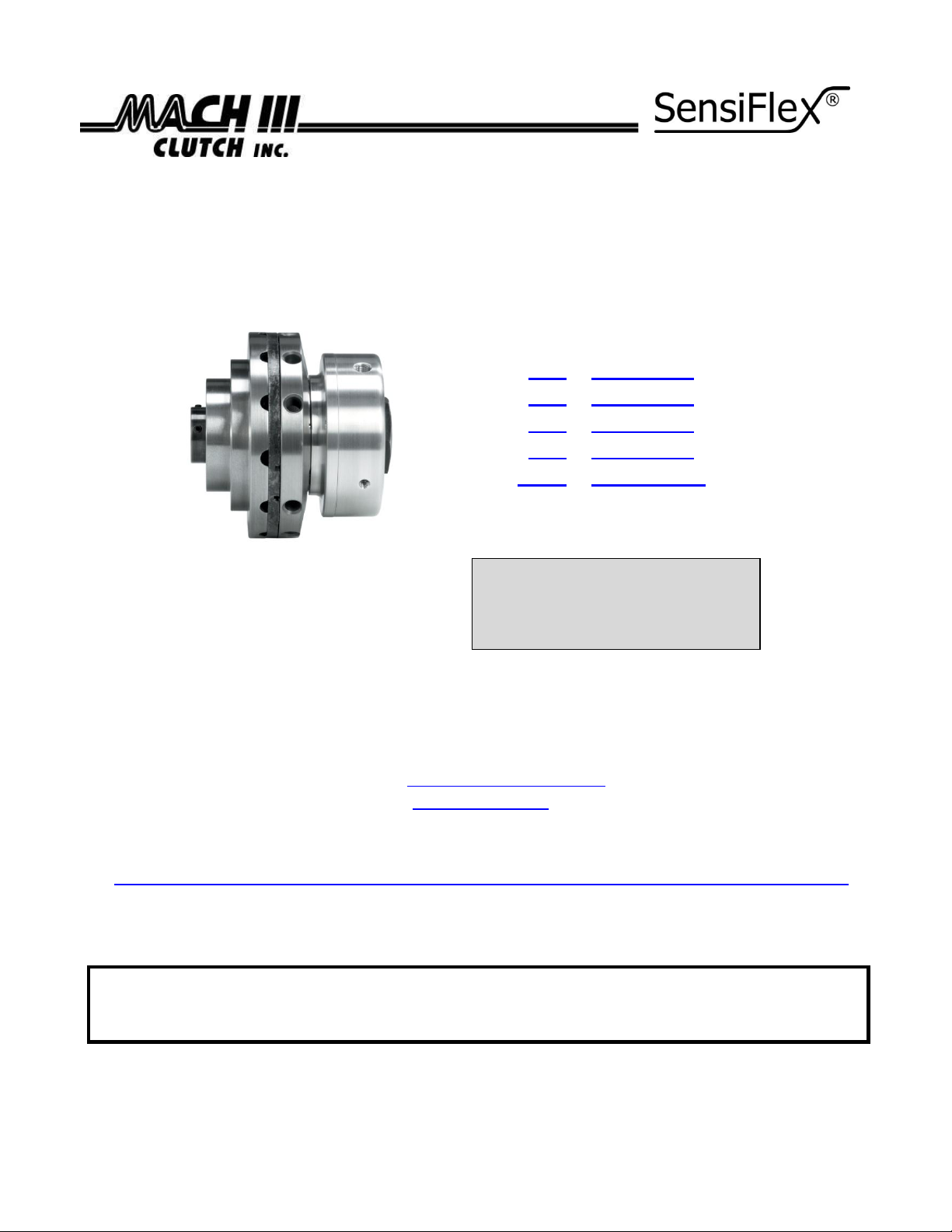
SENSIFLEX® SHAFT INPUT TENSION CONTROL CLUTCH
Patent No. 6,578,691 B1
Catalog Products:
38SI & 38SI-ULOW
58SI & 58SI-ULOW
78SI & 78SI-ULOW
98SI & 98SI-ULOW
118SI & 118SI-ULOW
And non-catalog variations
of this clutch design.
Mach III Technical Support
Toll Free: 866-291-0849
International: 01-859-291-0849
Email: engineering@machiii.com
www.machiii.com
Spec sheets and 3D models are available on the Mach III website:
http://www.machiii.com/Products/Tension-Control/Pneumatic-Clutch/SensiFlex-Shaft-Input-Clutches.asp
Please contact Mach III to obtain assembly and parts list drawings.
This product includes rotating equipment and should be guarded according to OSHA
requirements and other Federal, State and local regulations.
It is the responsibility of the user to provide necessary guarding.
© Mach III Clutch, Inc. All Rights Reserved
CLICK on product numbers above
to obtain the product detail sheet
which includes dimensional data
helpful during installation.
7/10/2013 CLUTCH_SENSIFLEX_SI_MANUAL Page 1 of 5
Page 2
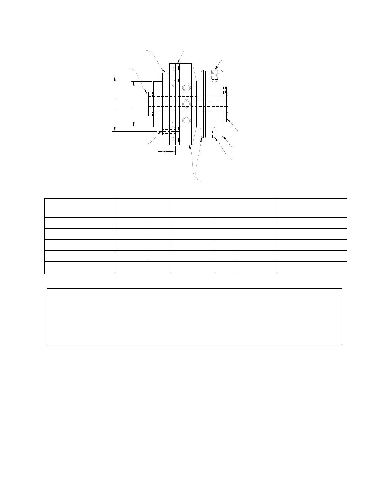
X
DRIVE HUB
INPUT MEMBER
FRICTION LINING
AIR INLET
RETAINER NUT
AIR CYLINDER
INPUT FOR REACTION ARM
E
PISTON - DRIVE DISC
ASSEMBLY
SLEEVE
OUTPUT MEMBER
H
BC
Reference Diagram:
Product#
H E X
BC
Air Inlet
Reaction Arm Input
38SI/38SI-ULOW
1.875
0.61
(3) 10 - 24
2.25
1/16" NPT
10 - 24
58SI/58SI-ULOW
2.749
0.87
(3) 1/4 - 20
3.25
1/8" NPT
1/4 - 20
78SI/78SI-ULOW
3.875
1.20
(3) 5/16 - 18
4.50
1/8" NPT
1/4 - 20
98SI/98SI-ULOW
5.000
1.25
(6) 3/8 - 16
5.63
1/8" NPT
1/4 - 20
118SI/118SI-ULOW
6.250
1.50
(6) 7/16 - 14
7.00
1/4" NPT
5/16 - 18
**IMPORTANT**
The gap between the friction and drive surface is factory set between 0.010 and 0.020 Inch.
This is the ideal clearance for proper performance.
Increasing this gap may result in air leaks and damage to the diaphragm actuator.
Decreasing this gap prevents full disengagement of the brake.
I. Installation
A. SHAFT PREPARATION & MOUNTING
7/10/2013 CLUTCH_SENSIFLEX_SI_MANUAL Page 2 of 5
Mach III Clutch products are bored to fit a precision plug gauge for the specified bore size
and should slide-fit your shaft. Make certain that the shaft is free of burrs or nicks. It
may be necessary to file or sand the shaft to assure a slide fit. Never hammer the clutch
onto the shaft. Hammering on the clutch may cause evident damage or subtle injury that
will shorten the wear life of the unit, and will void the warranty. Apply the anti-seize (E-Z
Break®) lubricant from the packet provided, or equivalent, to the shaft. Slide the clutch
over the key on the shaft, align the pulley or sprocket and tighten the set screws.
Page 3

B. AIR LINE CONNECTION
Product
Original Thickness
of Friction Disc
Replace When Worn To A
Thickness Of:
38SI/38SI-ULOW
3/16 Inch
9/64 Inch
58SI/58SI-ULOW
1/4 Inch
1/8 Inch
78SI/78SI-ULOW
5/16 Inch
3/16 Inch
98SI/98SI-ULOW
7/16 Inch
5/16 Inch
118SI/118SI-ULOW
7/16 Inch
5/16 Inch
Air supply should be both filtered and regulated. Contamination in the air supply will
cause damage to the clutch, particularly to the diaphragm actuator. Connect a flexible
airline to the air inlet using a thread sealing compound. Do not use rigid piping.
C. ANTI-ROTATION (REACTION) ARM CONNECTION
Install a reaction arm (bolt, rod, or other device) into hole provided. This is necessary
to prevent rotation of the air cylinder (due to the drag in the bearings) and to keep
pressure off of the air inlet. This arm should not be held rigidly.
Please refer to Mach III’s Anti-Rotation (Reaction) Arm Installation Instructions
document for illustrations of proper mounting. This document is available from the
Mach III website: http://www.machiii.com/pdf/ReactionArmInstallation.pdf or by
calling Mach III to have a copy sent by email or fax.
D. FINAL INSPECTION & TESTING
Check alignment of the sprocket or pulley. Cycle the clutch with the machine off to
check for air leaks and to ensure proper engagement and release. After a short run,
check set screws and alignment.
II. Operation:
The SensiFlex® clutch is designed for use in slip applications, typically to maintain tension on a
web during rewinding or a similar tension control application.
III. Routine Maintenance:
Friction linings (discs) are a “wear” item and in a constant slip application, periodic
replacement of the friction disc will be necessary. The frequency of disc replacement varies
with each application. Screws are used to mount the friction disc on the drive disc. Wear of
the friction disc should be monitored so that it can be replaced prior to the point at which the
heads of the mounting screws would make contact with the input sleeve. See chart below for
replacement point recommendations. Mach III Clutch, Inc. should always be consulted to assist
with selection of a SensiFlex® Clutch to assure that required tension can be maintained while
dissipating the heat caused by constant slip.
Friction Disc Replacement Recommendations
7/10/2013 CLUTCH_SENSIFLEX_SI_MANUAL Page 3 of 5
Page 4

Repair Parts & Services
Kits Available
Contents
Part Numbers
Facing Kit
Friction Disc & Mounting Screws
38SI-FCGK, 38SI-ULOW-FCGK,
58SI-FCGK, Etc. . . .
Repair Kit
Friction Disc, Mounting Screws, Spring(s),
Diaphragm
38SI-RPRK, 38SI-ULOW-RPRK,
58SI-RPRK, Etc. . . .
Tools Needed
Hex wrench set
Retainer (snap) ring pliers
Flat head screw driver
Scraper (if replacing bearings)
0.010 Inch feeler gauge
Compounds Required
Grease
O-Ring lubricant
Anti-Seize Lubricant
For part numbers of components not included in the kits above, please contact Mach III Clutch,
Inc. or your distributor. Factory repair is also available. A return materials authorization (RMA)
number must be obtained prior to sending any unit in for repair. Mach III Clutch is not
responsible for products returned without authorization.
IV. Repair Procedure
A. DISASSEMBLY
Loosen set screws using appropriate hex wrench and slide the clutch off of the shaft. Place the
clutch on a work surface with the air cylinder end of the clutch upward. Loosen the set screw
in the retainer nut and remove nut using a wrench or channel lock pliers. The air cylinder
bearing is a slide fit on the drive hub. The cylinder, piston and cone assembly should come off
of the drive hub together. You may need to strike the hub, or on an object inserted into the
hub with a rubber mallet or similar soft face hammer, while pulling the cylinder upwards to
remove.
B. DRIVE SURFACE INSPECTION & FRICTION DISC REPLACEMENT
Inspect the drive surface of the cast iron sleeve input member. Grooves in the surface would
indicate that the friction disc should have been replaced sooner and the heads of the mounting
screws have made contact. This surface must be free from grooves, burrs and foreign materials
in order for the clutch to operate properly. If damage is pronounced, please contact Mach III
Clutch or your distributor about replacing the sleeve and procedure. In addition, clutch should
be inspected for discoloration (turning blue). If discoloration is present, the unit is being
operated beyond its capacity and Mach III Clutch should be contacted for assistance. To
replace the friction disc, remove brass screws and friction disc, make sure mounting surface is
smooth and free from contamination. Mount new friction disc by snugging all screws first then
tighten firmly using an alternating sequence. Do not over-tighten.
C. INSPECTION OF BEARINGS
Check bearings for external damage (missing seals, etc.). Make sure the bearings rotate freely
and smoothly by hand. If bearing replacement is necessary, consult Mach III or your distributor
7/10/2013 CLUTCH_SENSIFLEX_SI_MANUAL Page 4 of 5
for the bearing sizes and replacement procedures.
Page 5

D. DIAPHRAGM INSPECTION & REPLACEMENT
Diaphragm replacement should rarely be necessary if the air supply is regulated and free of
contamination and if the gap between the friction and drive disc is properly set.
Separate the air cylinder and piston by pulling apart taking care not to bend pins. Pinch the
diaphragm and pull from the grooves which retain it. Make sure that the retaining grooves and
surface underneath the diaphragm are clean & free from debris. Lubricate the new diaphragm
(if replacement is necessary) with an O-ring lubricant such as Dow Corning® #4. Install with the
lips located on the ID and OD of the diaphragm facing downward. Press the lips into the
grooves by applying pressure while gliding a finger along each perimeter of the diaphragm.
Assure that the lips are fully seated by running your thumb across the surface of the diaphragm
in a clockwise motion several times.
E. REASSEMBLY
1. Apply a thin coat of grease (such as Molykote® G-N Metal Assembly Paste) to the hex
drive surface of the drive hub. Be sure the spring is in place over drive hub and
surrounding the hex portion of the hub. Place piston/drive disc assembly over drive
hub. Drive disc assembly should move freely over hex.
2. Place cylinder assembly over hub. Align pins in the holes in the piston and manually
press the cylinder downward to reconnect with piston. The cylinder assembly will not
fully seat until the retaining nut is tightened.
3. Place the adjustment nut on the threads and tighten to a point where a 0.010 - 0.020
gap remains between friction lining and sleeve input member. It is recommended that a
0.010 feeler gauge be used. Sleeve output member should turn freely after reassembly.
If you can feel contact between the friction and drive surface when rotating, loosen
adjustment nut just enough to provide clearance. Tighten set screw in adjustment nut
snuggly when proper clearance has been achieved.
4. See “Installation” section on Page 2 of these instructions for the proper procedure for
re-installing the clutch.
Technical assistance is available by contacting Mach III Clutch, Inc.
Mach III Product Warranty
http://www.machiii.com/Resources/Warranty-Info.asp
Mach III Clutch, Inc.
101 Cummings Drive ● Walton, KY 41094
Toll free 866.291.0849 ● International 859.291.0849 ● Fax 859.655.8362
info@machiii.com ● engineering@machiii.com ● www.machiii.com
7/10/2013 CLUTCH_SENSIFLEX_SI_MANUAL Page 5 of 5
 Loading...