

Page 1

Simplifying IoT from edge to enterprise
MACH-3
Installation and
Conguration Manual
January 31, 2019
Revision 5.0
Page 2

Notes, cautions, and warnings
MACH-3 Installation and Conguration Manual
Notes, cautions, and warnings
NOTE: A NOTE indicates important information that helps you make better use of your product.
CAUTION: A CAUTION indicates either potential damage to hardware or loss of data and tells you
how to avoid the problem.
WARNING: A WARNING indicates a potential for property damage, personal injury, or death.
!
Copyright 2018 Machfu Inc. All rights reserved. Machfu and other trademarks are trademarks of Machfu Inc.
Other trademarks may be trademarks of their respective owners.
i
Page 3

MACH-3 Installation and Conguration Manual
Table of Contents
Table of Contents
1 Overview ....................................................................................................2
1.1 SYSTEM VIEWS ..................................................................................................................................................2
1.1.1 Front Panel View ..........................................................................................................................................2
1.1.2 Right Side SIM Door View ...........................................................................................................................3
1.1.3 Bottom View .................................................................................................................................................3
2 Installing your MACH-3 Gateway ............................................................. 4
2.1 PROFESSIONAL INSTALLATION INSTRUCTIONS ..........................................................................................5
2.1.1 Installation Personnel.................................................................................................................................5
2.1. 2 Installation Location ...................................................................................................................................5
2.1. 3 External Antenna.........................................................................................................................................5
2.2 GATEWAY MOUNTING OPTIONS ....................................................................................................................5
2.3 SETTING UP MACH-3 GATEWAY .....................................................................................................................6
3 Gateway Conguration .............................................................................8
3.1 OVERVIEW ..........................................................................................................................................................8
3.1.1 System Requirements ................................................................................................................................8
3.1. 2 Log in .............................................................................................................................................................8
3.1. 3 Navigation ....................................................................................................................................................8
3.2 DASHBOARD ................................................................................................................................................9
3.2.1 General Information ........................................................................................................................................9
3.2.2 GPS ..............................................................................................................................................................10
3.2.3 Cellular Information .................................................................................................................................. 10
3.2.4 VPN .............................................................................................................................................................. 11
3.2.5 Ethernet 1 ...................................................................................................................................................11
3.2.6 Ethernet 2 ................................................................................................................................................... 11
3.2.7 Wi-Fi Client .................................................................................................................................................12
3.2.8 Wi-Fi Access Point......................................................................................................................................13
Simplifying IoT from edge to enterprise
ii
Page 4

Table of Contents
3.3 WIRELESS INTERFACES ..................................................................................................................................14
3.3.1 Wi-Fi Client .................................................................................................................................................15
3.3.2 Wi-Fi Access Point......................................................................................................................................15
3.3.3 Cellular ........................................................................................................................................................16
3.4 WIRED INTERFACES ........................................................................................................... .............................17
3.4.1 Ethernet ......................................................................................................................................................17
3.4.2 Serial ............................................................................................................................................................18
3.5 NETWORK ........................................................................................................................................................19
3.5.1 Bridge ...................................................... ................................................................................................... 20
3.5.2 VPN ............................................................................................................................................................. 20
3.5.3 Open VPN .................................................................................................................................................. 22
MACH-3 Installation and Conguration Manual
3.5.4 Port Forwarding ....................................................................................................................................... 22
3.5.5 Source Network Address Translation .................................................................................................... 24
3.5.6 Routes ........................................................................................................................................................ 25
3.6 SETTINGS ........................................................................................................................................................ 26
3.6.1 Prole ......................................................................................................................................................... 26
3.6.2 Users & Roles ............................................................................................................................................ 26
3.6.3 Reset User’s Password ............................................................................................................................ 28
3.7 SYSTEM ........................................................................................................................................................... 29
3.7.1 System Upgrade ....................................................................................................................................... 30
3.7.2 General Settings ....................................................................................................................................... 30
3.7.3 Applications............................................................................................................................................... 32
3.7.4 Start /Stop App .......................................................................................................................................... 33
4 Regulatory Notices ..................................................................... .............35
5 Appendix ..................................................................................................37
5.1 Cellular Bands ................................................................................................................................................ 37
5.2 Antenna Specication ................................................................................................................................... 37
5.3 Contacting Machfu ........................................................................................................................................ 38
iii
Page 5

MACH-3 Installation and Conguration Manual
Revision History
Revision History
Revision Description Date
1.0 Initial release 1/4/2017
2.0 Revision 1/5/2018
3.0 Revision 8/1/2018
4.0 Revision 10/3/2018
5.0 Revision 1/31/2019
Simplifying IoT from edge to enterprise
1
Page 6
1 Overview
1. Overview
MACH-3 Installation and Conguration Manual
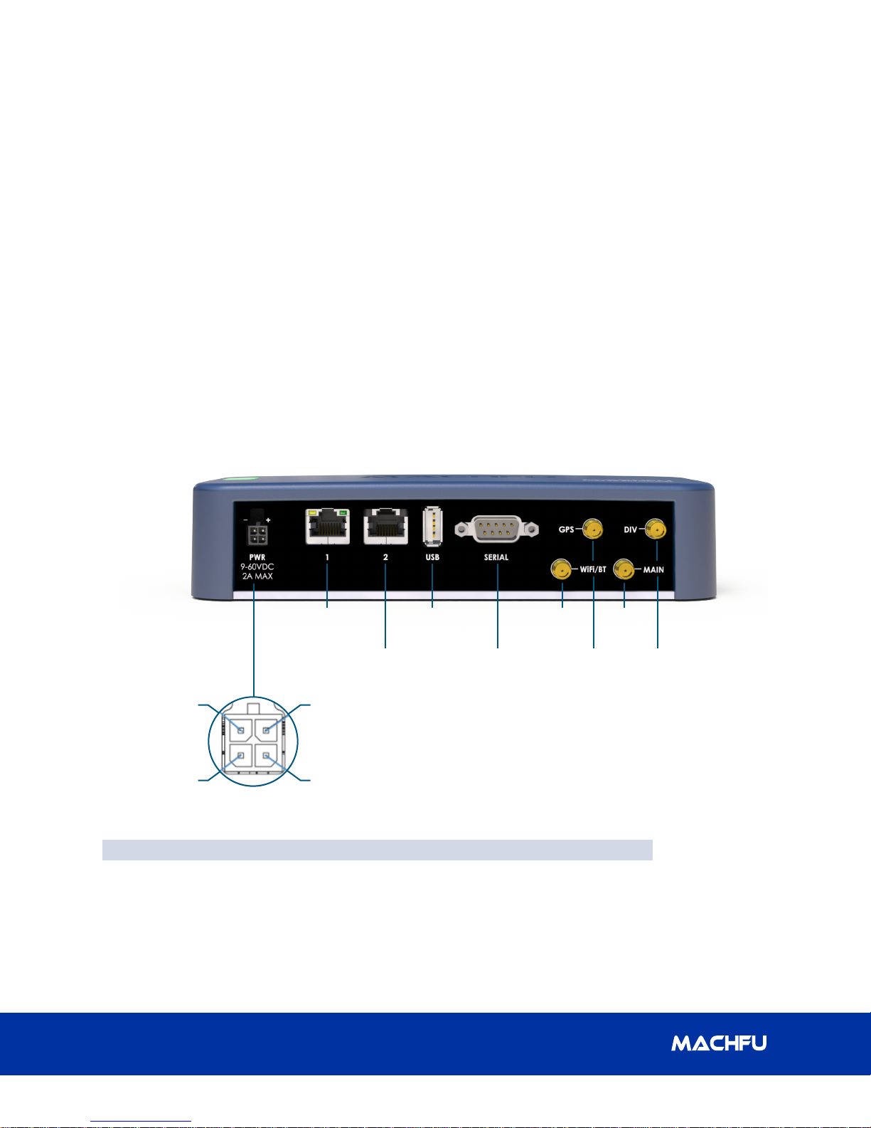
The MACH-3 Gateway is an Industrial Internetof-Things (IIoT) device. It is deployed on
the MACH-3 Edge network, enabling you to
securely collect, analyze, and act on data from
multiple devices and sensors. It enables you
to connect with industrial devices used in the
1.1 System Views
1.1.1 Front Panel View
electric grid, oil & gas, manufacturing, and
other applications. The MACH-3 Gateway has
a low-power architecture, which is capable of
supporting industrial automation workloads
while remaining fan-less for environmental
and reliability requirements.
GND
Switch in(+)
Ethernet 1
Ethernet 2
Power
(9-60 VDC)
Switch in(-)
(Type A)
RS-232
(DTE)
Features
1 Power Connector 6 Wi-Fi / BT
2 Ethernet 1 7 GPS
3 Ethernet 2 8 Cellular (Main)
4 USB 9 Cellular (Diversity)
5 RS-232
Wifi/BTUSB
Cellular
(Main)
DIVGPS
2
Page 7
MACH-3 Installation and Conguration Manual
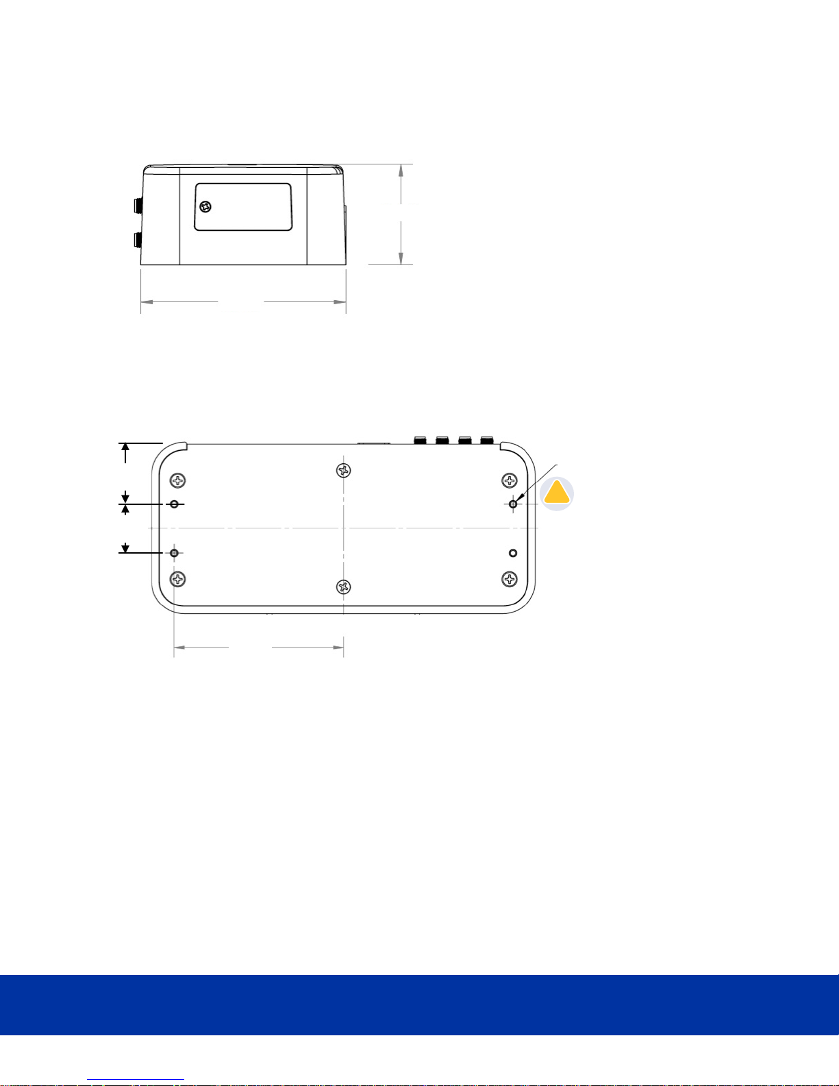
1.22”
0.97”
Maximum length 1.25”
6-32 mounting screw (x4)
3.35”
!
1.1.2 Right Side SIM Door View
3.39”
1.1.3 Bottom View
1 Overview
1.66”
Simplifying IoT from edge to enterprise
3
Page 8

2 Installing your MACH-3 Gateway
!
MACH-3 Installation and Conguration Manual
2. Installing your MACH-3 Gateway
WARNING: Before you begin any of the
!
procedures in this section, read the safety
and regulatory information that is shipped
with your system. For additional best practices
information, go to www.machfu.com/
regulatory_compliance.
WARNING: The MACH-3 Gateway must
!
be installed by knowledgeable and skilled
personnel familiar with local and/or
international electrical statutes and regulations.
WARNING: The MACH-3 Gateway is not
!
designed for use in wet environments. If the
MACH-3 Gateway is to be installed in a wet
environment, depending on the location and
environment, it must be installed in a panel
box or enclosure with an Ingress Protection (IP)
rating of IP54, IP65, or higher.
WARNING: To reduce the risk of electric shock,
!
power to the DC+ and DC- terminals must be
provided by a power supply or transformer/
rectier circuit that is designed with double-
insulation. The power supply or power circuit
source must comply with local codes and
regulations; for example, in the USA, NEC Class
2 (SELV/limited energy circuit, or LPS circuitry). If
powered by a battery, double-insulation is not
required.
the lack of ventilation inside an enclosure
can cause the operating temperature
of the MACH-3 Gateway to be greater
than the outside ambient temperature.
Continuous operation of the MACH-3
Gateway at temperatures greater than
80°C(176°F) may result in an increased
failure rate and a reduction of the product
life. Ensure that the maximum operating
temperature of the MACH-3Gateway when
placed inside an enclosure is 80°C (176 °F)
or less.
WARNING: The symbol indicates hot surface
!
or adjacent hot surface that can cause a burn.
Allow equipment to cool or use protective gloves
when handling to reduce risk of a burn.
WARNING: Always ensure that the available
!
power source matches the required input power
of the MACH-3 Gateway. Check the input power
markings next to power connector(s) before
making connections. The 9-60 VDC power
source must be compliant with local Electrical
Codes and Regulations.
WARNING: To ensure the protection provided
!
by the MACH-3 Gateway is not impaired, do not
use or install the system in any manner other
than what is specied in this manual.
WARNING: Ensure that the power source
!
providing power to the MACH-3 Gateway is
reliably grounded and ltered such that the
peak-to-peak ripple component is less than 10
percent of the input DC voltage.
WARNING: When installing the MACH-3
!
Gateway, use a cable appropriate for the
load currents: 3-core cable rated 5 A at
90°C (194°F) minimum, which conform to
either IEC 60227 or IEC 60245. The system
accepts cables from 0.8 mm to 2 mm. The
maximum operating temperature of the
MACH-3 Gateway is 80°C (176 °F). Do not
exceed this maximum temperature while
operating the MACH-3 Gateway inside an
enclosure. Internal heating of the MACH-3
Gateway electronics, other electronics, and
4
WARNING: If a battery is included as part of the
!
system or network, the battery must be installed
within an appropriate enclosure in accordance
with local re and electrical codes and laws.
WARNING: The system is for installation
!
in a suitable industrial enclosure with toolremovable cover or door only.
WARNING: The system is for installation in
!
Class I, Division 2, Groups A, B, C, D hazardous
locations or non-hazardous locations only.
WARNING: EXPLOSION HAZARD: DO NOT
!
CONNECT OR DISCONNECT EQUIPMENT
WHEN ENERGIZED. Perform connections or
disconnections to equipment only when not
energized or the area is known to be nonhazardous.
Page 9

MACH-3 Installation and Conguration Manual
1.22 ”
0.97”
Maximum length 1.25”
6-32 mounting screw (x4)
3.35”
!
2 Installing your MACH-3 Gateway
2.1 Professional
Installation Instructions
2.1.1 Installation Personnel
This product is designed for specic
applications and needs to be installed by
qualied personnel with RF and regulatory-
related knowledge. The general user shall not
attempt to install or change the settings.
2.1.2 Installation Location
The product shall be installed at a location
where the radiating antenna is kept 20 cm
from nearby people in its normal operation
condition in order to meet regulatory RF
exposure requirements.
2.2.2 Din-Rail Mount
Note: MACH-3 Din-Rail mounting
option sold separately
2.2.3 Mounting Plate
Note: MACH-3 Mounting Plate option
sold separately
2.2.3.1 Mounting Instructions
1. Remove the two center screws from
the base plate of the Machfu gateway.
(marked with a red circle in the picture
below.)
2.1.3 External Antenna
Use only approved antennae. Non-approved
antennae may produce spurious or excessive
RF transmitting power which may lead to a
violation of FCC/IC limits.
2.2 Gateway Mounting
Options
2.2.1 Bottom Mount
2. Align the mounting plate’s counter
screw holes with the center screw
holes on the base plate of the gateway
and screw them together as indicated
in the picture below.
3. Mount the gateway into your unit using
the exposed screw holes available on
the mounting plate.
Simplifying IoT from edge to enterprise
5
Page 10
2 Installing your MACH-3 Gateway
2.3 Setting up MACH-3 Gateway
MACH-3 Installation and Conguration Manual
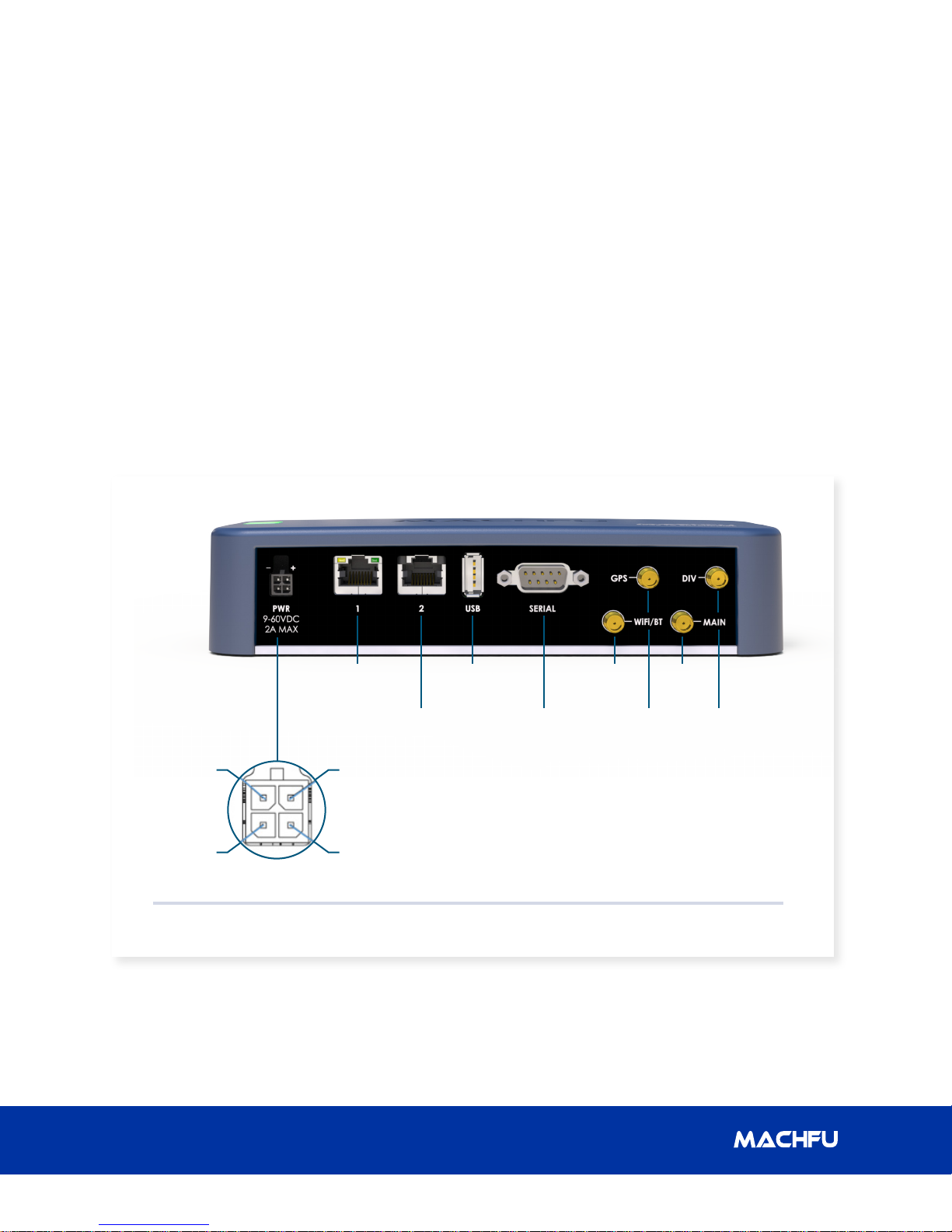
1. Connect an Ethernet RJ45 cable to
Ethernet 1 as shown in Figure 1: Front
Panel View.
2. Connect antennae as shown in Figure
1: Front Panel View using antennae
that meet the minimum conguration
specied in the Appendix on page 37.
3. Open the micro-SIM/micro-SD card
access door and insert the micro-SIM
card in the SIM-Card slot as shown in
Figure 2: SIM Card Installation before
turning on the MACH-3 gateway.
4. The gateway power connector is a
Molex Microt 3.0 four pin connector
wired as shown in Figure 3. The four
pin connector accepts a 9 - 60 VDC
power supply input and a contact
closure input.
Pin 1: Contact Input common
Pin: 2 Contact Input
Pin: 3 Power (9- 60 VDC)
Pin: 4 Ground
GND
Switch in(+)
Figure 1: Front Panel View
Ethernet 1
Power
(9-60 VDC)
Switch in(-)
Ethernet 2
(Type A)
RS-232
(DTE)
Wifi/BTUSB
Cellular
(Main)
DIVGPS
6
Page 11

MACH-3 Installation and Conguration Manual
Unscr ew and remove t he SIM door. Replace and sc rew in t he SIM do or.Slide SIM card into ho lder throug h
openi ng and push unt il latc h clicks.
To remove push again until latch
disengages, and slide SIM card out.
Figure 2: SIM Card Installation
GND
Switch in(+)
Figure 3: Power connector pinout
Power
(9-60 VDC)
Switch in(-)
Simplifying IoT from edge to enterprise
7
Page 12
3 Gateway Conguration
3. Gateway Conguration
MACH-3 Installation and Conguration Manual
3.1 Overview
The MACH Gateway Conguration Tool is used
to congure MACH-3 Gateway products. This
User Guide describes how the tool can be
used to congure and set various parameters
in the gateway for optimizing your Industrial
Internet-of-Things Network and Application.
3.1.1 System Requirements
● Microsoft Windows 7, Windows 8;
● Linux; or
● Mac OS X
● Web Browser:
● Mozilla Firefox, Apple Safari,
Google Chrome, or Microsoft
Internet Explorer 11 (or above)
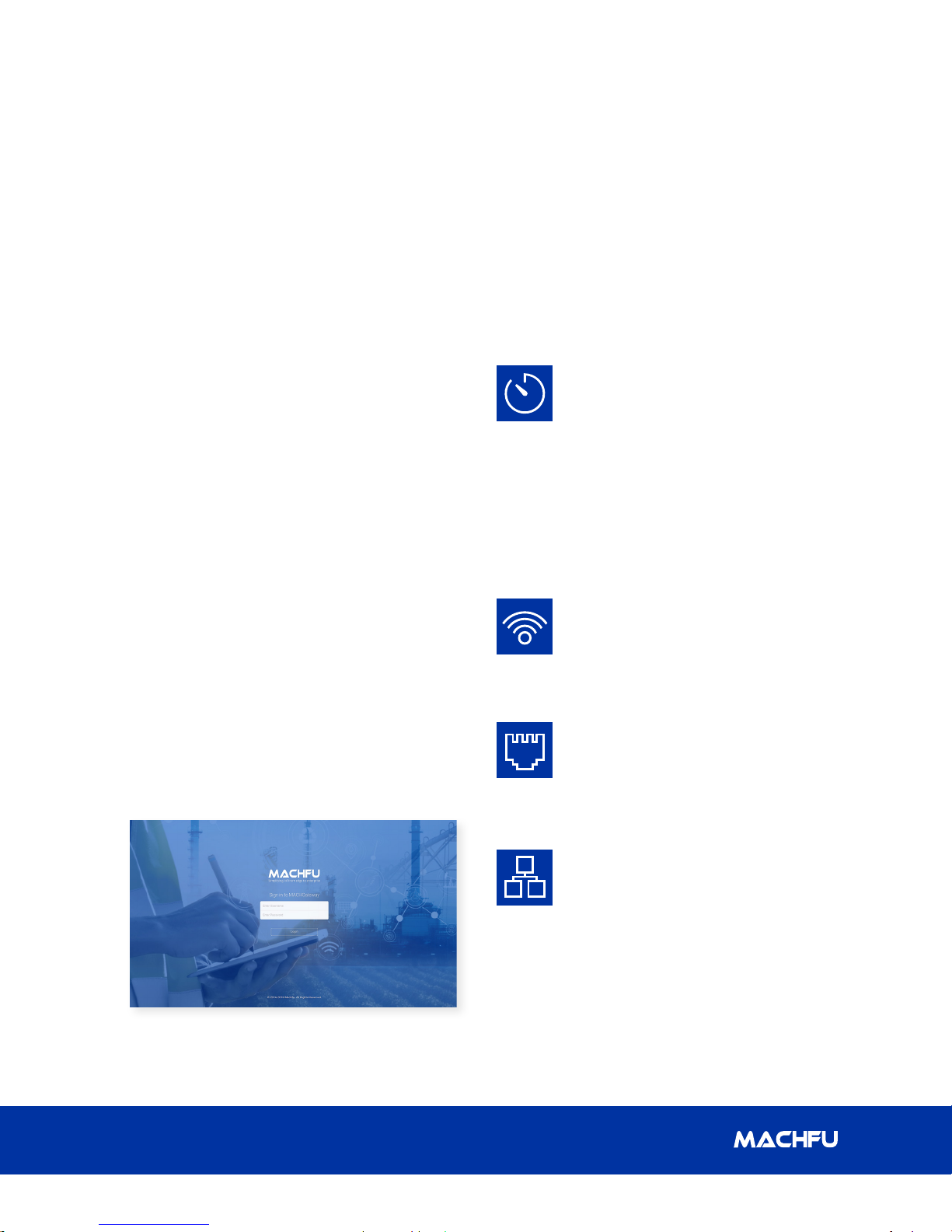
3.1.2 Log in
To access the MACH Gateway Conguration
Interface, perform the following steps:
1. Launch your web browser.
2. Enter hps://192.168.1.1:8443 in the
address eld.
3. Press Enter (PC) or Return (Mac).
3.1.3 Navigation
The Mach Gateway Conguration Interface
contains six main tabs, seen in the navigation
bar on the left side of the interface. Each tab
may contain multiple sections and each web-
based management page is used to congure
a specic aspect of the Gateway.
DASHBOARD is a synopsis of all the
network conguration, and state
elements of the Gateway. It displays
device information such as name
and serial number, and the current
state of physical and virtual network
interfaces. In addition, it displays
the GPS information of the device.
Page 9 provides details on the
DASHBOARD conguration page.
WIRELESS congures operating
mode of the cellular and the
two Wi-Fi interfaces. Page 14
provides details on the WIRELESS
conguration pages.
WIRED congures the operating
mode of the two Ethernet interfaces;
and the Serial Terminal settings.
Page 17 provides details on the
WIRED conguration pages.
The Login screen appears as below.
Enter the Username and Password elds
and click the ‘Login’ button.
8
NETWORK congures system
management services: Ping
Watchdog, Simple Network
Management Protocol (SNMP),
servers (web, SSH, Telnet), Network
Time Protocol (NTP) client, Dynamic
Domain Name System (DDNS) client,
system log, and device discovery.
Page 21 provides details on the
NETWORK conguration pages.
Page 13

MACH-3 Installation and Conguration Manual
3 Gateway Conguration
SETTINGS handles the user and
password management of the MACH
Gateway. Page 26 provides details on
the SETTINGS conguration pages.
SYSTEM handles system
upgrade, device reboot, remote
support setting and applications
management. Page 29 provides
details on the SYSTEM conguration
pages.
3.2 Dashboard
DASHBOARD is a synopsis of all the network conguration, and state elements of the Gateway. It
provides a high-level view of the device and network interfaces as well as the GPS information.
3.2.1 General Information
• Device name – Classication of the MACH Gateway.
• Device SKU – Stock Keeping unit of the Gateway.
• Serial number – Unique serial number of the Gateway. Filled by the Gateway.
• Release – Current version number of system image.
• Security Patch – Date of the last security patch update.
• Build Date – Date of the last system build.
• Uptime – Time elapsed since the last boot-up. It is shown in days, hours, minutes and seconds.
• Load – CPU usage of the Gateway.
• Memory – Memory currently used in the Gateway.
• Disk/Storage – Storage available for Applications in the Gateway.
Simplifying IoT from edge to enterprise
9
Page 14

3 Gateway Conguration
MACH-3 Installation and Conguration Manual
3.2.2 GPS
• Location – Latitude/Longitude of the Gateway.
• Altitude – Altitude of the Gateway.
• GPS Time – UTC time as received by GPS.
• Satellites (In Use) – Number of GPS satellites in use by the Gateway.
• Accuracy – GPS readings accuracy.
• GPS Fix Time – Last x from the GPS satellites.
3.2.3 Cellular Information
• Status – Indicates if the Cellular link is Enabled or Disabled.
• PPP UP/DOWN – Indicates if the Cellular link is UP or DOWN.
• IP Address – IP address of the PPP link.
• Network Type – Type of Cellular network.
• Signal Strength – Signal strength of the cellular link in dBm.
• Tx Bytes – Number of bytes transmitted since boot-up.
• Rx Bytes – Number of bytes received since boot-up.
10
Page 15

MACH-3 Installation and Conguration Manual
3.2.4 VPN
• Type – Type of VPN connection.
• IP Address – IP address of VPN connection.
• VPN UP/DOWN – Indicates if VPN connection is UP or DOWN.
• VPN Server – IP address of VPN server.
3.2.5 Ethernet 1
3 Gateway Conguration
• Status – Indicates if the Ethernet connection is Enabled or Disabled.
• Link UP/DOWN – Indicates if the Ethernet link is UP or DOWN.
• Link Speed – Data rate on the Ethernet 1 (eth0) Interface.
• MAC Address – MAC address of the Ethernet link.
• IP Address – IP address of the Ethernet link.
• Netmask – Subnet denition.
• Mode – Indicates if the connection mode is STATIC, DHCP Client or Bridge.
• Tx Bytes – Number of bytes transmitted since boot-up.
• Rx Bytes – Number of bytes received since boot-up.
Simplifying IoT from edge to enterprise
11
Page 16

MACH-3 Installation and Conguration Manual3 Gateway Conguration
3.2.6 Ethernet 2
• Status – Indicates if the Ethernet connection is Enabled or Disabled.
• Link UP/DOWN – Indicates if the Ethernet link is UP or DOWN.
• Link Speed – Data rate on the Ethernet 2 (eth1) Interface.
• MAC Address – MAC address of the Ethernet link.
• IP Address – IP address of the Ethernet link.
• Netmask – Subnet denition.
• Mode – Indicates if the Ethernet is acting as STATIC IP, DHCP Server or Bridge.
• Tx Bytes – Number of bytes transmitted since boot-up.
• Rx Bytes – Number of bytes received since boot-up.
3.2.7 Wi-Fi Client
• Status – Indicates if the Wi-Fi client or station is Enabled or Disabled.
• SSID – Species the wireless network name or SSID (Service Set Identier) used to identify the
WLAN.
• Link UP/DOWN – Indicates if the Wi-Fi link is UP or DOWN.
• MAC Address – MAC address of the Wi-Fi link.
• IP Address – The IP address of the Wi-Fi link.
• Gateway – IP Address of the Gateway.
• Netmask – Subnet denition.
• Tx Bytes – Number of bytes transmitted since boot-up.
• Rx Bytes – Number of bytes received since boot-up.
12
Page 17

MACH-3 Installation and Conguration Manual
3 Gateway Conguration
3.2.8 Wi-Fi Access Point
• Status – Indicates if the Wi-Fi Access Point is Enabled or Disabled.
• SSID – Species the wireless network name or SSID (Service Set Identier) used to identify the
WLAN.
• Link UP/DOWN – Indicates if the Wi-Fi link is UP or DOWN.
• MAC Address – MAC Address of the Wi-Fi Access Point.
• IP Address – IP Address of the Wi-Fi Access Point.
• Netmask – Subnet denition.
• Mode – Indicates if the AP is acting as DHCP Server or Bridge.
• Tx Bytes – Number of bytes transmitted since boot-up.
• Rx Bytes – Number of bytes received since boot-up.
Simplifying IoT from edge to enterprise
13
Page 18

3 Gateway Conguration
MACH-3 Installation and Conguration Manual
3.3 Wireless Interfaces
The wireless interface congurations are used to congure the Wi-Fi and Cellular radios on the
MACH Gateway.
3.3.1 Wi-Fi Client
In the Client mode, the following congurations are seen
• Set the ‘Enable’ button to use the Wi-Fi in the Client mode.
• SSID – Specify the wireless network name or SSID (Service Set Identier) used to identify the
WLAN.
• Enter the WPA2 Passphrase.
14
Page 19
MACH-3 Installation and Conguration Manual
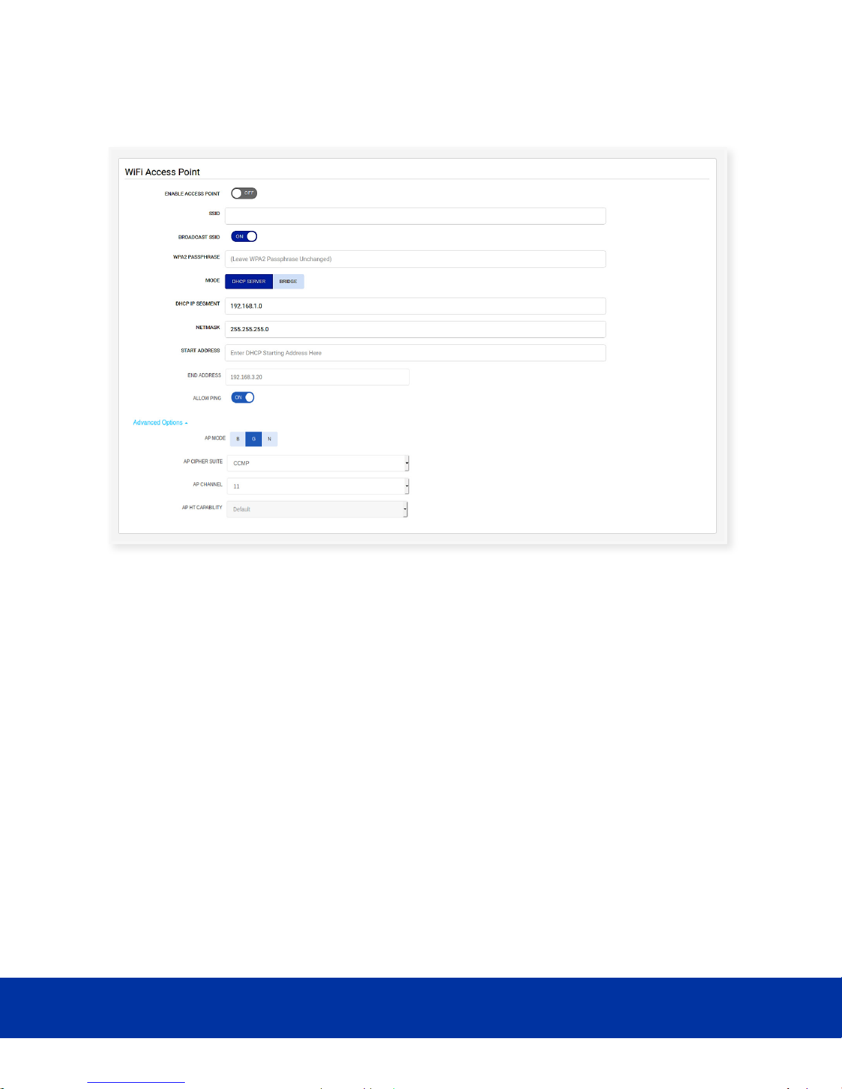
3.3.2 Wi-Fi Access Point
3 Gateway Conguration
In the Access Point mode, the following conguration panel is seen.
• Set the ‘Enable’ button to use the Wi-Fi in the access point mode
• SSID – Specify the wireless network name or SSID (Service Set Identier) used to identify
the WLAN
• Set the ‘Broadcast SSID’ button if you want the SSID to be visible
• Enter the WPA2 passphrase
• Set the ‘Mode’ to DHCP SERVER or BRIDGE
• Enter IP address
• Enter Netmask value
• Enter the DHCP range of values
• Set ‘Allow Ping’ if you want the AP to be ping-enabled
Simplifying IoT from edge to enterprise
15
Page 20
MACH-3 Installation and Conguration Manual3 Gateway Conguration
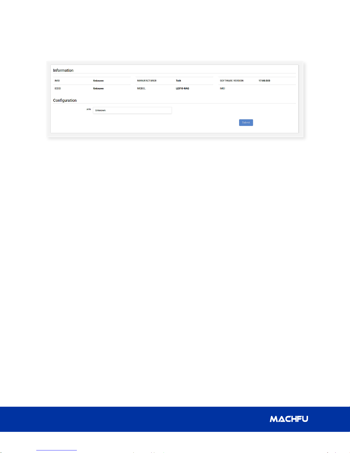
3.3.3 Cellular
In the Cellular section, the following information is seen.
• IMSI – The International Mobile Subscriber Identity (IMSI) identies the user of the cellular
network.
• ICCID – The Integrated Circuit Card Identier (ICCID) is a 19-digit identication number for
SIM.
• Manufacturer – The manufacturer of cellular modem in the MACH Gateway.
• Model – The model of cellular modem in the MACH Gateway.
• Software Version – The version number of the cellular modem software.
• IMEI – The International Mobile Equipment Identity (IMEI).
The following conguration can be seen
• Set the ‘APN’ of the cellular SIM.
• Set cellular ‘Operator’ (for select models).
16
Page 21

MACH-3 Installation and Conguration Manual
3 Gateway Conguration
3.4 Wired Interfaces
The MACH Gateway has two wired interfaces: Ethernet and Serial. However, the Ethernet has two
ports: Ethernet 1 (eth0) and Ethernet 2 (eth1). To congure Ethernet or Serial interface, click the
WIRED Tab on the left panel.
3.4.1 Ethernet
The two Ethernet ports have identical conguration elements. The help guide applies to both ports.
You have the option of enabling or disabling an Ethernet interface even if the interface is physically
connected. To Enable, set Enable Ethernet switch to ‘ON’ and to disable, set it to ‘OFF’.
Simplifying IoT from edge to enterprise
17
Page 22

MACH-3 Installation and Conguration Manual3 Gateway Conguration
3.4.1.1 IP Addressing
If the Gateway has a static IP address,
select ‘STATIC IP’ and enter the address in
the IP address dialog box. If the Gateway is
assigned dynamic addresses, then select
‘DHCP Client’ and the Gateway address
dialog box will be automatically lled.
3.4.1.2 NETMASK Address
Fill in the NETMASK address in the NETMASK
address dialog box. If the Gateway is
assigned dynamic addresses, then the
NETMASK address dialog box will be
automatically lled.
3.4.1.3 DHCP Server
The DHCP server can be enabled or
disabled. Set the toggle switch for ‘Enable
DHCP Server’ to ‘ON’ to enable DHCP server
and set it to ‘OFF’ to disable the server. If the
server is enabled, you may ll in the start
address and the end address of the DHCP
server.
3.4.1.4 PING
Set the toggle switch for ‘Allow Ping’ to ‘ON’
to allow ping and set it to ‘OFF’ to disallow
ping.
3.4 .1.5 BR IDGE
Bridge is a logical device used to connect
dierent physical or virtual network
interfaces (bridge ports). If the Ethernet
interface is used to bridge data coming over
the interface to other communication means
such as Wi-Fi etc., select the ‘BRIDGE’ in the
MODE dialog box. There is no IP address
associated in this mode of operation.
3.4.1.6 Firewall Group
Under ‘Advanced Options’, select any of the
three options given for ‘Firewall Group’
3.4.1.7 Auto Negotiate
A procedure used by Ethernet in which two
connected networking devices determine
common data transmission parameters
such as speed, duplex mode and ow
control. Initially, both the connected devices
share their transmission capabilities and
then choose the highest performance
transmission mode they both support.
Under Advanced Options, “The Auto
Negotiate” feature can be enabled or
disabled. Set the toggle switch for ‘Auto
Negotiate’ to ‘ON’ to enable Auto Negotiate
and set it to ‘OFF’ to disable the option.
Typically one should keep the Auto Negotiate
‘ON ’.
If the Auto Negotiate toggle switch is o,
the user is allowed to manually congure
the transmission parameters(Full Duplex
and Speed)based on the capabilities of the
equipment, as shown below:
3.4.2 Serial
The serial terminal server can be enabled or
disabled. Set the ENABLE TERMINAL SERVER
switch to ‘ON’ to enable the terminal server
and set it to ‘OFF’ to disable it. The other
conguration parameters include protocol,
server port, baud rate, data frame size,
parity, stop frame size and ow control.
18
Page 23

MACH-3 Installation and Conguration Manual
3 Gateway Conguration
3.4.2.1 Protocol
The protocol selected for the serial
connection can be TCP/UDP. Set the
PROTOCOL switch to ‘TCP’ to select the TCP
protocol or set it to ‘UDP’ to select the UDP
protocol.
3.4.2.2 Server Port
Fill in the port number of the terminal server
in the SERVER PORT dialog box.
3.4.2.3 Baud Rate
Fill in the preferred rate of data transfer
for the serial connection in the BAUDRATE
dialog box.
3.4.2.4 Data Bits
The data size of a character can be 7 or 8
bits. Set the DATA BITS switch to ‘7’ to select
7 bits as the size of each character or set
it to ‘8’ to select 8 bits as the size of each
character.
receiver. Set the FLOW CONTROL switch to
‘NONE’ to disable the handshaking method
or set it to ‘RTS/CTS’ to enable hardware
handshaking for the connection.
3.5 NETWORK
The MACH Gateway has multiple network
interfaces and a number of dierent
ways of conguring these interfaces. The
congurations include upstream WAN side
as well as the downstream LAN side. They
include advanced functionalities such as VPN,
Firewalls, provisioning IP addresses etc.
When you click on the NETWORK Tab on the
left nav panel, the following user interface
shows up:
3.4.2.5 Parity
Parity is used for error detection in data
transfer and a parity bit is added to each
character to achieve this. This bit can be
None, Odd or Even. Set the PARIT Y switch to
‘NONE’ for no parity or set it to ‘ODD’ to send
an odd parity bit or set it to ‘EVEN’ to send
an even parity bit.
3.4.2.6 Stop Bits
The stop bits are used to signify the end of
data character and can be one bit or two
bits. Set the STOP BITS switch to ‘1’ to send
one stop bit or set it to ‘2’ to send two stop
bits.
3.4.2.7 Flow Control
This setting informs the data receiver
on how to process the data transfer,
specically with a method known as
‘handshaking’ which can be enabled or
disabled. Handshaking helps to ensure that
all the sent data are processed by the
Click on the item you wish to congure.
CAUTION: When setting IP Address for
various interfaces (Ethernet, Wi-Fi, Bridge
etc.), make sure they are all not set to the
same address. For example if one interface
is set to 192.168.1.1, then the IP address to
other interfaces should be set to something
dierent, for example, 192.168.21.1
Simplifying IoT from edge to enterprise
19
Page 24

MACH-3 Installation and Conguration Manual3 Gateway Conguration
3. 5.1 Bri dge
In the bridge mode, any broadcast that comes
on the Wi-Fi, Ethernet 1 (eth0) or Ethernet
2 (eth1) ports are automatically sent over
through the other 2 ports. Unicast messages
for the MACH Gateway are sent only to the
MACH unit.
• Wi-Fi Access Point
• Ethernet 1 (eth0)
• Ethernet 2 (eth1)
IP Address (Optional) - Enter the IP address of
the bridge
3.5.2 VPN
VPN can be congured to three options: None,
L2TPISEC or OPENVPN.
VPN can be congured through Ethernet or
Cellular.
3.5.2.1.1 L2TP Ethernet
To congure the VPN through Ethernet:
• Set the L2TP TYPE switch to ‘L2TP
ETHERNET’
• Enter the public IP address of the IPSEC
server in the IPSEC SERVER IP dialog box.
• Enter the Domain name (FQDN) of the
IPSEC server in the IPSEC SERVER FQDN
dialog box.
• Enter the private IP address for the MACH
Gateway in the L2TP LOCAL IP dialog box.
• Type the port number of the local port
(MACH) in the L2TP LOCAL PORT dialog
box. The number can also be incremented
and decremented by 1.
3.5.2.1 L2TP/IPSEC
Congure the Layer 2 Tunneling
Protocol(L2TP) or Internet Protocol
Security(IPSEC) by setting the VPN switch to
‘L2TPIPSEC’.
The L2TP protocol implemented is L2TPv3 in
unmanaged mode, congured to transport
‘Ethernet Pseudowire’. IETF RFC 3931 denes
L2TPv3.
• Type the local tunnel ID (MACH) in the L2TP
LOCAL TUNNEL ID dialog box. The number
can also be incremented and decremented
by 1.
• Type the local session ID (MACH) in the L2TP
LOCAL SESSION ID dialog box. The number
can also be incremented and decremented
by 1.
• Enter the private IP address of the IPSEC
server (PEER) in the L2TP PEER IP dialog box.
• Type the port number of the peer port
in the L2TP PEER PORT dialog box. The
number can also be incremented and
decremented by 1.
20
Page 25

MACH-3 Installation and Conguration Manual
• Type the peer tunnel ID in the L2TP PEER
TUNNEL ID dialog box. The number can
also be incremented and decremented
by 1.
• Type the peer session ID in the L2TP
PEER SESSION ID dialog box. The
number can also be incremented and
decremented by 1.
• Paste the CA certicate in PEM format in
the CA CERTIFICATE dialog box.
• Paste the DEV certicate in PEM format in
the DEVICE CERTIFICATE dialog box.
• Paste the DEV private key in PEM format in
the DEVICE PRIVATE KEY dialog box.
3 Gateway Conguration
• Enter the private IP address for the MACH
Gateway in the L2TP LOCAL IP dialog box.
• Enter the port number of the L2TP
Network Server in the L2TP LNS PORT
dialog box. The number can also be
incremented and decremented by 1.
3.5.2.1.2 L2TP Cellular
To congure the VPN through Cellular:
• Set the L2TP TYPES switch to ‘L2TP PPP’.
• Enter the public IP address of the L2TP
Network Server in the L2TP LNS IP
dialog box.
• Enter the Subnet mask number of
the L2TP Network Server in the L2TP
LNS SUBNET MASK dialog box. The
number can also be incremented and
decremented by 1.
• Enter the username for the Cellular VPN
connection in the L2TP PPP USERNAME
dialog box.
• Enter the password for the Cellular VPN
connection in the L2TP PPP PASSWORD
dialog box.
• Paste the CA certicate in PEM format in
the CA CERTIFICATE dialog box.
• Paste the DEV certicate in PEM format in
the DEVICE CERTIFICATE dialog box.
• Paste the DEV private key in PEM format
in the DEVICE PRIVATE KEY dialog box.
Simplifying IoT from edge to enterprise
21
Page 26

3 Gateway Conguration
MACH-3 Installation and Conguration Manual
3.5.3 Open VPN
Congure Open VPN on the MACH Gateway
by setting the VPN switch to ‘OPENVPN’. The
OpenVPN conguration panel is displayed:
• Enter the IP address of the Remote server in
the SERVER IP dialog box.
• Enter the Port of the Remote server in the
SERVER PORT dialog box.
• Enter the TunneL IP address of the Remote
server in the SERVER TUNNEL IP dialog box.
• Select transport protocol as ‘UDP’ or ‘TCP’ in
the TRANSPORT PROTOCOL dropdown list.
• Select authentication type as ‘RSA’ in the
AUTHENTICATION TYPE dropdown list.
• Select ‘AES-128-CBC’ for 128-bit AES
encryption or ‘AES-256-CBC’ for 256-bit AES
encryption in the CIPHER dropdown list.
• Select ‘SHA384’ for DIGEST(HMAC) from the
dropdown list.
• Set the COMPRESSION switch to ‘ON’ to
enable compression or set it to ‘OFF’ to
disable it.
• Select TLS Security Type from the dropdown
list and paste the TLS authentication or
crypt key in PEM format in the TLS AUTH or
CRYPT KEY dialog box.
• Paste the CA certicate in PEM format in the
CA CERTIFICATE dialog box.
• Paste Device certicate in PEM format in the
DEVICE CERTIFICATE dialog box.
• Paste the Device private key in PEM format
in the DEVICE PRIVATE KEY dialog box.
3.5.4 Port Forwarding
The Port forwarding rules are displayed in a tabular format.
Editable cells can exist in a display mode where it only shows the value of the cell or in an edit mode,
where the value of the cell can be changed. Cells in the editable mode may contain a dropdown list of
pre-existing values or a dialog box with a gray round button for clearing the box, along with a colored
check button to save the change and a gray button to cancel the change.
22
Page 27

MACH-3 Installation and Conguration Manual
3 Gateway Conguration
3.5.4.1 Table Columns/Fields
• ACTIONS – It contains icons for deleting a rule/row or moving it upward or downward in the
table.
• # – It shows the ordering of the rows.
• ENABLE – In display mode, it shows if the
particular rule/row is ‘enabled’ or ‘disabled’.
In edit mode, it shows a dropdown list with
values: ‘enabled’ or ‘disabled’.
• INTERFACE – In display mode, it shows
the chosen interface for a rule/row. In edit
mode, it shows a dropdown list with the
values below. The default value is ‘Any’.
• PROTOCOL – In display mode, it shows
the chosen protocol for a rule/row. In edit
mode, it shows a dropdown list with values:
‘Any’, ‘TCP’ or ‘UDP’. The default value is
‘Any ’.
• SOURCE ADDRESS – In display mode, it
shows the IP address of the source. In
edit mode, a dialog box is shown with the
existing value of the source IP address. The
default value is ‘ANY’.
is shown with the existing value of
the original destination address. The
default value is ‘ANY’.
• PORT – In display mode, it shows the
port number of the original destination.
In edit mode, a dialog box is shown
with the existing value of the original
destination port number. The default
value is ‘ANY’.
• NEW DESTINATION
• ADDRESS – In display mode, it shows
the IP address of the new destination.
In edit mode, a dialog box is shown
with the existing value of the new
destination address. The default value
is ‘SAME’.
• PORT – In display mode, it shows the
port number of the new destination.
In edit mode, a dialog box is shown
with the existing value of the new
destination port number. The default
value is ‘SAME’.
• ORIGINAL ADDRESS
• ADDRESS – In display mode, it
shows the IP address of the original
destination. In edit mode, a dialog box
Simplifying IoT from edge to enterprise
3.5.4.2 Add New Rule
To add a new rule, click the ‘ADD’ button and
a new row is added in the table with default
values. After changing the values, click the
‘SUBMIT’ button to save the new rule in the
MACH Gateway.
3.5.4.3 Change Existing Rule
An existing rule (as a table row) can be edited
by changing the individual cells, then click the
‘SUBMIT’ button to save the updated rule in
the MACH Gateway.
23
Page 28
3 Gateway Conguration
MACH-3 Installation and Conguration Manual
3.5.4.4 Delete Existing Rule
An existing rule can be deleted by clicking
the trash icon in the ‘ACTIONS’ column.
However, the ‘SUBMIT’ button must be
clicked to remove the deleted rule in the Port
forwarding conguration le on the MACH
Gateway.
3.5.4.5 Update Rules/Table
The table is updated or refreshed whenever
a change in the table is committed to
the conguration le using the ‘SUBMIT’
button. However, the table can be refreshed
manually using the refresh button located on
the right side of the ‘Add’ button.
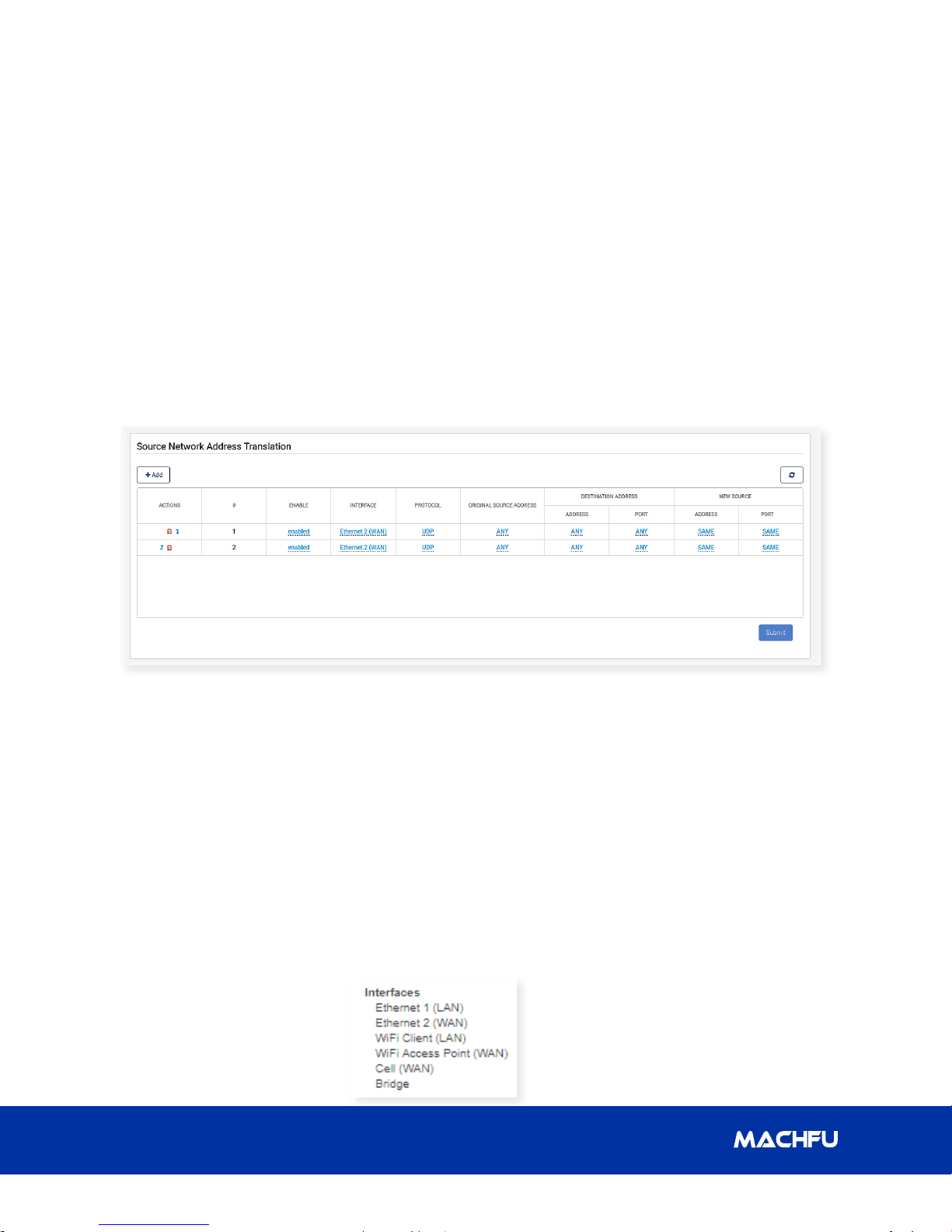
3.5.5 Source Network Address Translation
The Source Network Address Translation (NAT) rules are represented in a tabular format similar to Port
forwarding. The principle of adding, changing, deleting rules and refresh tables are the same as Port
forwarding.
3.5.5.1 Table Columns/Fields
The columns are:
• ACTIONS – It contains icons for deleting
a rule/row or moving it upward or
downward in the table.
• # – It shows the ordering of the rows.
• ENABLE – In display mode, it shows
if the particular rule/row is ‘enabled’
or ‘disabled’. In edit mode, it shows a
dropdown list with values: ‘enabled’ or
‘disabled’. The default value is ‘enabled’.
• INTERFACE – In
display mode, it shows
the chosen interface
for a rule/row. In edit
24
mode, it shows a dropdown list with
the values below. The default value is
‘Ethernet 2 (WAN)’.
• PROTOCOL – In display mode, it shows
the chosen protocol for a rule/row. In
edit mode, it shows a dropdown list
with values: ‘TCP’ or ‘UDP’. The default
value is ‘UDP’.
• ORIGINAL SOURCE ADDRESS – In
display mode, it shows the IP address
of the original source. In edit mode, a
dialog box is shown with the existing
value of the original source address.
The default value is ‘ANY’.
Page 29

MACH-3 Installation and Conguration Manual
3 Gateway Conguration
• DESTINATION ADDRESS
• ADDRESS – In display mode,
it shows the IP address of the
destination. In edit mode, a dialog
box is shown with the existing value
of the destination address. The
default value is ‘ANY’.
• PORT – In display mode, it shows
the port number of the destination.
In edit mode, a dialog box is
shown with the existing value of
the destination port number. The
default value is ‘ANY’.
• NEW SOURCE
• ADDRESS – In display mode, it
shows the IP address of the new
source. In edit mode, a dialog box is
shown with the existing value of the
new source address. The default
value is ‘SAME’.
• PORT – In display mode, it shows
the port number of the new source.
In edit mode, a dialog box is shown
with the existing value of the new
source port number. The default
value is ‘SAME.
3.5.6.1 Table Columns/Fields
• ACTIONS – It contains icons for deleting
a rule/row or moving it upward or
downward in the table.
• # – It shows the ordering of the rows.
• ENABLE – In display mode, it shows
if the particular rule/row is ‘enabled’
or ‘disabled’. In edit mode, it shows a
dropdown list with values: ‘enabled’ or
‘disabled’.
• DESTINATION – In display mode, it shows
the destination address. In the edit mode,
a dialog box is shown with the existing
value of the destination address.
• NETMASK – In display mode, it shows the
size of the subnet prex. In edit mode, a
dialog box is show with the existing value
of the subnet prex size. The default value
is ‘/8’.
• INTERFACE – In display mode, it shows
the chosen interface for a rule/row. In edit
mode, it shows a dropdown list with the
values below. The default value is ‘WAN.
3.5.6 Routes
The default route can be ‘None’, ‘VPN’, or
‘WAN’. The routing rules are represented in
a tabular format. The principle of adding,
changing, deleting rules and refresh tables are
the same as Port forwarding.
Simplifying IoT from edge to enterprise
• GATEWAY – In display mode, it shows the
gateway address. In edit mode, it shows
the existing value of the gateway address.
25
Page 30
3 Gateway Conguration
MACH-3 Installation and Conguration Manual
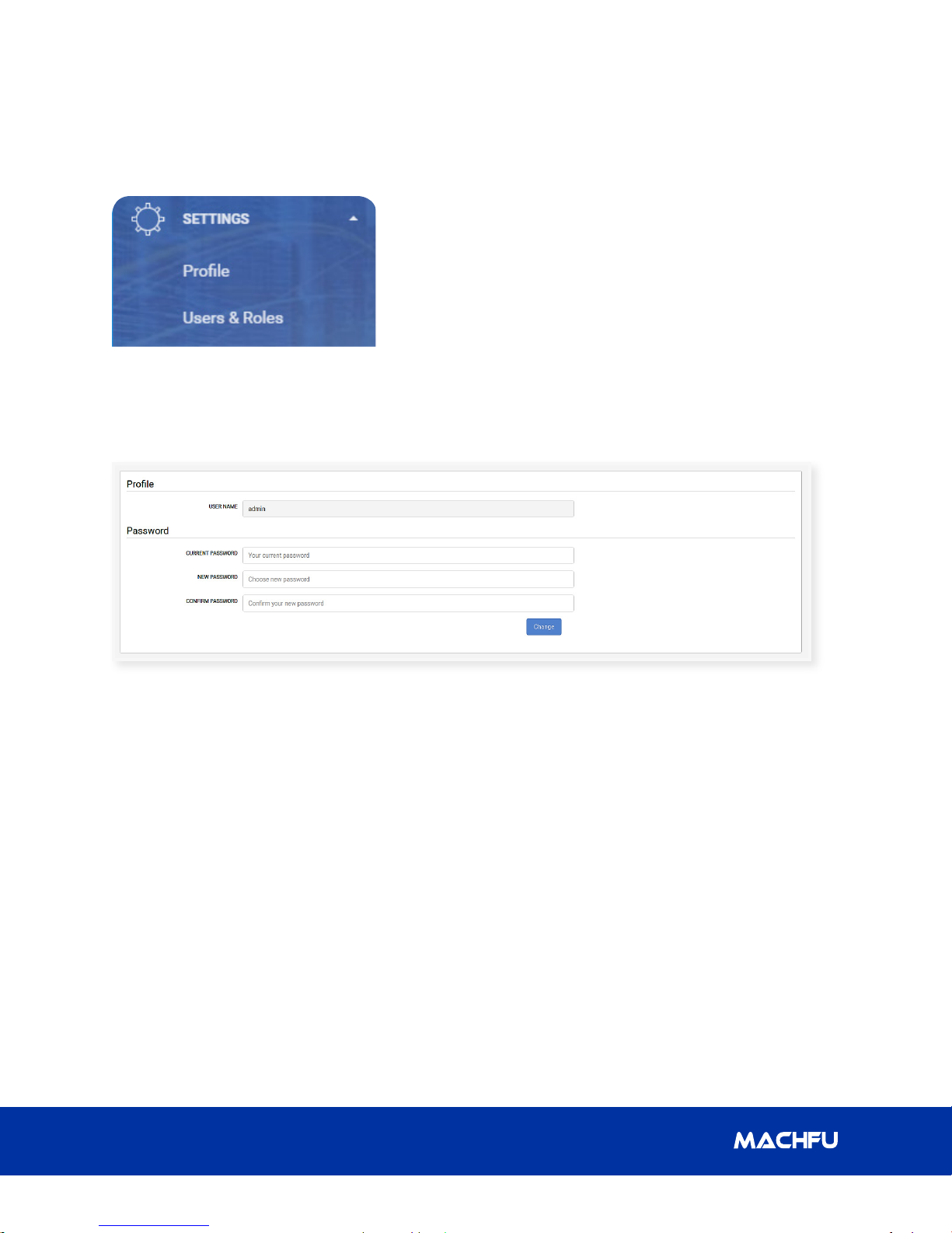
3.6 SETTINGS
The Settings tab has two sections on the left panel: ‘Prole’ and ‘Users & Roles’.
3.6.1 Pr ole
3.6.2 Users & Roles
This section is only visible for users with administrative (admin) role. It allows the admin user to
view all other users of the MACH Gateway, add new users, delete existing users and reset users’
password.
3.6.2.1 Show All Users
The users table displays all the other users of the MACH Gateway. The table columns/elds include:
• ACTION – It contains a clickable icon for deleting an existing user.
• NAME – It displays the identity of the user.
• PASS WORD – The ‘Reset Password’ link is used to reset the user’s password.
• ROLE – It displays the assigned role of the user.
• DATE CREATED – It displays the date the user was created.
• LAST LOGIN – It displays the last date/time the user logged in.
26
Page 31

MACH-3 Installation and Conguration Manual
3 Gateway Conguration
3.6.2.2 Add/Register New User
To register/add a new user to the Gateway,
follow the steps below.
• Click the ‘Add’ button above the users
table. A form section titled ‘New User’
appears.
• Type the name of the user.
• Type the password of the user. The
password must be six characters or more.
• Select the preferred role for the user. The
selections are: ‘Admin’, ‘OEM’, ‘Users’ and
‘Customer’.
• Click the ‘Add’ button to register the new
user or click the ‘Cancel’ button to cancel
the registration.
• A dialog box appears and it indicates if the
registration was successful or not.
• If the registration was successful, the new
user should appear in the users table and
the roles table.
Simplifying IoT from edge to enterprise
27
Page 32

3 Gateway Conguration
MACH-3 Installation and Conguration Manual
3.6.2.3 Delete User
To delete an existing user, follow the steps
below.
• Click on the trash icon in the ‘ACTION’
column.
• A dialog appears to warn the user about
the action.
• Click the ‘OK’ button to conrm the delete
action or click the ‘Cancel’ button to cancel
the action.
3.6.3 Reset User’s Password
To reset the password of a user, follow the
steps below.
• Click the ‘Reset Password’ link in the
‘PASSWORD’ eld/column of the user.
• An inline dialog box appears with the
hint ‘Minimum six characters’ to signify
the password requirement.
• Type the new password for the user.
• Click the check button to set the new
password or the grey button to cancel
the reset action.
• A dialog box appears and it indicates
if the password reset was successful
or not.
• A dialog box appears and it indicates if the
deletion was successful or not.
• If the action was successful, the user’s row
is removed from the table.
28
Page 33

MACH-3 Installation and Conguration Manual
3.6.3.1 Show All Roles
The ‘Roles’ table has two columns/elds:
• ROLES – It displays the acceptable roles for the MACH Gateway.
• USERS – It displays users of the MACH Gateway based on their assigned role.
3 Gateway Conguration
3.7 SYSTEM
The SYSTEM tab has three sections on the left panel: ‘System Upgrade’, ‘General Settings’ and
‘Applications’.
Simplifying IoT from edge to enterprise
29
Page 34
3 Gateway Conguration
MACH-3 Installation and Conguration Manual
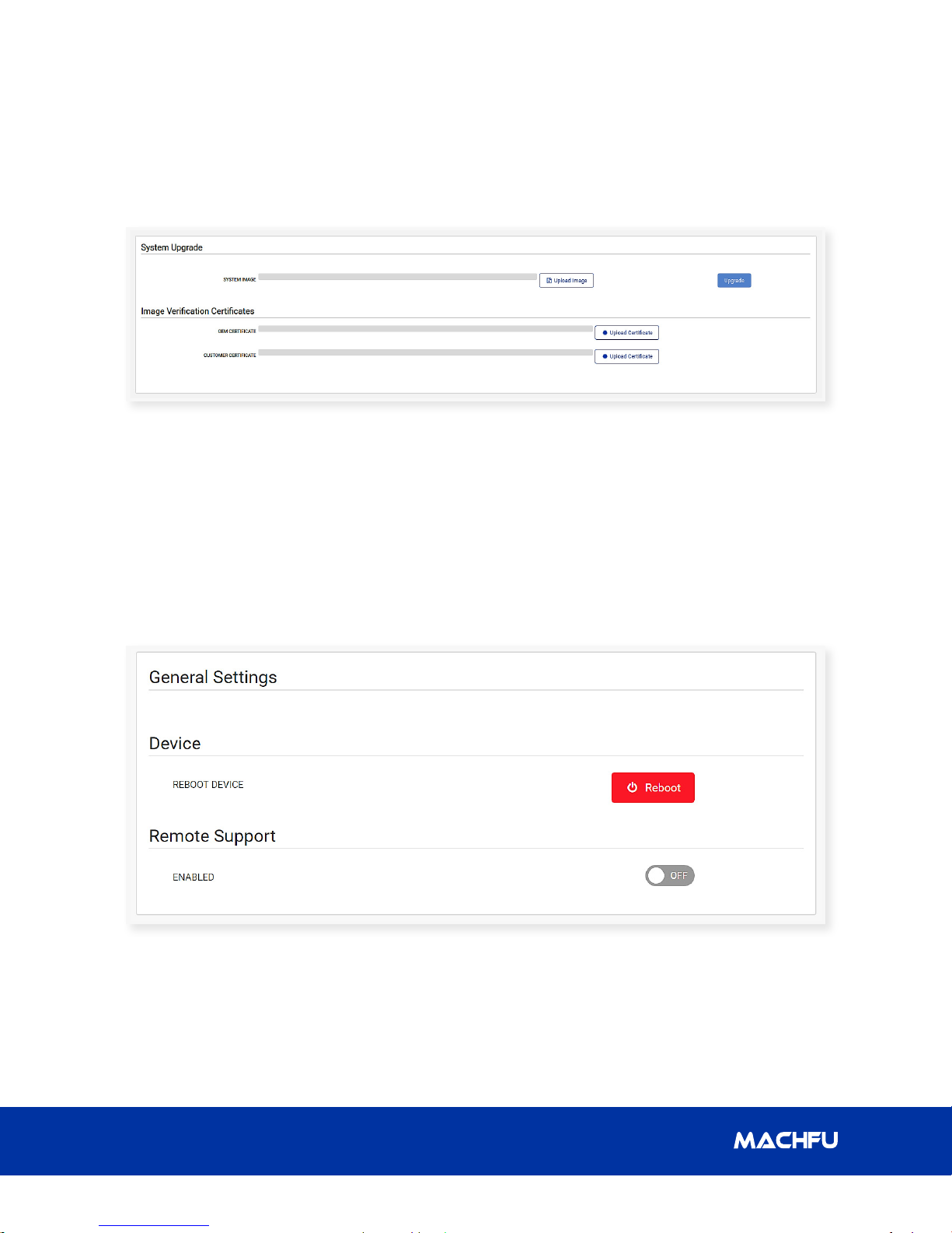
3.7.1 System Upgrade
This page allows the user with the roles ‘admin’, ‘oem’ or ‘customer’ to perform the system image
update. The following steps show how to update the system image of a MACH Gateway.
• Click the ‘Upload Certicate’ button to select the Image verication certicate. The ‘oem’ user
should upload an OEM certicate while the ‘customer’ user should upload a Customer certicate.
The ‘admin’ user can upload either an OEM certicate or a Customer certicate.
3.7.2 General Settings
This page allows any user to reboot the MACH Gateway and set remote support option.
3.7.2.1 Reboot Device
To reboot the MACH Gateway, follow the steps below.
• Click the ‘REBOOT’ button.
• A dialog appears and it warns the user about the action to be performed.
30
Page 35

MACH-3 Installation and Conguration Manual
• Click the ‘Reboot’ button to conrm the
action or click the ‘Cancel’ button to
cancel the reboot action.
3.7.2.2 Remote Support
To set the Remote Support option, follow the
steps below:
3 Gateway Conguration
• A pop-up dialog appears and it
informs the user if the chosen action is
successful or not.
• Set the ‘ENABLED’ button to ‘ON’ to
enable remote support or set it to ‘OFF’
to disable it.
• A pop-up dialog appears and it warns
the user about the intended action.
• Click the ‘OK’ button to conrm the
action or click the ‘Cancel’ button to
cancel the action.
Simplifying IoT from edge to enterprise
31
Page 36

MACH-3 Installation and Conguration Manual3 Gateway Conguration
3.7.3 Applications
The applications table shows some applications/services running on the MACH Gateway. There
are two pre-dened categories of applications/services: System Apps and Machfu Apps.
3.7.3.1 Categories
• System Apps – These apps/services are always running and are essential to the overall operation
of the MACH Gateway. The user cannot uninstall or close them from the applications table.
• Machfu Apps – These apps/services can be uninstalled or closed from the table.
3.7.3.2 Table Columns/Fields
• ACTION – This contains the delete icon for ‘Machfu Apps’. This column appears only for users
with ‘admin’ role.
• PACKAGE – This shows the package name of the application/service.
• VERSION – This shows the version name of the application/service.
• VERSION CODE – This shows the version code of the application/service.
• STATUS – This indicates if the application/service is running (ENABLED) or not (DISABLED).
• ENABLE – This contains a checkbox that allows the user to start or stop ‘Machfu Apps’. The
checkbox is disabled for ‘System Apps’. This column appears only for users with ‘admin’ role.
32
Page 37

MACH-3 Installation and Conguration Manual
3 Gateway Conguration
3.7.3.3 Delete/Uninstall App
To delete a ‘Machfu app’, follow the
instructions below:
• Click the icon in the ‘ACTION’ eld.
• A pop-up dialog appears and it warns the
user that the selected app/service would
be uninstalled.
• Click the ‘OK’ button to conrm deleting/
uninstalling the app or click the ‘Cancel’
button to cancel the action.
3.7.4 Start/Stop App
To start(enable) or stop(disable) an app,
follow the steps below:
• Click the checkbox in the ‘ENABLE’ eld to
change the running state of the app.
• A pop-up dialog appears and it warns the
user about changing the state of the app.
• Click the ‘OK’ button to conrm the action
or click the ‘Cancel’ button to cancel the
action.
• A pop-up dialog appears and it informs
the user if the app has been uninstalled
successfully or
not.
• The table refreshes automatically to
show that the app has been removed/
uninstalled.
• A pop-up dialog appears and it informs
the user if the action is successful or not.
Simplifying IoT from edge to enterprise
33
Page 38

3 Gateway Conguration
MACH-3 Installation and Conguration Manual
• The table refreshes automatically to
show that the updated status of app.
34
Page 39

MACH-3 Installation and Conguration Manual
4 Regulator y Notices
4. Regulatory
Notices
FCC Statement
This equipment has been tested and found
to comply with the limits of a Class A digital
device, pursuant to part 15 of the FCC Rules.
These limits are designed to provide reasonable
protection against harmful interference when
the equipment is operated in a commercial
environment. This equipment generates,
uses, and can radiate radio frequency energy
and, if not installed and used in accordance
with the instruction manual, may cause
harmful interference to radio communications.
Operation of this equipment in a residential area
is likely to cause harmful interference in which
case the user will be required to correct the
interference at his own expense.
interference, including interference that may
cause undesired operation of the device.
Industry Canada Statement
This device complies with Industry Canada’s
licence-exempt RSSs. Operation is subject to
the following two conditions:
(1) This device may not cause interference; and
(2) This device must accept any interference,
including interference that may cause
undesired operation of the device.
Le présent appareil est conforme aux CNR
d’Industrie Canada applicables aux appareils
radio exempts de licence. L’exploitation est
autorisée aux deux conditions suivantes:
(1) l’appareil ne doit pas produire de brouillage;
FCC Radiation Exposure
Statement
This device complies with FCC radiation
exposure limits set forth for an uncontrolled
environment and it also complies with Part
15 of the FCC RF Rules. This equipment must
be installed and operated in accordance with
provided instructions and the antennae used
for this transmitter must be installed to provide
a separation distance of at least 20 cm from all
people and must not be co-located or operating
in conjunction with any other antenna or
transmitter. End-users and installers must be
provided with antenna installation instructions
and consider removing the no-collocation
statement.
This device complies with Part 15 of the FCC
Rules. Operation is subject to the following
two conditions: (1) this device may not cause
interference, and (2) this device must accept any
(2) l’utilisateur de l’appareil doit accepter tout
brouillage radioélectrique subi, même si le
brouillage est susceptible d’en compromettre le
fonctionnement.
This transmitter must not be co-located
or operating in conjunction with any other
antenna or transmitter.
This equipment should be installed and
operated with a minimum distance of 20
centimeters between the radiator and your
body.
Cet émetteur ne doit pas être Co-placé ou ne
fonctionnant en même temps qu'aucune autre
antenne ou émetteur.
Cet équipement devrait être installé et actionné
avec une distance minimum de 20 centimètres
entre le radiateur et votre corps.
Simplifying IoT from edge to enterprise
35
Page 40

4 Regulator y Notices
Industry Canada Radiation
Exposure Statement
This radio transmitter with model: Mach3
Gateway has been approved by Industry
Canada to operate with the antenna types
listed below with the maximum permissible
gain and required antenna impedance for
each antenna type indicated. Antenna types
not included in this list, having a gain greater
than the maximum gain indicated for that
type, are strictly prohibited for use with this
device.
Le présent émetteur radio with model: Mach3
Gateway a été approuvé par Industrie Canada
pour fonctionner avec les types d'antenne
énumérés ci-dessous et ayant un gain admissible
maximal et l'impédance requise pour chaque
type d'antenne. Les types d'antenne non inclus
dans cette liste, ou dont le gain est supérieur au
gain maximal indiqué, sont strictement interdits
pour l'exploitation de l'émetteur.
MACH-3 Installation and Conguration Manual
No. Brand Model name Antenna type Connector Gain (dBi)
1 Taoglas GW.05 Monopole Standard RP-SMA (M) 1.25
36
Page 41

MACH-3 Installation and Conguration Manual
5 Appendix
5. Appendix
5.1 Cellular Bands
The supported bands are 2, 4, 5, 6 and 13.
5.2 Antenna Specication
The Mach-3 Gateway is a professionally-installed equipment. The Radio Frequency (RF) output
power does not exceed the maximum limit allowed in the country of operation.
CAUTION: Unauthorized antennae, modications, or attachments may damage the device
and potentially violate regulations.
NOTE: Use only the supplied or an equivalent replacement antenna.
NOTE: Modications to the device or use of unauthorized antennae as not expressly
approved by Machfu is the sole responsibility of the user, congurator or operator, who
must reassess the equipment in accordance to all applicable international Safety, EMC, and
RF standards.
The Machfu-authorized antenna specications are as follows:
• Mobile Broadband (SMA male)
– Main: Dipole
– LTE Auxiliary: Dipole
Frequency Typ. Avg Gain (dBi) Peak Gain (dBi)
698-806 -3 3
824-894 -2 3
880-960 -2 3
1710 -188 0 -1 4.5
1850-1990 -1 4.5
1920 -2170 -1 4.5
• Mobile Broadband (SMA male)
Frequency Typ. Avg Gain (dBi) Peak Gain (dBi)
2200-2483 1.5 4
• GPS: Monopole (SMA male)
Frequency Typ. Avg Gain (dBi) Peak Gain (dBi)
1571 - 1578 28 -
1601-1603 28 -
Simplifying IoT from edge to enterprise
37
Page 42

MACH-3 Installation and Conguration Manual
5.3 Contacting Machfu
For technical assistance or customer service issues please contact support@machfu.com.
38
 Loading...