

Page 1
*
*
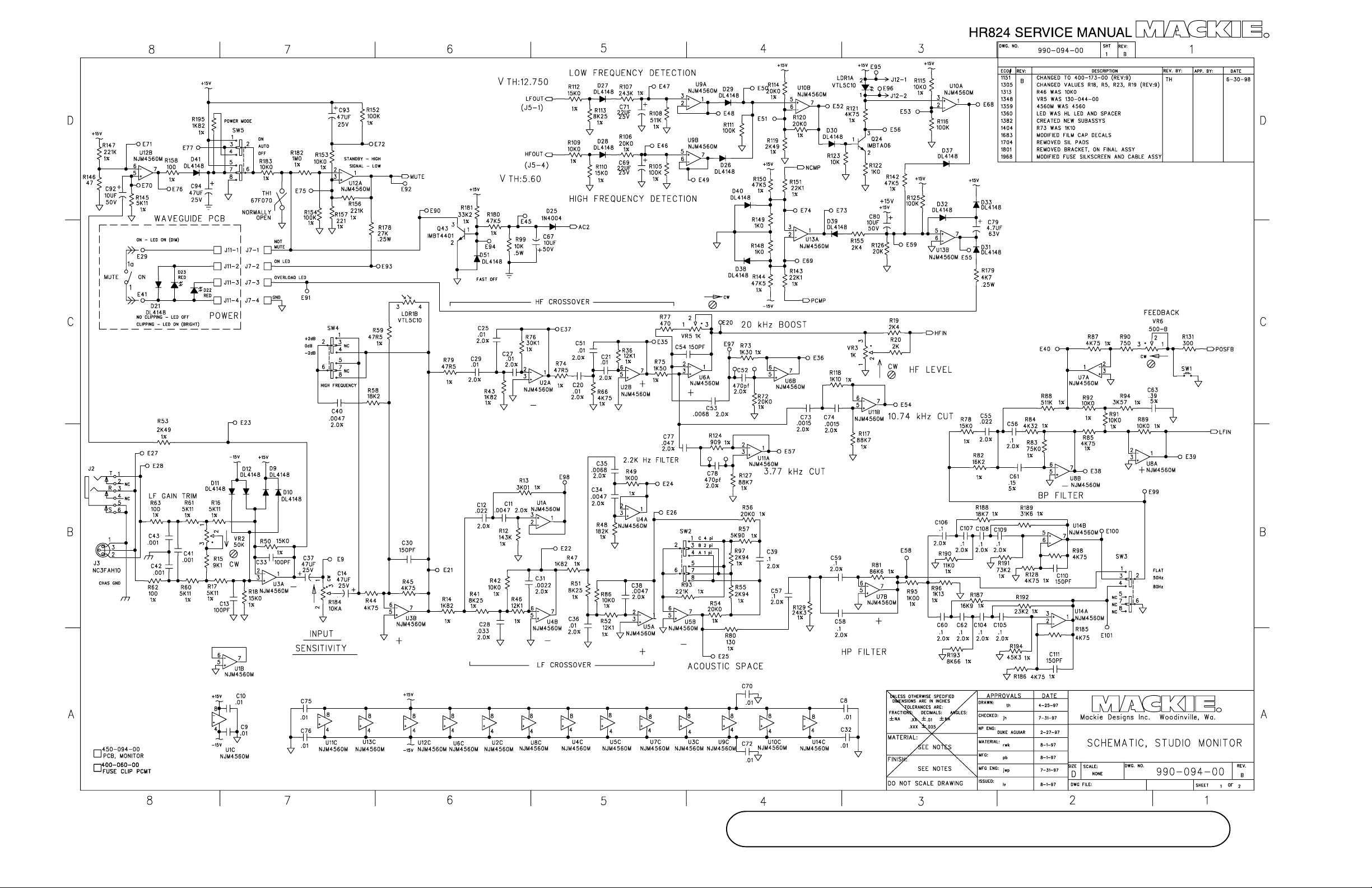
Note: The only difference between the
*
Rev A and Rev B parts are that VR5, R73
and R46 may have different values on the
Rev A board. See the parts list for details.
(There is no need to change to the new
parts if you have a Rev A board).
©1998, ©1999 Mackie Designs Inc. All Rights Reserved
*
HR824 SCHEMATIC REV A and B sheet 1 of 2
A-1
Page 2
A-2
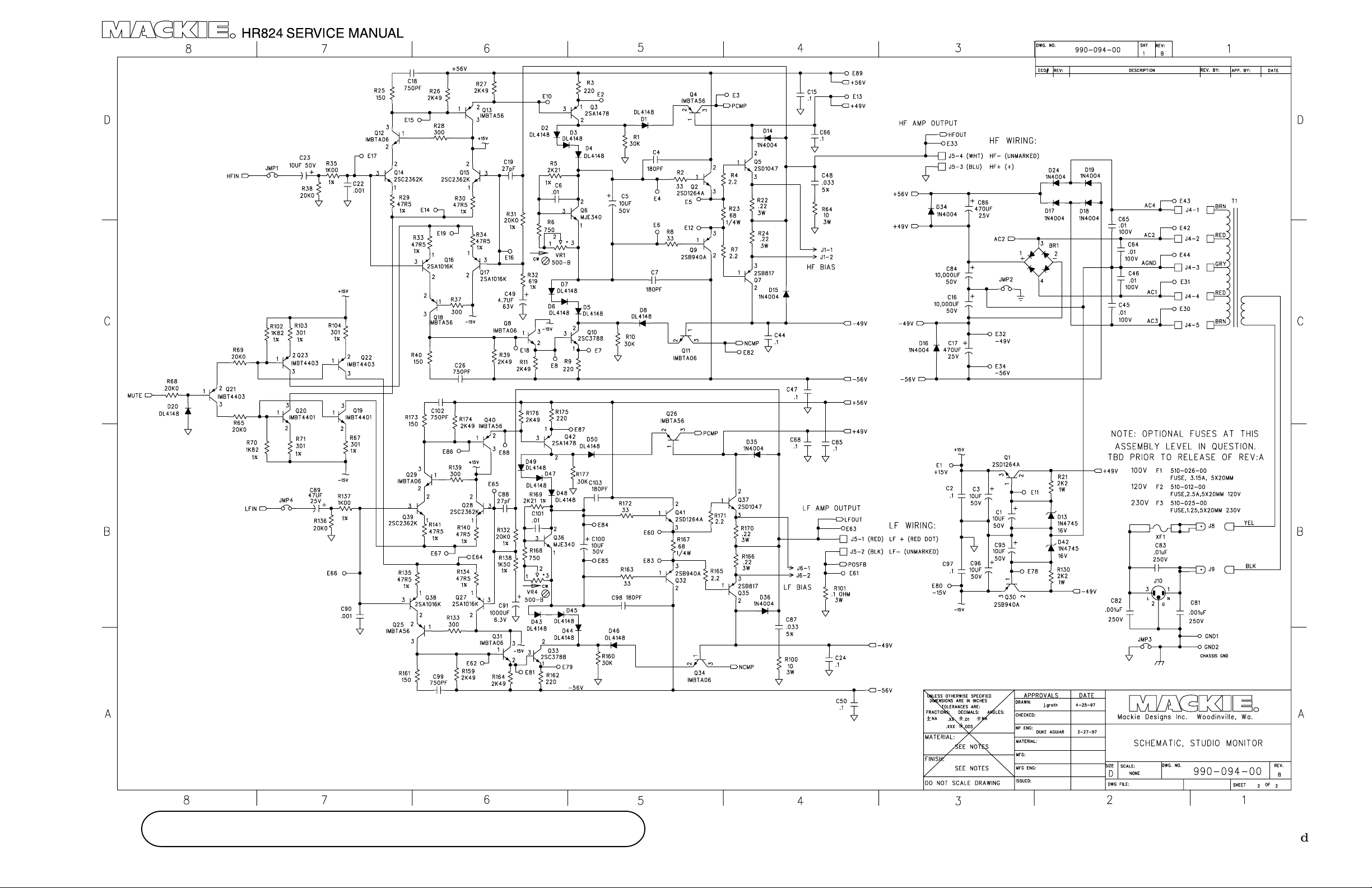
HR824 SCHEMATIC REV A and B sheet 2 of 2
©1998, ©1999 Mackie Designs Inc. All Rights Reserved
Page 3
310-029-00
NPN
2SD1264A
Q1
310-029-00
NPN
2SD1264A
Q2
310-025-00
NPN
2SD1047
Q5
310-037-00
NPN
MJE340
Q6
310-024-00
PNP
2SB817
Q7
310-028-00
PNP
2SB940A
Q9
b e b e
b e
e b
b e
b e
J2
1/4" STEREO JACK
400-166-00
R184
J3
XLR (FEMALE)
CONNECTOR
400-131-00
SW2
e b e b
Q30
2SB940A
PNP
310-028-00
Q32
2SB940A
PNP
310-028-00
©1998, ©1999 Mackie Designs Inc. All Rights Reserved
e b e b
Q35
2SB817
PNP
310-024-00
b e
Q36
MJE340
NPN
310-037-00
Q37
2SD1047
NPN
310-025-00
e b
Q41
2SD1264A
NPN
310-029-00
TH1
67F070
THERMOSTAT
500-026-00
IEC CONNECTOR
SW5 SW3 SW4
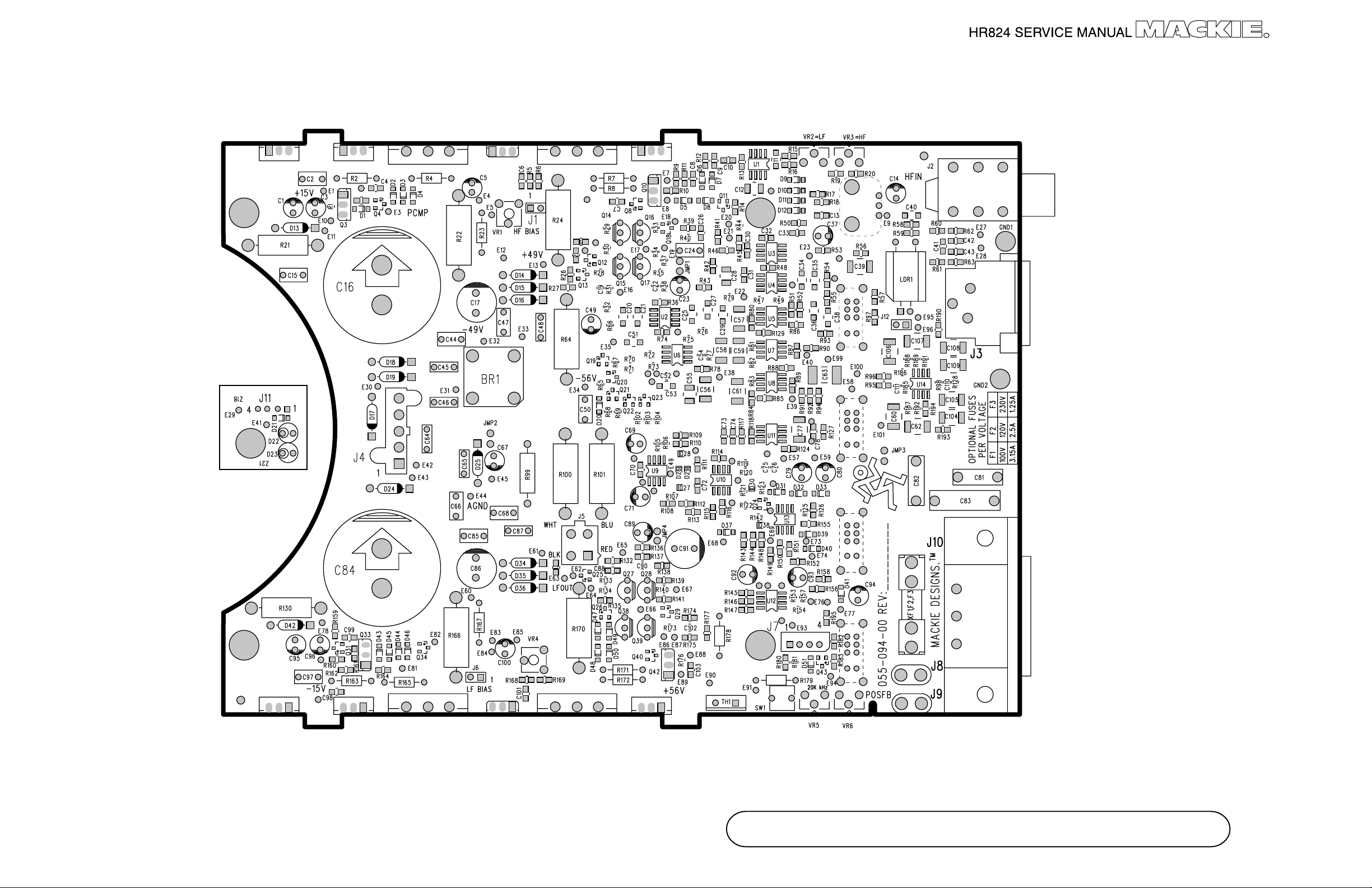
HR824 BOARD REV A
J10
400-132-00
A-3
Page 4
Component
Bottom of
side of
board
board
A-4
HR824 BOARD REV A
©1998, ©1999 Mackie Designs Inc. All Rights Reserved
Page 5

310-029-00
NPN
2SD1264A
Q1
310-029-00
NPN
2SD1264A
Q2
310-025-00
NPN
2SD1047
Q5
310-037-00
NPN
MJE340
Q6
310-024-00
PNP
2SB817
Q7
310-028-00
PNP
2SB940A
Q9
b e b e
b e
e b
b e
b e
J2
1/4" STEREO JACK
400-166-00
J3
XLR (FEMALE)
CONNECTOR
400-131-00
Note: The main difference
between the Rev A and
Rev B boards is in the
trace layout at this end of
the board
e b e b
Q30
2SB940A
PNP
310-028-00
©1998, ©1999 Mackie Designs Inc. All Rights Reserved
Q32
2SB940A
PNP
310-028-00
e b e b
Q35
2SB817
PNP
310-024-00
b e
Q36
MJE340
NPN
310-037-00
Q37
2SD1047
NPN
310-025-00
e b
Q41
2SD1264A
NPN
310-029-00
TH1
67F070
THERMOSTAT
500-026-00
HR824 BOARD REV B, Oct 98
J10
IEC CONNECTOR
400-132-00
A-5
Page 6

Component
side of
board
Bottom of
board
A-6
HR824 BOARD REV B Oct 98
©1998, ©1999 Mackie Designs Inc. All Rights Reserved
Page 7

©1998, ©1999 Mackie Designs Inc. All Rights Reserved
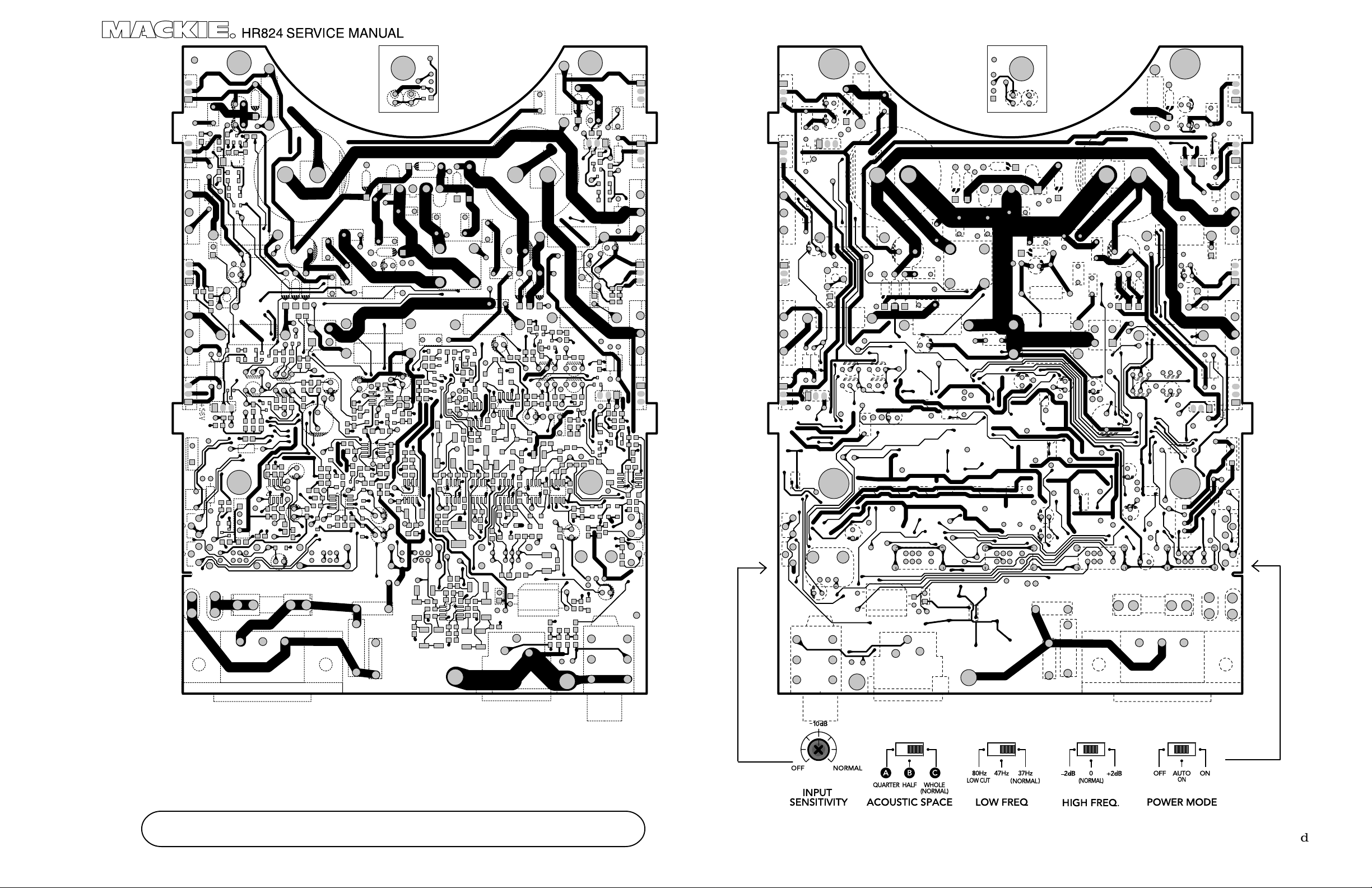
HR824 BOARD
A-7
Page 8

A-8
HR824 ASSEMBL Y
©1998, ©1999 Mackie Designs Inc. All Rights Reserved
Page 9

©1998, ©1999 Mackie Designs Inc. All Rights Reserved
HR824 ASSEMBL Y
A-9
Page 10

A-10
HR824 ASSEMBL Y
©1998, ©1999 Mackie Designs Inc. All Rights Reserved
Page 11

SWITCH SIDE
MARKED "E"
IS CLOSEST TO
"ON/OFF" MARKING
ON WAVEGUIDE
7
56
89
12
43
WAVEGUIDE
TIGHTENING
SEQUENCE
Note: screw down until the
waveguide is flush/level with
the surrounding wood. The
max torque is approximately
12 inch pounds.
Note: if you ever strip out a
hole, this can be fixed by
pushing a piece of tree wood
dowel fully into the hole, then
put in the screw.
The suggested dowel size is
20mm long x 5mm dia.
©1998, ©1999 Mackie Designs Inc. All Rights Reserved
HR824 ASSEMBL Y
A-11
Page 12

Detail F
See Detail F
passive
gasket
MDF
Fill with hot glue, flush,
never above MDF.
0.5"
rolled up
sticky gasket
TWEETER FOAM
MAKE SURE IT IS PUSHED ALL THE
WAY DOWN T OW ARDS THE TWEETER
A-12
HR824 ASSEMBL Y
WOOFER FOAM
GLUE TO H BRACE WITH LOCTITE 410
AND BLACK MAGIC ACCELERATOR
MAKE SURE THE FOAM DOES NOT
TOUCH THE PASSIVE RADIATOR.
©1998, ©1999 Mackie Designs Inc. All Rights Reserved
Page 13

RED
J5-1
BLACK
PCB (J5)
PCB GROUND (GD1) TO REAR COVER
PCB GROUND (GD2)
J5-2
J5-4
J5-3
WHITE
BLUE
WOOFER
WOOFER
TWEETER
TWEETER
TO BRACKET
J7
J4
J5
PCB (J7)
WAVEGUIDE PCB
TRANSFORMER
J7-1
J7-2
J7-3
J7-4
E-29
E-41
BRN
RED
GRY
RED
YEL
*
BLK
YELLOW FOR 120V TRANSFORMERS
*
WHITE FOR 230V TRANSFORMERS
*
BLUE FOR 100V TRANSFORMERS
*
J11-1
J11-2
J11-3
J11-4
J4-1
J4-2
J4-3
J4-4
J4-5BRN
J8
J9
WAVEGUIDE
PCB J11
WIRING DIAGRAM
SWITCH
PCB (J4)
PCB (J8)
PCB (J9)
J8&9
©1998, ©1999 Mackie Designs Inc. All Rights Reserved
THE WIRES ARE CAREFULLY
TYRAPPED AT THE FACTORY.
TAKE CARE THAT THE WIRES ARE
TIGHT AND DO NOT TOUCH THE
PASSIVE RADIATOR, OR HANG DOWN
AND TOUCH THE CIRCUIT BOARD .
HR824 ASSEMBL Y
A-13
 Loading...