

Page 1
8•BUS
Page 3 is interactive
Go To Bulletins
8•BUS MIXING CONSOLE
SERVICE MANUAL
1993, 1999 MACKIE DESIGNS, INC.
820-177-00
Page 2
SERVICE ON THIS EQUIPMENT IS TO BE PERFORMED BY
EXPERIENCED REPAIR TECHNICIANS ONLY
2
Page 3
CONTENTS
Click on any item to open that page
ALL BOARDS
INTRODUCTION .................................................................................3
Technical Support ........................................................................ 3
Disclaimer.......................................................................................3
BLOCK DIAGRAM ............................................................................. 4
PARTS.......................................................................................5-8, A-1
FOLD-OUT SECTIONS: (Schematics and PCB layouts)
Mic/Line Preamp board ........................................................ 08-1
Channel board ....................................................................... 09-1
Output board ......................................................................... 10-1
Meter board ............................................................................ 11-1
Jack Field board..................................................................... 12-1
Tape Output board............................................................... 13-1
Tape Input board ................................................................... 14-1
Power Supply .......................................................................... 15-1
Expander board ..................................................................... 19-1
Power Distribution board....................................................... 20-1
Expander Output board ....................................................... 21-1
Analog Meter board ............................................................. 22-1
LED Meter board .................................................................... 23-1
INTRODUCTION
SERVICE ON THIS EQUIPMENT IS TO BE PERFORMED BY
EXPERIENCED REPAIR TECHNICIANS ONLY
This manual contains basic service information. It is essential that you have a
copy of the user’s manual as this contains the complete operating instructions.
SERVICE TECHNICAL ASSISTANCE
Mackie Designs, Service Technical Assistance, is available 8AM - 5PM PST, Monday through
Friday for Authorized Mackie Service Centers, at 1-800-258-6883. Feel free to call with any
questions and speak with a carefully-calibrated technician. If one is not available, leave
a detailed message and a qualified Mackoid will return your call asap.
DISCLAIMER
The information contained in this manual is proprietary to Mackie Designs, Inc. The entire
manual is protected under copyright and may not be reproduced by any means without
express written permission from Mackie Designs, Inc.
3
Page 4
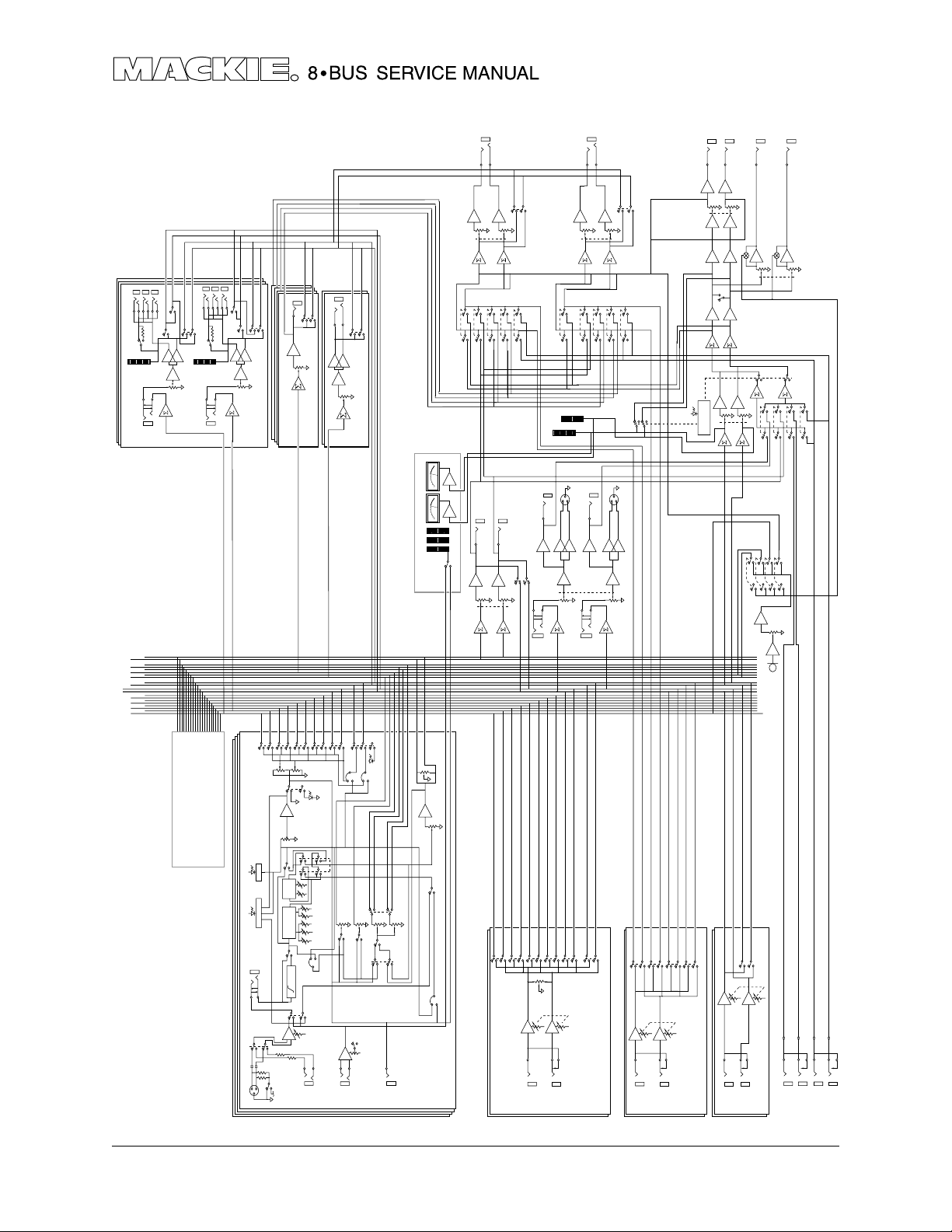
BLOCK DIAGRAM
•
•
L-MIX-B
AUX 5
AUX 3
AUX 1
L-SOLO
R-BUS
L-BUS
BUS 7
BUS 5
BUS 3
BUS 1
•
•
•
•
•
SUB OUTS 1, 9 & 17
+4/-10
•
METER
•
•
INSERT
R-MIX-B
AUX 6
AUX 4
AUX 2
R-SOLO
BUS 8
BUS 6
BUS 4
BUS 2
•
•
•
•
•
SUB OUTS 2, 10 & 18
+4/-10
METER
•
•
INSERT
L + R
•
•
SOLO
•
•
R MIX
•
•
•
•
-
+
•
•
FADER
SUB MSTR
(#3 - 8 IDENTICAL)
•
L + R
•
L MIX
SOLO
•
•
-
+
•
FADER
SUB MSTR
SUB MASTER 1 & 2
NOTE: ALL SWITCHES SHOWN IN DISENGAGED (UP) POSITION
•
•
•
•
•
•
•
•
•
•
•
•
•
•
•
•
•
•
•
•
•
OPTIONAL 24•E
EXPANDER CONSOLE
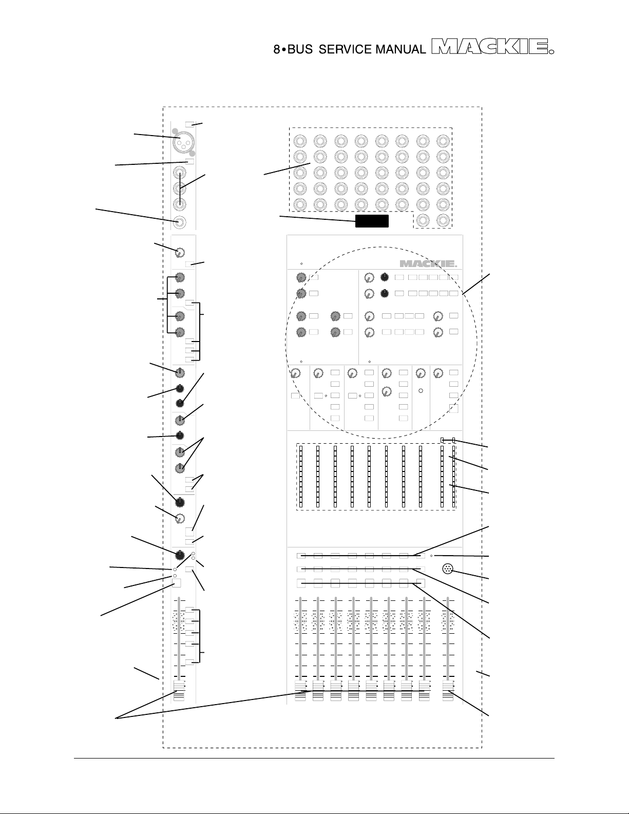
24-CHANNEL MACKIE 8•BUS
•
•
•
1-2
PAN
–20dB
0L
INSERT
•
•
MIC/LINE
•
•
•
2
3
1
MIC IN
•
LEVEL
•
•
3-4
•
•
•
•
•
•
EQ
IN/OUT
•
EQ
SHELVING
EQ
PARAMETRIC
IN/OUT
LO CUT
75Hz
•
+
(PER 8 CHANNELS)
PHANTOM POWER
AUX OUT
•
•
•
•
•
•
CHAN
FADER
•
MIDLO LOHI
MID
HI
••
HPF
•
-
•
5-6
•
•
•
•
•
SOLO
•
(#4, 5, 6 IDENTICAL)
AUX SEND 3
•
•
•
7-8
•
•
•
•
MUTE
SPLIT
HI/LO EQ
TO MIX B
•
•
•
FREQ
GAIN
"Q"
FREQ
GAIN
PRE EQ
TO AUX MOD
FLIP
TRIM
IN
LINE
•
AUX OUT
•
+
LEVEL
•
•
L/R
•
•
POST
•
•
-
•
•
•
•
AUX 1
•
PRE
•
•
-
+
IN
TAPE
•
•
SOLO
•
(#2 IDENTICAL)
AUX SEND 1
•
•
•
•
•
SOLO
PFL MOD
•
AUX 3
AUX 5
AUX 2
•
SOURCE
PRE
POST
PRE
POST
•
•
(PER 8 CH'S)
+4dBU/–10dBV Select
•
•
•
•
•
•
•
•
AUX 4
AUX 6
SHIFT
PRE
POST
•
OUT
DIRECT
PHONES 1
L
LEVEL
PHONES 1
MONITOR
•
•
SOURCE
PHONES 1
vu
vu
TAPE IN
CH. OUT
•
LEVEL
CHANNEL MIX-B SOURCE MOD
•
•
OPTIONAL METER BRIDGE
SELECT
GLOBAL
•
•
PAN
•
••
FLIP SW
MIX-B
SOURCE
•
INPUT
1 OF 16 (24) (32)
OUTPUT
•
•
AUX 3/4
MIX-B
•••
•
•
•
•
•
L
MIX-B OUTPUT
MIX B
MASTER
•
•
•
•
SOLO
IS SELECTED)
R
(DEFEATED WHEN
CNTRL RM SOURCE
•
•
•
AUX 5/6
EXTERNAL
MONITOR
•
••
•
••
•••
•
•
R
PHONES 2
L UNBAL OUTPUT
•
TO
MIX-B
L/R MIX
•
•
SOURCE
L METER
INSERT
•
R METER
1
2
+
•
•
INSERT
•
3
-
•
•
•
•
•
•
•
•
•
•
•
•
1-2
3-4
•
L/R
7-8
5-6
•
•
•
•
•
BALANCE
LEVEL
••
LEFT
RIGHT
(MONO)
OUTPUT
PHONES 2
SOLO
L
R
•
•
LEVEL
PHONES 2
•
•
•
•
AUX 3/4
MIX-B
EXTERNAL
AUX 5/6
•
•
•
•
•
•••
•
•
•
•
1
2
3
L BAL OUTPUT
•
R UNBAL OUTPUT
•
L/R
MIX
FADER
•
•
INSERT
•
•
SOLO
•
+
•
•
R BAL OUTPUT
-
•••••
(#2 IDENTICAL)
STEREO AUX RETURN 1
(DEFEATED WHEN
CNTRL RM SOURCE
•
•
PHONES 1
•
•
LEFT
(MONO)
IS SELECTED)
•
•
•
•
•
•
•
L/R
SOLO
PHONES 2
•
•
•
•
•
LEVEL
RIGHT
STEREO AUX RETURN 3
L
STUDIO
OUTPUT
•
LEVEL
STUDIO
•
••
MONO
•
SOLO
CONTROL
•
•
•
•••
•
•
•
•
(#4 IDENTICAL)
L
R
STUDIO
OUTPUT
CNTRL RM
•
••
•
•
•
•
•
•
•
•
SOLO
LEVEL
L/R MIX
TO AUX 1
TO AUX 2
TALKBACK:
•
MIC LEVEL
MIC
•
•
•
•
•
•
•
•
To on-ramp #257
of the Santa Ana Freeway
L/R
SOLO
•
•
LEVEL
•
(#6 IDENTICAL)
LEFT
RIGHT
(MONO)
STEREO AUX RETURN 5
OUTPUT
LEVEL
CNTRL RM
•
•••
MIX-B
TO TAPE/
SUBMASTER
•
•
•
R
OUTPUT
CNTRL RM
••
•••
2-TK
TO PHONES
(AND STUDIO)
•
•
•
L
2-TK IN
SOURCE
MONITOR
EXTERNAL
R
2-TK IN
•
•
IN L
EXTERNAL
PAD LOGIC
CONTROL ROOM
•
IN R
EXTERNAL
4
Page 5
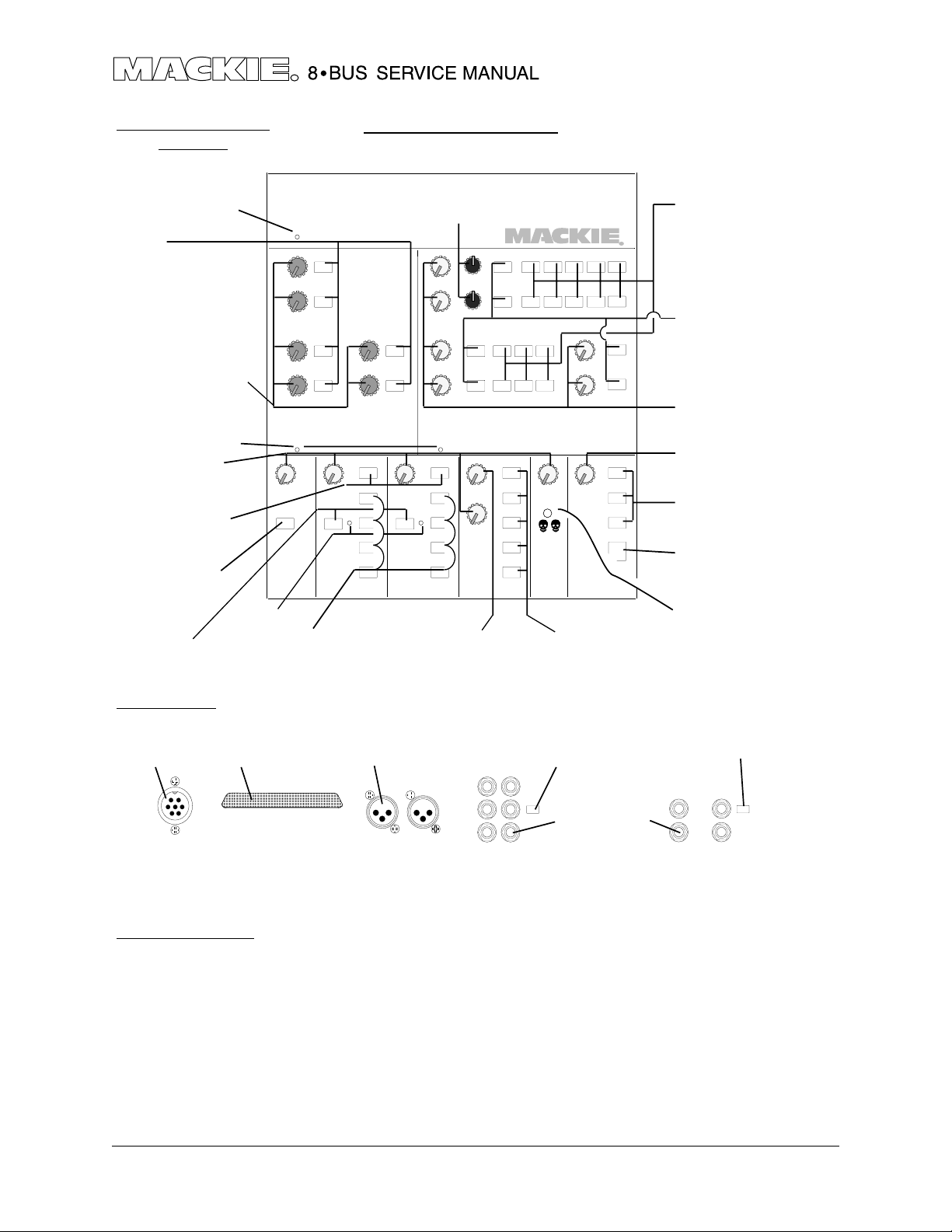
QUICK PARTS
XLR - female jack
400-223-00
*MIC/LINE
button 760-003-00
switch 500-018-00
BNC
400-010-00
GAIN TRIM (off-white)
knob 760-023-00
5k pot 130-020-00
AUX SENDS (magenta)
knob 760-016-00
50k pot 130-003-00
EQ LEVEL (blue-gray)
knob 760-017-00
50k pot 130-002-00
EQ FREQ (dark gray)
knob 760-048-04
50k pot 130-017-00
EQ FREQ (dark gray)
knob 760-048-04
500k pot 130-023-00
MIX B Pan (dark gray)
knob 760-018-00
50k pot 130-003-00
MIX B Level (off-white)
knob 760-023-00
50k pot 130-003-00
PAN (dark gray)
knob 760-018-00
50k pot 130-063-02
RED LED
304-001-00
YELLOW LED
304-003-00
MUTE
button 760-108-00
switch 500-018-00
END CAP - LEFT
760-022-00
*PHANTOM POWER
button 760-003-00
switch 500-018-00
1/4"- female jack
400-214-00
RUBBER PLUG
FLIP
button 760-003-00
switch 500-018-00
AUX - pre/shift/source
button 760-003-00
switch 500-018-00
EQ BWidth (dark gray)
knob 760-048-04
50k pot 130-003-00
EQ LEVEL (blue-gray)
knob 760-017-00
10k pot 130-022-02
HI/LO EQ (blue-gray)
knob 760-017-00
50k pot 130-002-00
EQ - in / low cut
button 760-108-00
switch 500-018-00
MIX B - split
button 760-011-00
switch 500-012-00
MIX B - source
button 760-003-00
switch 500-018-00
GREEN LED
304-004-00
SOLO
button 760-013-00
switch 500-012-00
BUS ASSIGN
button 760-008-00
switch 500-018-00
sheet 1of 2
Exploded Master
Section - see sh. 2
RED LED rect
304-007-00
YELLOW LED rect
304-008-00
GREEN LED rect
304-009-00
SUB-M SOLO
button 760-013-00
switch 500-012-00
RED LED
304-001-00
TALKBACK MIC
480-001-00
SUB-M MONO
button 760-013-00
switch 500-018-00
SUB-M ASSIGN
button 760-002-00
switch 500-018-00
END CAP - RIGHT
760-021-00
VOLUME
gnob 760-024-01
10k pot 130-016-00
*NOTE: CHANNEL MIC/LINE, PHANTOM POWER SWITCHES ALSO REQUIRE -
SWITCH BUTTON EXTENDER PART#760-015-00
MASTER VOLUME
knob 760-024-01
10k pot 130-014-00
05/99
5
Page 6
EXPLODED MASTER
SECTION
RED LED 304-001-00
SOLO
button 760-013-00
switch 500-012-00
AUX SENDS (magenta)
knob 760-016-00
50k pot 130-003-00
RED LED 304-001-00
LEVEL (off-white)
knob 760-023-00
50k pot 130-012-00
MONITOR ASSIGN
button 760-013-00
switch 500-012-00
MIX B > L/R MIX
button 760-108-00
switch 500-018-00
RED LED
SOLO
button 760-013-00
switch 500-012-00
304-001-00
8 Bus Quick Parts
PHONES SOURCES
button 760-013-00
switch 500-018-00
AUX PAN (dark gray)
knob 760-048-04
50k pot 130-003-00
STUDIO LEVEL (off-white)
knob 760-023-00
25k pot 130-004-02
page 2 of 2
AUX RET ASSIGN
button 760-108-00
switch 500-018-00
AUX RET SOLO
button 760-013-00
switch 500-012-00
AUX RETURNS (off-white)
knob 760-023-00
50k pot 130-012-00
TB - LEVEL
knob 760-023-00
50k pot 130-003-00
TB - DESTINATION
button 760-003-00
switch 500-005-00
TB - PH AND STUDIO
button 760-108-00
switch 500-005-00
RUDE RED LED
304-002-00
MONITOR SOURCES
button 760-003-00
switch 500-018-00
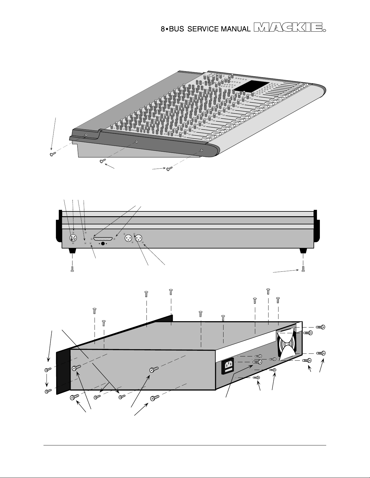
REAR PANEL
7 PIN CIRC male
400-045-00
37 PIN D-SUB female
400-047-00
*
NOTE: SUBMASTER/T APE OUTPUT & TAPE RETURN LEVEL SWITCHES ALSO REQUIRE -
MISCELLANEOUS:
Extrusion ARMREST
16−8, 24−E 551-006-00
24−8 551-007-00
32−8 551-008-00
METER BRIDGE MOUNTING KIT
(080-030-00 - includes instructions
and mounting hardware)
SUB /TAPE OUT*
XLR - male jack
400-223-00
SWITCH BUTTON EXTENDER P AR T#760-028-00
8 BUS OWNER'S MANUAL
820-007-00
ALLEN HEAD (HEX) SCREWS
(4-40 X 1/4) 700-011-00
METER LENS
780-002-00
STAND FASTENER KIT
no part # - includes 10 screws
qty 4 8-32X1/4 machine
qty 6 6-32X1/4 sheet
button 760-003-00
switch 500-012-00
8 BUS Power Supply OWNER'S
MANUAL, 820-006-00
24−E EXPANSION CABLE
640-004-00
POWER SUPPLY POWER SWITCH
16A, 500-006-00
END CAP SCREWS
FRONT (10-32X1 1/4) 700-016-00
BACK (10-32X3/4) 700-015-00
TAPE RETURN*
button 760--108-00
switch 500-018-00
1/4" - female jack
400-214-00
Meter Bridge INSTRUCTIONS
820-008-00
POWER SUPPLY FAN 770-001-00
DC POWER CABLE
040-013-00
LINE CORD 6' IEC 10A
USA (110V), 640-001-00
EURO (230V), 640-002-00
05/99
6
Page 7
700-015-00
700-011-00
(top surface screws)
700-006-00
(bottom and side screws)
700-016-00
(long screws)
700-023-00
700-006-00
(both sides)
700-028-00
(w/o washer)
706-017-00
710-008-00
701-005-00
(XLR scre ws)
(screw)
(washer)
(short screw)
701-004-00
(each foot)
701-002-00
(top surface screws)
700-019-00
(Large Xformer screws)
(right side only)
700-019-00
(fan screws)
700-006-00
700-005-00
(star ground)
Version 1.0
6/95
7
Page 8
8
Page 9
PARTS LIST
8•Bus individual circuit boards
(parts list taken from schematics)
990-008-00 REV S..... Mic/Line Preamp Board.....................Pages 2-3
990-009-00 REV U.... Channel Board ................................... Pages 4-6
990-010-00 REV U.... Output Board ..................................... Pages 7-9
990-011-00 REV I ..... Meter Board........................................Page 10
990-012-00 REV S..... Jack Field Board ................................. Page 10
990-013-00 REV S..... Tape Output Board........................... Page 11
990-014-00 REV S..... Tape Input Board...............................Page 11
990-015-00 REV S..... Power Supply Board........................... Page 12
990-019-00 REV S..... Expander.............................................Page 13
990-020-00 REV C ... Power Distribution .............................. Page 13
990-021-00 REV S..... Expander Output ..............................Page 14
990-022-00 REV H.... Analog Meter Bridge.........................Page 15
990-023-00 REV F..... LED Meter ............................................ Page 16
Parts Numbering guide
040- Cables
055- Finished PCB Assy
100- Pots and resistors
200- Capacitors
300- Semiconductors
400- Jacks/Connectors
500- Switches
510- Fuses
550- Chassis Metalwork
600- Transformers
601- Inductors
610- Wires and Cables
640- AC line cords
700- Hardware
760- Knobs/Plastic
770- Fans
790- Misc./Packing
800- Printed Material
860- EPROM
A-1
Page 10

990-008-00 REV S, Mic/Line Preamp Board
PART NO. DESCRIPTION VALUE REFERENCE DESIGNATORS
100-009-00 RESISTOR CF 22 5% R113 R213 R313 R413 R513 R613 R713
R813
100-027-00 RESISTOR CF 12 0 5% R121 R155 R221 R255 R321 R355 R421
R455 R521 R555 R621 R655 R721 R755
R821 R855
100-042-00 RESISTOR CF 51 0 5% R107-108 R207-208 R307-308 R407-408
R507-508 R607-608 R707-708 R807-808
100-050-00 RESISTOR CF 1K1 5% R2
100-080-00 RESISTOR CF 20K 5% R1 R118 R218 R318 R418 R518 R618 R718
R818
110-072-00 RESISTOR CF 9K1 5% R3-4
110-080-00 RESISTOR CF 20K 5% R150
111-017-00 RESISTOR CF 4.7 5% R103-104 R203-204 R303-304 R403-404
R503-504 R603-604 R703-704 R803-804
115-281-00 RESISTOR CF 82 5 1% R109-110 R209-210 R309-310 R409-410
R509-510 R609-610 R709-710 R809-810
115-331-00 RESISTOR CF 2K49 1% R111-112 R211-212 R311-312 R411-412
R511-512 R611-612 R711-712 R811-812
115-350-00 RESISTOR CF 3K92 1% R114-117 R119-120 R214-217 R219-220
R314-317 R319-320 R414-417 R419-420
R514-517 R519-520 R614-617 R619-620
R714-717 R719-720 R814-817 R819-820
115-373-00 RESISTOR CF 6K81 1% R101-102 R201-202 R301-302 R401-402
R501-502 R601-602 R701-702 R801-802
115-376-00 RESISTOR CF 7K32 1% R105-106 R205-206 R305-306 R405-406
R505-506 R605-606 R705-706 R805-806
211-001-00 CAPACITOR CERAMIC AXIAL 0.01 10% C3-11
211-008-00 CAPACITOR CERAMIC AXIAL 220 PF 10% C105-106 C205-206 C305-306 C405-406
C505-506 C605-606 C705-706 C805-806
220-002-02 CAPACITOR LYTIC RADIAL TAPE 47UF 10% C108-110 C208-210 C308-310 C408-410
C508-510 C608-610 C708-710 C808-810
220-003-02 CAPACITOR LYTIC RADIAL TAPE 47UF 10% C1-2 C103-104 C203-204 C303-304
C403-404 C503-504 C603-604 C703-704
C803-804
220-004-00 CAPACITOR LYTIC RADIAL 470UF 10% C107 C207 C307 C407 C507 C607 C707
C807
220-005-02 CAPACITOR LYTIC RADIAL TAPE 470UF 10% C12-13
300-001-00 DOIDE SIGNAL 1N4148 D101-104 D201-204 D301-304 D401-404
D501-504 D601-604 D701-704 D801-804
310-003-02 TRANSISTOR PNP, T&R 2SA1084 Q103-104 Q203-204 Q303-304 Q403-404
Q503-504 Q603-604 Q703-704 Q803-804
310-004-00 TRANSISTOR NPN MPSA06 Q1-2 Q101-102 Q201-202 Q301-302
Q401-402 Q501-502 Q601-602 Q701-702
Q801-802
320-001-00 I.C. LINEAR NJM 4560 U1-4
400-002-01 CONNECTOR XLR PC MTG VERT J101 J201 J301 J401 J501 J601 J701 J801
FEMALE
400-003-01 CONN. JACK 1/4” VERT PC MT J102-104 J202-204 J302-304 J402-404
W/LOCKWASHER J502-504 J602-604 J702-704 J802-804
400-013-00 CONNECTOR RTA 20P .100 X 2 J5
400-036-00 CONNECTOR RTA 40P .100 X 2 J4 J6
400-048-00 CONNECTOR RTA 7P .156 X 1 J14
400-056-00 CONNECTOR STR 20P .100 X 2 J12
400-059-00 CONN QUICK DISC 250 E4
A-2
Page 11

PART NO. DESCRIPTION VALUE REFERENCE DESIGNATORS
500-001-00 SWITCH PUSH VERT PC MTG 2P2T SW1 SW101 SW201 SW301 SW401
SW501 SW601 SW701 SW801
601-001-00 FERRITE BEAD L101-102 L201-202 L301-302 L401-402
L501-502 L601-602 L701-702 L801-802
610-007-00 WIRE 22GA TR64 VIO 6.5
760-003-00 BUTTON SW 9X5 MM
760-015-00 “EXTENDER, SWITCH BUTTON”
A-3
Page 12

990-009-00 REV U, Channel board
PART NO. DESCRIPTION VALUE REFERENCE DESIGNATORS
050-016-00 EQ MODULE U104 U204 U304 U404 U504 U604 U704
U804
100-008-00 RESISTOR CF 20 5% R175 R275 R375 R475 R575 R675 R775
R875
100-027-00 RESISTOR CF 12 0 5% R165 R265 R365 R465 R565 R665 R765
R865
100-033-00 RESISTOR CF 22 0 5% R124 R224 R324 R424 R524 R624 R724
R824
100-042-00 RESISTOR CF 51 0 5% R122 R127 R130 R222 R227 R230 R322
R327 R330 R422 R427 R430 R522 R527
R530 R622 R627 R630 R722 R727 R730
R822 R827 R830
100-048-00 RESISTOR CF 91 0 5% R146 R246 R346 R446 R546 R646 R746
R846
100-050-00 RESISTOR CF 1K1 5% R123 R128 R223 R228 R323 R328 R423
R428 R523 R528 R623 R628 R723 R728
R823 R828
100-052-00 RESISTOR CF 1K3 5% R102 R202 R302 R402 R502 R602 R702
R802
100-056-00 RESISTOR CF 2K 5% R158 R258 R358 R458 R558 R658 R758
R858
100-059-00 RESISTOR CF 2K7 5% R159-160 R259-260 R359-360 R459-460
R559-560 R659-660 R759-760 R859-860
100-066-00 RESISTOR CF 5 K1 5% R101 R134-145 R147 R149 R151 R153 R201
R234-245 R247 R249 R251 R253 R301
R334-345 R347 R349 R351 R353 R401
R434-445 R447 R449 R451 R453 R501
R534-545 R547 R549 R551 R553 R601
R634-645 R647 R649 R651 R653 R701
R734-745 R747 R749 R751 R753 R801
R834-845 R847 R849 R851 R853
100-067-00 RESISTOR CF 5K6 5% R105 R205 R305 R405 R505 R605 R705
R805
100-070-00 RESISTOR CF 7K5 5% R161 R163 R261 R263 R361 R363 R461
R463 R561 R563 R661 R663 R761 R763
R861 R863
100-071-00 RESISTOR CF 8K2 5% R109-110 R209-210 R309-310 R409-410
R509-510 R609-610 R709-710 R809-810
100-077-00 RESISTOR CF 15K 5% R174 R274 R374 R474 R574 R674 R774
R874
100-080-00 RESISTOR CF 20K 5% R104 R108 R114 R170 R188 R204 R208
R214 R270 R288 R304 R308 R314 R370
R388 R404 R408 R414 R470 R488 R504
R508 R514 R570 R588 R604 R608 R614
R670 R688 R704 R708 R714 R770 R788
R804 R808 R814 R870 R888
100-084-00 RESISTOR CF 30K 5% R155 R255 R355 R455 R555 R655 R755
R855
100-086-00 RESISTOR CF 36 K 5% R121 R132-133 R157 R221 R232-233 R257
R321 R332-333 R357 R421 R432-433 R457
R521 R532-533 R557 R621 R632-633 R657
R721 R732-733 R757 R821 R832-833 R857
100-092-00 RESISTOR CF 62K 5% R103 R203 R303 R403 R503 R603 R703
R803
A-4
Page 13

PART NO. DESCRIPTION VALUE REFERENCE DESIGNATORS
100-097-00 RESISTOR CF 100K 5% R119 R129 R219 R229 R319 R329 R419
R429 R519 R529 R619 R629 R719 R729
R819 R829
100-104-00 RESISTOR CF 200K 5% R116-118 R120 R125 R171 R216-218 R220
R225 R271 R316-318 R320 R325 R371
R416-418 R420 R425 R471 R516-518 R520
R525 R571 R616-618 R620 R625 R671
R716-718 R720 R725 R771 R816-818 R820
R825 R871
130-002-02 RESISTOR POT 9MM HORIZ 50KB R106-107 R113 R206-207 R213 R306-307
R313 R406-407 R413 R506-507 R513
R606-607 R613 R706-707 R713 R806-807
R813
130-003-02 RESISTOR POT 9MM HORIZ 50KG R115 R148 R150 R152 R154 R156 R162
R215 R248 R250 R252 R254 R256 R262
R315 R348 R350 R352 R354 R356 R362
R415 R448 R450 R452 R454 R456 R462
R515 R548 R550 R552 R554 R556 R562
R615 R648 R650 R652 R654 R656 R662
R715 R748 R750 R752 R754 R756 R762
R815 R848 R850 R852 R854 R856 R862
130-016-00 RESISTOR POT SLIDE 100MM 10KD R126 R226 R326 R426 R526 R626 R726
R826
130-022-02 RESISTOR POT 9MM HORIZ 10KB R112 R212 R312 R412 R512 R612 R712
R812
130-030-02 RESISTOR POT 9MM HORIZ 5KZY R166 R266 R366 R466 R566 R666 R766
R866
130-062-02 RESISTOR POT 12MM HORIZ DUAL 50KC R164 R264 R364 R464 R564 R664 R764
R864
130-063-02 RESISTOR POT 12MM HORIZ DUAL 50KC/50KA R131 R231 R331 R431 R531 R631 R731
R831
130-064-02 RESISTOR POT 12MM HORIZ DUAL 500KC R111 R211 R311 R411 R511 R611 R711
R811
200-002-02 CAPACITOR MYLAR T&R 0.018 10% C139 C239 C339 C439 C539 C639 C739
C839
200-003-02 CAPACITOR MYLAR T&R 0.033 10% C107-108 C207-208 C307-308 C407-408
C507-508 C607-608 C707-708 C807-808
200-005-02 CAPACITOR MYLAR T&R 0.0068 C105-106 C118-119 C205-206 C218-219
C305-306 C318-319 C405-406 C418-419
C505-506 C518-519 C605-606 C618-619
C705-706 C718-719 C805-806 C818-819
200-007-02 CAPACITOR MYLAR TAPE 0.01 C110 C210 C310 C410 C510 C610 C710
C810
200-008-02 CAPACITOR MYLAR T&R 0.0039 C111 C211 C311 C411 C511 C611 C711
C811
211-001-00 CAPACITOR CERAMIC AXIAL 0.01 10% C1-2 C123-124 C223-224 C323-324
C423-424 C523-524 C623-624 C723-724
C823-824
211-002-00 CAPACITOR CERAMIC AXIAL 100 PF 10% C135-136 C235-236 C335-336 C435-436
C535-536 C635-636 C735-736 C835-836
211-006-00 CAPACITOR CERAMIC AXIAL 20PF 10% C122 C222 C322 C422 C522 C622 C722
C822
211-008-00 CAPACITOR CERAMIC AXIAL 220 PF 10% C126 C138 C226 C238 C326 C338 C426
C438 C526 C538 C626 C638 C726 C738
C826 C838
A-5
Page 14

990-009-00 Channel board continued
PART NO. DESCRIPTION VALUE REFERENCE DESIGNATORS
220-002-02 CAPACITOR LYTIC RADIAL TAPE 47UF 10% C104 C109 C112 C114-117 C120-121
C128 C132 C204 C209 C212 C214-217
C220-221 C228 C232 C304 C309 C312
C314-317 C320-321 C328 C332 C404
C409 C412 C414-417 C420-421 C428
C432 C504 C509 C512 C514-517
C520-521 C528 C532 C604 C609 C612
C614-617 C620-621 C628 C632 C704
C709 C712 C714-717 C720-721 C728
C732 C804 C809 C812 C814-817
C820-821 C828 C832
220-008-02 CAPACITOR LYTIC RADIAL TAPE 1UF 10% C130-131 C230-231 C330-331 C430-431
C530-531 C630-631 C730-731 C830-831
220-013-02 CAPACITOR LYTIC RADIAL TAPE .22UF 10% C101-103 C113 C201-203 C213 C301-303
C313 C401-403 C413 C501-503 C513
C601-603 C613 C701-703 C713 C801-803
C813
300-001-00 DOIDE SIGNAL 1N4148 D101-103 D110 D201-203 D210 D301-303
D310 D401-403 D410 D501-503 D510
D601-603 D610 D701-703 D710 D801-803
D810
304-027-02 LED T1, T&R W/SPACER RED D105 D107 D205 D207 D305 D307 D405
D407 D505 D507 D605 D607 D705 D707
D805 D807
304-028-02 LED T1, T&R W/SPACER YEL D106 D206 D306 D406 D506 D606 D706
D806
304-029-02 LED T1, T&R W/SPACER GRN D104 D204 D304 D404 D504 D604 D704
D804
320-011-00 I.C. LINEAR, 8-PIN SIP 4560 U102-103 U202-203 U302-303 U402-403
U502-503 U602-603 U702-703 U802-803
323-007-00 I.C. LINEAR, 8-PIN SIP 2403 U101 U201 U301 U401 U501 U601 U701
U801
400-005-00 CONNECTOR ST HDR .1 -40 20 X 2 J4 J6
400-031-00 CONNECTOR ST HDR .1 10 X 2 J5
400-077-00 CONNECTOR STR LCK SHRD 20P .100 X 2 J3
400-078-00 CONNECTOR STR LCK SHRD 10P .100 X 2 J2
400-079-00 CONNECTOR STR LCK SHRD 14P .100 X 2 J1
450-009-00 PCB, 8-BUS CHANNEL
500-036-00 SWITCH PUSH VERT PC MTG 4P2T SW102 SW110 SW202 SW210 SW302
SW310 SW402 SW410 SW502 SW510
SW602 SW610 SW702 SW710 SW802
SW810
500-037-00 SWITCH PUSH PC MNT 2P2T SW101 SW103-109 SW111-116 SW201
SW203-209 SW211-216 SW301
SW303-309 SW311-316 SW401
SW403-409 SW411-416 SW501
SW503-509 SW511-516 SW601
SW603-609 SW611-616 SW701
SW703-709 SW711-716 SW801
SW803-809 SW811-816
706-033-01 STANDOFF, SWAGE, 4-40 X .542L Z101-124
760-011-00 BTN 9X9MM LG CORE
760-013-00 BTN 9X5MM LG CORE
A-6
Page 15

990-010-00 REV U, OUTPUT BOARD
PART NO. DESCRIPTION VALUE REFERENCE DESIGNATORS
CONNECTOR STR 2P .156 X 1 E6 E1-4 E7-9
100-008-00 RESISTOR CF 20 5% R12 R40 R48 R58 R65 R75 R96 R114
R132-133 R607-610
100-027-00 RESISTOR CF 120 5% R3 R13 R20 R37 R41 R51 R54 R62 R71 R79
R88 R97 R102 R105 R115 R122 R140-141
R151 R169-172 R190-193 R227 R233-235
R237-238 R241-242 R246 R248-249
R404-405 R408-409 R412 R416 R501 R509
R511 R536
100-042-00 RESISTOR CF 51 0 5% R5 R22 R39 R56 R73 R90 R107 R124
100-048-00 RESISTOR CF 9 1 0 5% R137 R281 R284 R368 R441
100-050-00 RESISTOR CF 1 K1 5% R136 R220 R224 R228 R262-263 R274 R276
R291 R307-308 R452
100-056-00 RESISTOR CF 2K 5% R14 R150 R164 R166 R204-205 R252-253
R259 R265 R296 R319 R323 R328 R330
R335 R337 R348 R352 R445 R454 R464
R466 R480 R483
100-058-00 RESISTOR CF 2K4 5% R219 R223
100-059-00 RESISTOR CF 2 K7 5% R1-2 R17-19 R35-36 R52-53 R69-70 R86-87
R103-104 R120-121 R218 R222 R447
100-066-00 RESISTOR CF 5K 1 5% R6-10 R15-16 R24-29 R32-33 R42-44
R46-47 R49-50 R59-61 R64 R66-67 R76-78
R81 R83-84 R91 R93-95 R99-101 R108-112
R117-118 R126-130 R134-135 R148-149
R153-158 R161-162 R174-185 R188-189
R194-203 R207-212 R214-215 R217 R221
R226 R229-230 R245 R250-251 R264
R279-280 R282-283 R301-304 R309-310
R312-317 R321-322 R341-342 R345-346
R350-351 R360-367 R369 R371 R375-394
R396 R399 R403 R407 R411 R415 R429-430
R433-434 R437-438 R440 R455 R457-461
R465 R467-475 R478-479 R481-482
R502-503 R535 R540-547 R550-551
R553-554 R580
100-073-00 RESISTOR CF 10K 5% R34 R82 R85 R144-145 R206 R225 R232
R260-261 R270 R275 R293 R397 R444 R446
R462-463 R476-477 R534 R611
100-077-00 RESISTOR CF 15 K 5% R266-267 R269 R272 R556-563 R573 R578
100-080-00 RESISTOR CF 20K 5% R11 R23 R30 R45 R57 R63 R68 R74 R80 R92
R98 R113 R116 R119 R125 R131 R138-139
R142-143 R152 R231 R236 R239-240
R243-244 R247 R268 R271 R273 R299-300
R305-306 R343-344 R356-359 R370 R372
R400 R431-432 R435-436 R439 R453 R456
R506 R508 R532-533 R537 R548-549 R552
R555 R564-572 R574-577 R579 R605-606
100-083-00 RESISTOR CF 27 K 5% R256-257 R298 R311 R325-326 R339-340
R354-355
100-084-00 RESISTOR CF 30 K 5% R146-147 R168 R173 R254-255 R295 R297
R320 R324 R332-333 R336 R338 R349 R353
R449 R510 R512
100-086-00 RESISTOR CF 36K 5% R213 R216
100-087-00 RESISTOR CF 39K 5% R395 R418-428
100-089-00 RESISTOR CF 4 7K 5% R165 R167 R329 R331 R538-539
100-092-00 RESISTOR CF 62K 5% R159-160 R186-187 R451
A-7
Page 16

990-010-00 Output board continued
PART NO. DESCRIPTION VALUE REFERENCE DESIGNATORS
100-097-00 RESISTOR CF 100K 5% R277 R292 R294
130-003-02 RESISTOR POT 9MM HORIZ 50KG R373-374 R402 R406 R410 R414 R442-443
R448
130-004-02 RESISTOR POT 12MM HORIZ DUAL 25KG R289
130-014-00 RESISTOR POT SLIDE 100MM DUAL 10KD R278
130-016-00 RESISTOR POT SLIDE 100MM 10KD R4 R21 R38 R55 R72 R89 R106 R123
130-061-02 RESISTOR POT 12MM HORIZ DUAL 50KG R163 R258 R285-288 R290 R318 R327 R334
R347
200-004-02 CAPACITOR MYLAR TAPE 0.047 10% C229 C299 C307
211-001-00 CAPACITOR CERAMIC 0.01 10% C178-207 C233 C244 C263 C277-278
C283 C285 C287 C290 C296-298
C302-306 C309-340
211-002-00 CAPACITOR CERAMIC AXIAL 100 PF 10% C6 C12 C18 C24 C34 C40 C46 C55-56
C61-62 C67-70 C76-77 C79 C82 C96-97
C101-102 C106-107 C230-231 C245-247
C250 C252 C256 C261-262 C264 C270
C295
211-006-00 CAPACITOR CERAMIC AXIAL 20PF 10% C49-50 C53-54 C59-60 C65-66 C80 C83
C89 C100 C113-114 C119-120 C123-124
C127-128 C133-134 C137-148 C161 C164
C167 C170 C172 C175 C209 C212
C222-227
211-007-00 CAPACITOR CERAMIC AXIAL 470PF 10% C73-74 C300-301
211-008-00 CAPACITOR CERAMIC AXIAL 220PF 10% C1 C5 C7 C11 C13 C17 C19 C23 C25 C29
C31 C35 C37 C41 C43 C47 C85 C87
C341-342
220-002-02 CAPACITOR LYTIC RADIAL TAPE 47UF 10% C2 C8 C14 C20 C26 C32 C38 C44 C48
C51-52 C63-64 C75 C78 C86 C88 C91-92
C94-95 C99 C103-105 C108-109 C112
C115-118 C121-122 C125-126 C129-132
C135-136 C149-160 C162-163 C165-166
C168-169 C171 C173-174 C176-177 C210
C218-221 C228 C232 C234-243 C248-249
C251 C253-255 C257-260 C265 C276
C280
220-014-02 CAPACITOR LYTIC RADIAL TAPE 2.2UF 10% C266-269 C271-275 C293
220-019-02 CAP LYTIC RADIAL KS TAPE 47UF 10% C3-4 C9-10 C15-16 C21-22 C27-28 C30
C33 C36 C39 C42 C45 C57-58 C71-72
C81 C84 C90 C93 C98 C110-111 C208
C211 C213-217 C279 C281-282 C284
C286 C288-289 C291-292 C294
300-001-00 DIODE SIGNAL 1N4148 D2 D12-21
302-006-00 DIODE ZENER 1N4734 D8-10
304-002-00 DOIDE LED T1-3/4 W/FLASHER RED D 1 1
304-027-02 LED T1, T&R W/SPACER R ED D1 D4-7
304-029-02 LED T1, T&R W/SPACER GRN D3
310-004-00 TRANSISTOR NPN MPSA06 Q1 Q1 1
310-008-02 TRANSISTOR NPN T&R 2SC3792 Q2-10
320-003-00 I.C. LINEAR, 8-PIN SIP 2068 U1 U5 U9 U13 U30 U33 U57
320-011-00 I.C. LINEAR, 8-PIN SIP 4560 U2-4 U6-8 U10-12 U14-29 U31-32 U34-52
U54-56 U58-61
400-013-00 CONNECTOR RTA 20P .100 X 2 J9
400-048-00 CONNECTOR RTA 7P .156 X 1 J15
400-051-00 CONNECTOR RTA 26P .100 X 2 J7
400-052-00 CONNECTOR RTA 34P .100 X 2 J8 J11
400-058-00 CONNECTOR STR 14P .100 X 1 J10
A-8
Page 17

PART NO. DESCRIPTION VALUE REFERENCE DESIGNATORS
400-063-00 CONNECTOR STR 3P .156 X 1 J32
400-077-00 CONNECTOR STR LCK SHRD 20P .100 X 2 J3 J31
400-078-00 CONNECTOR STR LCK SHRD 10P .100 X 2 J2
400-079-00 CONNECTOR STR LCK SHRD 14P .100 X 2 J1
450-010-00 PCB, 8-BUS OUTPUT B1
480-001-00 MICROPHONE ELEMENT M1
500-020-00 SWITCH PUSH MOM VERT PC MTG2P2T SW61 SW77-79
500-036-00 SWITCH PUSH VERT PC MTG 4P2T SW2 SW5 SW8 SW11 SW14 SW17 SW20
SW23 SW29-31 SW36-39 SW55-60
SW62-64
500-037-00 SWITCH PUSH VERT PC MTG 2P2T SW1 SW3-4 SW6-7 SW9-10 SW12-13
SW15-16 SW18-19 SW21-22 SW24-28
SW35 SW40-48 SW74-76 SW80-87
SW89-93
706-009-00 SPACER, PLASTIC .385 LED
706-033-01 STANDOFF, SWAGE, 4-40 X .542L Z101-118
760-011-00 BTN 9X9MM LG CORE Z1 Z3-10
760-013-00 BTN 9X5MM LG CORE Z2 Z11-74
A-9
Page 18

990-011-00 REV I, Meter board
PART NO. DESCRIPTION VALUE REFERENCE DESIGNATORS
140-037-00 RESISTOR CF 33 5% R1 R6-10 R16 R21-25 R31 R36-40 R46
R51-55 R61 R66-70
140-066-00 RESISTOR CF 510 5% R78-79
140-076-00 RESISTOR CF 1 K3 5% R12-15 R27-30 R42-45 R57-60 R72-75
140-090-00 RESISTOR CF 5K1 5% R76
140-094-00 RESISTOR CF 7K5 5% R77 R80-89
140-101-00 RESISTOR CF 15K 5% R4 R11 R19 R26 R34 R41 R49 R56 R64 R71
140-112-00 RESISTOR CF 39K 5% R5 R20 R35 R50 R65
212-001-00 CAPACITOR CERAMIC 0.01 5% C2 C4 C7 C9 C12 C14 C17 C19 C22 C24
220-010-00 CAPACITOR LYTIC RADIAL 22UF 10% C1 C3 C5-6 C8 C10-11 C13 C15-16 C18
C20-21 C23 C25
304-007-00 DOIDE LED RECT RED D121-122
304-008-00 DOIDE LED RECT YEL D1-4 D13-16 D25-28 D37-40 D49-52
D61-64 D73-76 D85-88 D97-100 D109-112
304-009-00 DOIDE LED RECT GRN D5-12 D17-24 D29-36 D41-48 D53-60
D65-72 D77-84 D89-96 D101-108
D113-120
311-002-00 X-SISTOR PNP 2N4403 Q1-20
323-002-00 I.C. QUAD COMPARATOR SO LM339 U7
324-002-00 I.C. METER DR. BA6820F U1-5
400-058-00 CONNECTOR ST HDR .1 14 POS J10
706-016-00 STAND OFF 4-40 X .325
706-021-00 SPACER, RUBBER LED 12 SEG
706-022-00 SPACER, RUBBER LED 13 SEG
760-029-00 LED BEZEL
760-032-00 LED BEZEL
990-012-00 REV S, Jack Field
PART NO. DESCRIPTION VALUE REFERENCE DESIGNATORS
100-027-00 RESISTOR CF 120 5% R1-12
400-003-01 CONNECTOR JACK 1/4” VERT PC J101-142
MOUNT-W/LOCKWASHER
400-013-00 CONNECTOR RTA 20P .100 X 2 J9
400-051-00 CONNECTOR RTA 26P .100 X 2 J7
400-052-00 CONNECTOR RTA 34P .100 X 2 J8
400-056-00 CONNECTOR STR 20P .100 X 2 J13
450-012-00 PCB, 8-BUS JACKFIELD
A-10
Page 19

990-013-00 REV S, Tape Output board
PART NO. DESCRIPTION VALUE REFERENCE DESIGNATORS
100-027-00 RESISTOR CF 120 5% R1 R4 R7 R10 R13 R17 R19 R22
100-048-00 RESISTOR CF 910 5% R3 R6 R9 R12 R15 R18 R21 R24
100-059-00 RESISTOR CF 2K7 5% R2 R5 R8 R11 R14 R16 R20 R23
400-003-01 CONNECTOR JACK 1/4” VERT PC J1-3 J5 J7-10 J12-18 J20-28
MOUNT-W/LOCKWASHER
400-041-00 CONNECTOR XLR PC MTG VERT MALE J4 J19
400-055-00 CONNECTOR STR 34P .100 X 2 J11
450-013-00 PCB, 8-BUS TAPE OUT
500-012-00 SWITCH PUSH VERT PC MTG 4P2T SW1-2
760-003-00 BUTTON SW 9X5 MM
760-015-00 EXTENDER, SWITCH BUTTON
990-014-00 REV S, Tape Input board
PART NO. DESCRIPTION VALUE REFERENCE DESIGNATORS
100-052-00 RESISTOR CF 1K3 5% R110 R112 R310 R312 R510 R512 R710
R712
100-061-00 RESISTOR CF 3K3 5% R104 R108 R304 R308 R504 R508 R704
R708
100-069-00 RESISTOR CF 6K8 5% R101-102 R105-106 R301-302 R305-306
R501-502 R505-506 R701-702 R705-706
100-070-00 RESISTOR CF 7K5 5% R103 R107 R109 R111 R303 R307 R309
R311 R503 R507 R509 R511 R703 R707
R709 R711
211-001-00 CAPACITOR CERAMIC 0.01 10% C1-2 C110-111 C310-311 C510-511
C710-711
211-002-00 CAPACITOR CERAMIC AXIAL 100 PF 10% C101-102 C104-105 C107-108 C301-302
C304-305 C307-308 C501-502 C504-505
C507-508 C701-702 C704-705 C707-708
211-007-00 CAPACITOR CERAMIC AXIAL 470PF 10% C103 C106 C303 C306 C503 C506 C703
C706
310-008-00 TRANSISTOR NPN 2SC3792 Q101-102 Q301-302 Q501-502 Q701-702
320-001-00 I.C. LINEAR NJM 4560 U101 U301 U501 U701
400-003-01 CONNECTOR JACK 1/4” VERT PC J100 J200 J300 J400 J500 J600 J700 J800
MOUNT-W/LOCKWASHER
400-031-00 CONNECTOR ST HDR .1 10 X 2 J5
450-014-00 PCB, 8*BUS TAPE IN
500-001-00 SWITCH PUSH VERT PC MTG 2P2T SW1
760-003-00 BUTTON SW 9X5 MM
760-015-00 EXTENDER, SWITCH BUTTON
A-11
Page 20

990-015-00 REV S, Power Supply board
PART NO. DESCRIPTION VALUE REFERENCE DESIGNATORS
100-073-00 RESISTOR CF 10K 5% R39 R44
110-027-00 RESISTOR CF 120 5% R4 R18
110-029-00 RESISTOR CF 15 0 5% R3 R23 R31 R40-42
110-032-00 RESISTOR CF 200 5% R6 R19
110-046-00 RESISTOR CF 750 5% R32
110-049-00 RESISTOR CF 1K 5% R10 R24
110-056-00 RESISTOR CF 2K 5% R12 R26
110-065-00 RESISTOR CF 4K7 5% R1 R15
110-072-00 RESISTOR CF 9K1 5% R11 R25
110-079-00 RESISTOR CF 18K 5% R2 R16
110-080-00 RESISTOR CF 20K 5% R34
110-083-00 RESISTOR CF 27K 5% R35
115-269-00 RESISTOR CF 619 1% R14 R28
115-296-00 RESISTOR CF 1K18 1% R13 R27
115-332-00 RESISTOR CF 2K55 1% R37
115-350-00 RESISTOR CF 3K92 1% R17 R43
115-376-00 RESISTOR CF 7K32 1% R9 R20
115-407-00 RESISTOR CF 15K4 1% R36
115-427-00 RESISTOR CF 24K9 1% R38
121-088-00 RESISTOR MF 4K3 5% R30
121-093-00 RESISTOR MF 6K8 5% R29
122-043-00 RESISTOR MF 5.6 5% R33
122-049-00 RESISTOR MF 1 0 5% R5
125-018-00 RESISTOR CF .51 1% R7-8 R21-22
211-001-00 CAPACITOR CERAMIC 0.01 10% C8 C13 C17 C21 C27-28
211-007-00 CAPACITOR CERAMIC AXIAL 470PF 10% C9 C1 6
220-003-00 CAPACITOR LYTIC RADIAL 47UF 10% C33-34
220-004-00 CAPACITOR LYTIC RADIAL 470UF 10% C29-31
220-006-00 CAPACITOR LYTIC RADIAL 2200UF 10% C1-2
220-007-00 CAPACITOR LYTIC RADIAL 100UF 10% C24
220-011-02 CAPACITOR LYTIC RADIAL T&R 100UF 10% C10-12 C18-20 C23 C25-26
220-020-00 CAPACITOR LYTIC RADIAL 10,000UF 10% C 5
220-021-00 CAPACITOR LYTIC RADIAL 2,200UF10% C7
220-022-00 CAPACITOR LYTIC RADIAL 22,000UF10% C3-4
220-023-00 CAPACITOR LYTIC RADIAL 6,800UF10% C6
220-024-00 CAPACITOR LYTIC RADIAL 100UF 10% C14-15
220-025-00 CAPACITOR LYTIC RADIAL 1,000UF10% C22
220-026-00 CAPACITOR LYTIC RADIAL 1,000UF10% C32
300-001-00 DIODE SIGNAL 1N4148 D23-25 D30-32 D42-43
301-001-00 DOIDE POWER 1N4002 D1-4 D17-22 D28-29 D33 D36 D38-41
301-003-00 DIODE POWER 1N5401 D13-16 D26 D34
301-005-00 DIODE POWER FR602 D5-12
302-007-00 DIODE ZENER 1N5234C D27 D35 D37
310-002-00 TRANSISTOR NPN 2N4403 Q7-8 Q14
310-004-00 TRANSISTOR NPN MPSA06 Q2 Q6 Q10 Q15-16 Q20
310-014-00 TRANSISTOR POWER PNP MJE2955 Q12-13
310-015-00 TRANSISTOR POWER NPN MJE3055 Q3-4
310-016-00 TRANSISTOR NPN MPSA18 Q17-18
310-017-00 TRANSISTOR PNP MPSA56 Q1 Q 9 Q 2 1
310-018-00 TRANSISTOR PWR DAR NPN TIP121 Q19
310-019-00 TRANSISTOR POWER NPN TIP31C Q5
310-020-00 TRANSISTOR POWER PNP TIP32C Q11
321-006-00 I.C. LINEAR POS 3 TERM VOLTAGE MC78T12CT 3A U1
REGULATOR
321-007-00 I.C. LINEAR POS 3 TERM VOLTAGE MC78T05CT 3A U2
REGULATOR
A-12
Page 21

PART NO. DESCRIPTION VALUE REFERENCE DESIGNATORS
400-059-00 CONNECTOR, QUICK DISC. .250 J1-18 J20
400-060-00 FUSE CLIP PC MT 1A3999-10 FC1-12
400-070-00 CONNECTOR STRAIGHT HDR .1 2 PIN J19
510-001-00 FUSE 5X20 T1A F7
510-014-00 FUSE 5X20 T6.3 A F5-6
510-015-00 FUSE 5X20 T1.6A F8
990-019-00 REV S, Expander
PART NO. DESCRIPTION VALUE REFERENCE DESIGNATORS
100-059-00 RESISTOR CF 2K7 5% R13-22
100-066-00 RESISTOR CF 5K1 5% R9-12
100-084-00 RESISTOR CF 30K 5% R1-6
400-047-00 CONNECTOR FEM,PC MT,DP37 J20
400-077-00 CONNECTOR STR LCK SHRD 20P .100 X 2 J3
400-078-00 CONNECTOR STR LCK SHRD 10P .100 X 2 J2
400-079-00 CONNECTOR STR LCK SHRD 14P .100 X 2 J1
990-020-00 REV C, Power Distribution
PART NO. DESCRIPTION VALUE REFERENCE DESIGNATORS
211-001-00 CAPACITOR CERAMIC 0.01 15V 10% C3-4 C7-8
211-010-00 CAPACITOR CERAMIC 0.01 50V -400 C9
220-006-00 CAPACITOR LYTIC RADIAL 2200UF 25V 10% C1-2 C5-6
400-015-00 CONNECTOR STRAIGHT .156 7 J4 J7
POS
400-045-00 CONNECTOR MALE RECEPT. J1
AMPHENOL C16-1
400-063-00 CONNECTOR IDC .156 X 3 J8
LOCKING
611-008-00 WIRE 18GA TR64 BLK 6.5 ST2.25 Z1
711-001-00 SOLDER LUG INT STAR #6 Z2
450-020-00 PCB
A-13
Page 22

990-021-00 REV S, Expander Output board
PART NO. DESCRIPTION VALUE REFERENCE DESIGNATORS
100-027-00 RESISTOR CF 12 0 5% R101 R105 R201 R205 R301 R305 R401
R405 R501 R505 R601 R605 R701 R705
R801 R805 R901 R905 R1001 R1005
100-059-00 RESISTOR CF 2K7 5% R103 R107 R203 R207 R303 R307 R403
R407 R503 R507
100-066-00 RESISTOR CF 5K 1 5% R100 R104 R108-109 R200 R204 R208-209
R300 R304 R308-309 R400 R404 R408-409
R500 R504 R508-509 R600 R603-604
R607-609 R700 R704 R708-709 R800
R803-804 R807-809 R900 R904 R908-909
R1000 R1004 R1008-1009
100-080-00 RESISTOR CF 20K 5% R102 R106 R202 R206 R302 R306 R402
R406 R502 R506 R602 R606 R702 R706
R802 R806 R902 R906 R1002 R1006
100-084-00 RESISTOR CF 3 0K 5% R703 R707 R903 R907 R1003 R1007
211-001-00 CAPACITOR CERAMIC 0.01 10% C106-107 C206-207 C306-307 C406-407
C506-507 C606-607 C706-707 C806-807
C906-907 C1006-1007
211-002-00 CAPACITOR CERAMIC AXIAL 100 PF 10% C600 C603 C800 C803
211-006-00 CAPACITOR CERAMIC AXIAL 20PF 10% C101 C104 C201 C204 C301 C304 C401
C404 C501 C504 C601 C604 C700-701
C703-704 C801 C804 C900-901 C903-904
C1000-1001 C1003-1004
211-008-00 CAPACITOR CERAMIC AXIAL 220 PF 10% C100 C103 C200 C203 C300 C303 C400
C403 C500 C503
220-002-02 CAPACITOR LYTIC RADIAL TAPE 47UF 10% C102 C105 C202 C205 C302 C305 C402
C405 C502 C505 C602 C605 C702 C705
C802 C805 C902 C905 C1002 C1005
320-001-00 I.C. LINEAR NJM 4560 U101 U201 U301 U401 U501 U601
U700-701 U800-801 U900-901 U1000-1001
320-003-00 I.C. LINEAR NJM 2068 U100 U200 U300 U400 U500 U600
400-048-00 CONNECTOR RTA 7P .156 X 1 J6
400-069-00 CONNECTOR MALE,PC MT,DP37 J21
400-077-00 CONNECTOR STR LCK SHRD 20P .100 X 2 J3
400-078-00 CONNECTOR STR LCK SHRD 10P .100 X 2 J2
400-079-00 CONNECTOR STR LCK SHRD 14P .100 X 2 J1
450-021-00 PCB, EXPANDER OUT
700-011-00 SCREW, BTN HD, 4-40 X 1/4
706-025-00 STANDOFF, 4-40 THRU X .875L
A-14
Page 23

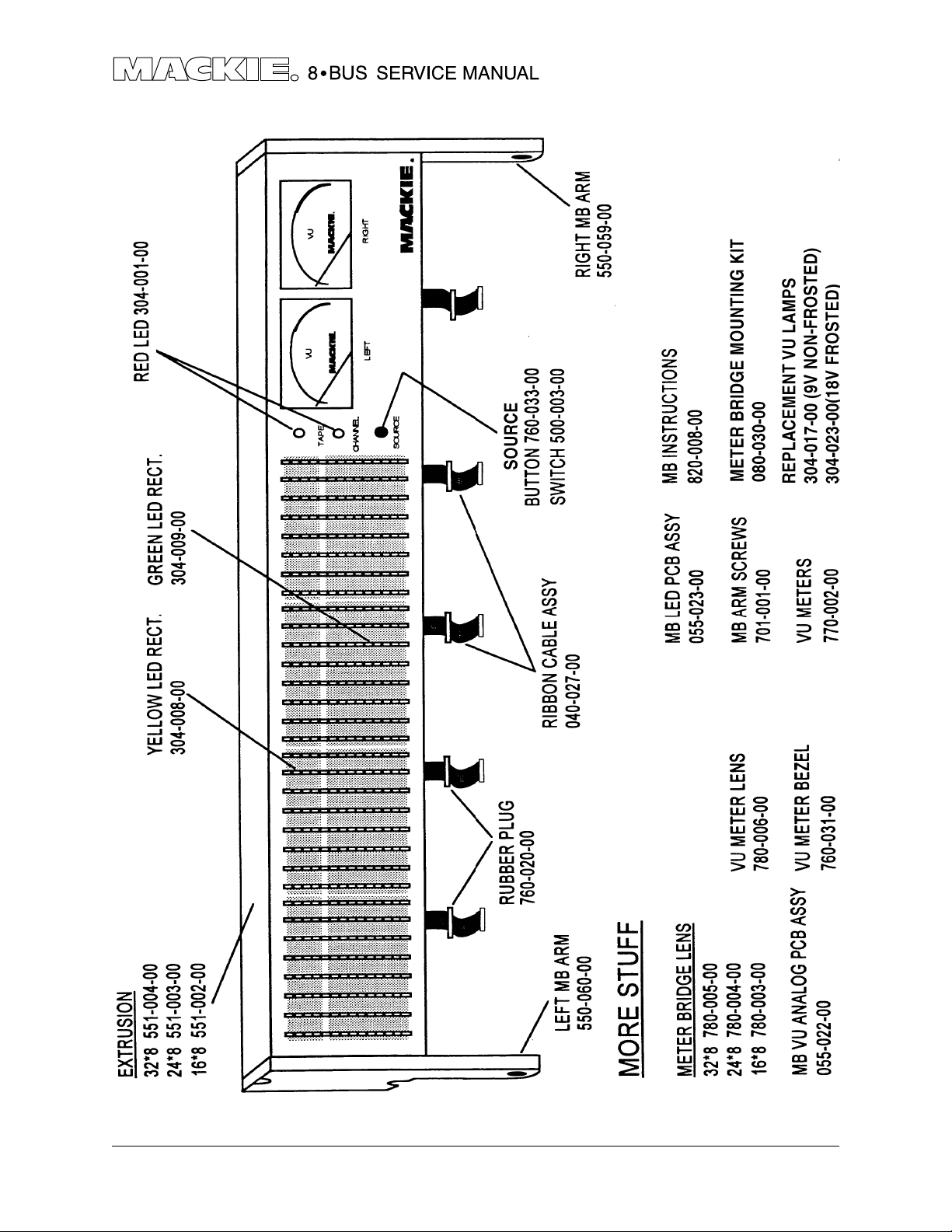
990-022-00 REV H, Analog Meter board
PART NO. DESCRIPTION VALUE REFERENCE DESIGNATORS
040-027-00 CABLE ASSY, METER BRIDGE J13
100-057-00 RESISTOR CF 2K2 5% R1 R5 R13-14
100-073-00 RESISTOR CF 10K 5% R6-7 R18-19
100-080-00 RESISTOR CF 2 0K 5% R17 R20 R22-23
100-089-00 RESISTOR CF 47K 5% R2 R12 R15-16
100-104-00 RESISTOR CF 200K 5% R3
100-109-00 RESISTOR CF 1M 5% R4
110-001-00 RESISTOR CF 10 5% R8-9
110-064-00 RESISTOR CF 4K3 5% R10-11
111-017-00 RESISTOR CF 4.7 5% R25
130-015-00 RESISTOR POT TRIM HORIZ 50KB R21 R24
211-001-00 CAPACITOR CERAMIC 0.01 10% C3-4 C8-11
211-002-00 CAPACITOR CERAMIC AXIAL 100 PF 10% C13 C15
220-001-02 CAP LYTIC RADIAL TAPE 22UF 10% C14 C16
220-010-02 CAP LYTIC RADIAL KS TAPE 22UF 10% C6-7
220-014-02 CAPACITOR LYTIC RADIAL TAPE 2.2UF 10% C1-2 C5 C12
300-002-00 DIODE 1N34A D3-10
304-001-00 DIODE LED T1 R E D D1-2
320-001-00 I.C. LINEAR NJM 4560 U2-3
325-002-00 IC, 14093 CMOS NAND GATE X4 U1
400-067-00 PIN RECEPTACLE E1-3
450-022-00 PCB, ANALOG METER BD Z1
500-003-00 SWITCH MOM TL1105/SP SPST SW 1
550-128-00 VU PLATE Z1 5
609-001-00 WIRE, 26 AWG RED 3.5 IN Z5-6
609-002-00 WIRE, 26 AWG BLK 3 IN Z4 Z10
609-003-00 WIRE, 26 AWG GRN 4 IN ST2 .25 Z7 Z9
609-004-00 WIRE, 26 AWG BLUE 4.5 IN ST2 0.25 Z8 Z11
700-011-00 SCREW, BTN HD 4-40X1/4 Z16-17 Z19-22
706-020-00 SPACER, LED .160 THRU Z2 Z12
706-030-00 STANDOFF, SWAGE 4-40 Z23-28
720-004-00 TAPE,DS,.125 X .75W, NEO Z2 9
770-002-00 METER, YS-475 Z3 Z13
780-010-00 REFLECTOR, VU METER Z14 Z18
A-15
Page 24

990-023-00 REV F, LED Meter board
PART NO. DESCRIPTION VALUE REFERENCE DESIGNATORS
040-027-00 CABLE ASSY, METER BRIDGE J12
140-051-00 RESISTOR CF 1 20 5% R101 R104-108 R201 R204-208 R301
R304-308 R401 R404-408
140-076-00 RESISTOR CF 1K3 5% R110-113 R210-213 R310-313 R410-413
140-094-00 RESISTOR CF 7K5 5% R114-115 R214-215 R314-315 R414-415
140-097-00 RESISTOR CF 10K 5% R117-122 R124-129 R217-222 R224-229
R317-322 R324-329 R417-422 R424-429
140-101-00 RESISTOR CF 15K 5% R102 R109 R202 R209 R302 R309 R402
R409
140-104-00 RESISTOR CF 20K 5% R116 R123 R216 R223 R316 R323 R416
R423
140-112-00 RESISTOR CF 3 9K 5% R103 R203 R303 R403
212-001-00 CAPACITOR CERAMIC 0.01 5% C 5 C101 C103 C112-113 C201 C203
C212-213 C301 C303 C312-313 C401
C403 C412-413
212-005-00 CAPACITOR CERAMIC 20PF 5% C114-115 C214-215 C314-315 C414-415
221-001-00 CAPACITOR LYTIC AXIAL 470UF 10% C1-2
223-001-00 CAPACITOR LYTIC SMT 2.2UF 20% C106-111 C206-211 C306-311 C406-411
223-003-00 CAPACITOR LYTIC SMT 22UF 20% C102 C104-105 C202 C204-205 C302
C304-305 C402 C404-405
304-008-00 DIODE LED RECT YEL D101-104 D113-116 D201-204 D213-216
D301-304 D313-316 D401-404 D413-416
304-009-00 DIODE LED RECT GRN D105-112 D117-124 D205-212 D217-224
D305-312 D317-324 D405-412 D417-424
311-002-00 X-SISTOR PNP IMBT4403 Q101-104 Q201-204 Q301-304 Q401-404
311-003-00 TRANSISTOR NPN 2SC4695 Q105-108 Q205-208 Q305-308 Q405-408
320-004-00 I.C. LINEAR NJM 4560 U102 U202 U302 U402
324-002-00 I.C. METER DR. BA6820F U101 U201 U301 U401
400-067-00 PIN RECEPTACLE E1-8
450-023-00 PCB, LED METER BD. Z1
706-021-00 SPACER, RUBBER LED MTR BR Z3 Z5 Z7 Z9 Z11 Z13 Z15 Z17
760-032-00 BEZEL, LED Z2 Z4 Z6 Z8 Z10 Z12 Z14 Z16
A-16
Page 25

THE MIXER FIXER • MACKIE DESIGNS SERVICE NEWSTHE MIXER FIXER • MACKIE DESIGNS SERVICE NEWS
8•BUS EQ FAILURES
Model: 8*Bus, all
Symptom: EQ failures, dead, noisy, intermittent, etc..., channel functions normally
when EQ and HPF are bypassed.
Cause: Faulty EQ module or cold solder joints on EQ module. May also be due
to a bad connection or component in the circuitry supporting the EQ
module, but more often than not it’s the module itself.
Fix: First, inspect the solder joints on the EQ daughter board and supporting
components. If problem persists, replace the EQ daughter board, part
#055-016-00.
Notes: EQ daughter board uses all surface mount components, much easier to
replace than repair.
8BUS_003 JT 10/2/95
Page 26

THE MIXER FIXER • MACKIE DESIGNS SERVICE NEWSTHE MIXER FIXER • MACKIE DESIGNS SERVICE NEWS
8•BUS METER FLICKER / CROSSTALK
Model: 8*bus, all.
Symptom: When a level is displayed on any of the bar graph meters, other meters
flicker or indicate a small level with no signal present on their associated
bus. May be intermittent.
Cause: Bad digital ground connection. Usually in the 5V cable or its connectors.
Solution: Remove the molex connectors, solder the 5V cable’s leads directly to the
PCB on both ends, and jump pins 1 and 3 of the 5 volt cable together on
the master PCB. (This is the 3 conductor cable that runs from the power
distribution PCB to the output (master) PCB.)
Notes: 5V cable part # 040-025-00. Global problems with the solo, mute, and
metering functions can also be related to this cable.
8BUS_002 JT 10/2/95
Page 27

THE MIXER FI XER. MACKIE DESIGNS SERVICE NEWS
METER BRIDGE ANALOG METER REPLACEMENT
1. Remove right end cap
IMPORTANT: Do Not remove left end cap, removing the left end cap can cause
alignment problems when re-assembling.
2. remove source select button.
3. Carefully slide out face plate.
4. Remove jumpers connecting analog meter PCB to bar graph PCB.
5. Remove rubber ring from cable.
6. Push ribbon cable through back of meter bridge housing.
7. Carefully slide out analog meter PCB.
Before installing the new analog meter PCB, affix the provided white plastic insulator to
back of the meter bridge housing so it will keep the meter terminals from shorting. Also,
apply the black foam rubber tape to the front-inside edge of the end cap so that it
presses against both the PCB and the face plate when re-assembled.
Installation is the reverse of removal except for calibration.
Mechanical Calibration (-∞dB)
Before putting on face plate, stand meter bridge in an upright position as it would be in
use and adjust each meters mechanical zero if necessary.
Electronic Calibration
The meters sensitivity trim pots are set at the factory and should not require adjustment.
However, if needed, they can be adjusted as follows:
1. Install meter bridge onto mixer with its face plate removed.
2. Check mechanical calibration.
3. Run a +4dB, 1kHz signal to the main outs, measure it with an audio analyzer or DMM
(+4dBu=1.23 VAC RMS), Do not go by the bar graphs!
4. Adjust trim pots so that meters read 0dB.
Page 28

THE MIXER FIXER • MACKIE DESIGNS SERVICE NEWSTHE MIXER FIXER • MACKIE DESIGNS SERVICE NEWS
Funny little things the 8•Bus does and what causes them.
Some miscellaneous failure modes not covered in previous Mixer Fixer notes.
Channel overload light comes on with no signal, channel passes signal normally except
for distortion with high level signals. May only happen after mixer heats up.
1. Check R_74 (pull down resistor for op-amp following fader) it probably only has 1 leg
inserted, or it may have a cap stuffed in its place.
2. If R_74 is not properly installed another 15K resistor can be installed from the back of
the PCB.
Subgroup 4 goes out when a plug is inserted into tape out 4, 12, or 20.
-Solder bridge on tape out pcb.
-Check the vias adjacent to the ribbon connectors on the tape out PCB.
Noisy Mic/Line preamp
-More often than not caused by the 4148 calmping diodes.
Mute switch pops on console with meter bridge installed.
-If the pop goes away when the meter bridge is disconnected the problem is a solder
bridge on the bargraph meter PCB causing DC to leak into the channel via the meter
feed (same path as the direct out).
Page 29

THE MIXER FIXER • MACKIE DESIGNS SERVICE NEWSTHE MIXER FIXER • MACKIE DESIGNS SERVICE NEWS
32•8 NOT POWERING UP CORRECTLY
Model: 8•Bus Power Supply and console, usually 32•8 with meter bridge.
Serial #: Power Supply serial G27894 - G29655.
Symptom: All overload lights come on and stay on upon power up. If the Power
Supply is switched off for a second then back on the console functions
normally.
Cause: New revision Power Supply’s current limiting is more sensitive. The inrush
of current drawn by a cold power up can cause it to latch the +18V rail
at or near ground.
Solution: Remove R39 and R44.
Notes: R34, R44 = 6.81k, changed to 10K on units with serial above G29655.
R39, R44
8BUS_004 JT 5/3/96
Page 30

THE MIXER FIXER • MACKIE DESIGNSTHE MIXER FIXER • MACKIE DESIGNS
SERVICE NEWSSERVICE NEWS
8•BUS REMOTE TALKBACK MODIFICATION
The diagram below illustrates the easiest way to add remote controllable relay to the
studio/phones talkback switch without interfering with the original switch. This
modification can be performed entirely from the back of the master PCB and does not
require removing the PCB.
Notes: Simply paralleling a switch across the back of the existing switch will not
work because the existing switch holds the T/B-to-studio/phones input at
ground until pressed.
Page 31

The console’s +12VDC lamp supply can be used to drive the relay.
Section of master PCB
x
Cut trace here
To control voltage
TBMOD.DOC JT 2/21/96
 Loading...