


Mach 1 Acoustics 1642-VLZPRO Owners manual
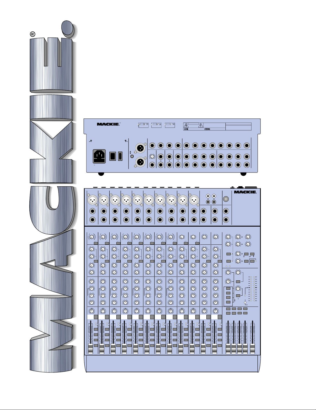
1642-VLZ PRO
16-CHANNEL
MIC/LINE MIXER
OWNER’S MANUAL
1642-VLZPRO
16-CHANNEL MIC /L INE MIXER
TM
WITH PREMIUM XDR
MIC PREAMPLIFIERS
CONCEIVED, DESIGNED, AND MANUFACTURED BY MACKIE DESIGNS INC •
WOODINVILLE WA • 98072 • USA • MADE IN USA • PATENTS PENDING •
COPYRIGHT ©1998• THE FOLLOWING ARE REGISTERED TRADEMARKS OF
MACKIE DESIGN INC.: "MACKIE", "XDR", AND THE "RUNNING MAN" FIGURE •
CAUTION:
TO REDUCE THE RISK OF
FIRE REPLACE WITH SAME
TYPE FUSE AND RATING
1A/250V SLO-BLO
MIC
2
M
I
C
R
P
D
R
X
E
LINE IN
BAL
BAL
UN
UN
-
-
BAL
BAL
INSERT
TRIM
d
B
0
V
1
-
G
A
C
I
N
I
1
2
M
U
060
+15dB-45dB
LOW CUT
75 Hz
18dB/OCT
AUX
U
1
OO
+15
U
2
OO
+15
PRE
U
3
OO
+15
U
4
OO
+15
EQ
U
HI
HI
12k
12k
+15-15
U
MID
+15
15
-
800
FREQ
2k200
8k100
U
LOW
80Hz
+15-15
PAN
LR
23
OL
dB
10
5
20
-
U
SOLO
5
10
-
2
-
2
1
20
3
-
4
-
4
30
40
50
L/R
60
OO
2
POWER
U
AUX
1
2
3
4
EQ
dB
10
5
U
5
10
20
30
40
50
60
OO
1
2
3
4
EQ
dB
10
5
U
5
10
20
30
40
50
60
U
+15dB-45dB
LOW CUT
18dB/OCT
AUX
MUTE
OO
-
120 VAC 50/60 Hz 40W
MIC
1
M
I
C
R
P
D
R
X
E
LINE IN
INSERT
TRIM
d
B
0
V
1
-
G
A
C
I
N
I
M
060
75 Hz
U
OO
+15
U
OO
+15
PRE
U
OO
+15
U
OO
+15
U
+15-15
U
+15
15
800
2k200
8k100
U
+15-15
PAN
LR
1
-
SOLO
1
3
L/R
REC1REC
MID
FREQ
LOW
80Hz
OL
20
ON
MIC
X
LINE IN
INSERT
1
-
I
M
060
+15dB-45dB
LOW CUT
75 Hz
18dB/OCT
OO
OO
OO
OO
15
-
LR
MUTEMUTE
STEREO
MONO PLUG MONO PLUG
PLUG
TIP OUT TO EFFECTS DEVICE
RING RETURN FROM EFFECTS
FOR USE AS AN EFFECTS LOOP
(TIP = SEND, RING = RETURN)
INTERRUPTION TO MASTER
MAIN OUTS
L
ON
+4
MIC
PHANTOM
MIC
3
4
M
M
I
I
C
C
R
R
P
P
D
D
R
R
X
E
E
MONO
(BAL/UNBAL)
R
OO
LEVEL
MIC
MIC
5
6
M
M
I
I
C
C
R
R
P
P
D
D
R
R
X
X
E
INSERT ALL THE WAY IN TO
THE "SECOND CLICK"
DIRECT OUT WITH SIGNAL
U
+15
E
MAIN
(BAL/UNBAL)
MIC
M
R
D
X
DIRECT OUT WITH NO SIGNAL
INTERRUPTION TO MASTER
AUX SENDS
(BAL/UNBAL)
L
R
7
I
C
P
R
E
INSERT ONLY INTO THE
"FIRST CLICK"
MAIN
INSERT
MIC
X
R
8
M
I
C
R
P
D
R
CAUTION
WARNING:
TO REDUCE THE RISK OF FIRE OR ELECTRIC SHOCK, DO NOT
EXPOSE THIS EQUIPMENT TO RAIN OR MOISTURE. DO NOT REMOVE COVER.
RISK OF ELECTRIC SHOCK
REPLACE WITH THE SAME TYPE FUSE AND RATING.
DISCONNECT SUPPLY CORD BEFORE CHANGING FUSE
8
4321
C-R OUTS
(BAL/UNBAL)
11
LRL
52637
MIC
9-10
M
I
C
R
P
D
R
X
E
E
NO USER SERVICEABLE PARTS INSIDE. REFER SERVICING TO QUALIFIED PERSONNEL.
DO NOT OPEN
AVIS:
RISQUE DE CHOC ELECTRIQUE — NE PAS OUVRIR
UTILISE UN FUSIBLE DE RECHANGE DE MÊME TYPE.
DEBRANCHER AVANT DE REMPLACER LE FUSIBLE
XDRTM EXTENDED DYNAMIC RANGE MIC PREAMPLIFIERS ARE PROPRIETARY TO MACKIE DESIGNS, INC.
7654321
SUB OUTS
(BAL/UNBAL)
DIRECT OUTS
4 234
8
TAPEINTAPE
MIC
11-12
M
I
C
R
P
D
R
X
E
OUT
LEFT
RIGHT
LINE IN
LINE IN
LINE IN
LINE IN
LINE IN
LINE IN 9
LINE IN 11 LINE IN LINE IN
BAL
BAL
BAL
BAL
UN
UN
-
BAL
INSERT
TRIM
d
B
d
0
0
V
1
-
G
G
A
C
C
I
N
I
3
M
U
060
+15dB-45dB
LOW CUT
75 Hz
18dB/OCT
AUX
U
U
1
OO
+15
U
U
2
OO
+15
PRE
PRE
U
U
3
OO
+15
U
U
4
OO
+15
EQ
U
U
HI
12k
+15-15
U
U
MID
+15
15
-
800
800
FREQ
2k200
8k100
U
U
LOW
80Hz
+15-15
PAN
LR
4
MUTE
OL
dB
10
5
20
-
U
SOLO
5
10
-
2
1
20
3
-
4
30
40
50
L/R
60
OO
TRACK
1
UN
-
-
BAL
BAL
INSERT
INSERT
TRIM
TRIM
B
d
B
d
0
0
V
V
1
1
-
-
G
A
I
N
4
+15
+15
+15
+15
HI
12k
+15-15
MID
+15
FREQ
2k200
8k100
LOW
80Hz
+15-15
PAN
OL
20
-
SOLO
-
2
1
3
-
4
L/R
TRACK
2
G
A
C
C
I
N
I
I
5
M
M
U
U
060
060
+15dB-45dB
+15dB-45dB
LOW CUT
LOW CUT
75 Hz
75 Hz
18dB/OCT
18dB/OCT
AUX
AUX
U
U
1
1
OO
OO
+15
U
U
2
2
OO
OO
+15
PRE
PRE
U
U
3
3
OO
OO
+15
U
U
4
4
OO
OO
+15
EQ
EQ
U
U
HI
12k
+15-15
U
U
MID
+15
15
15
-
-
800
800
FREQ
2k200
8k100
U
U
LOW
80Hz
+15-15
PAN
LR
LR
5
MUTE6MUTE7MUTE8MUTE
OL
dB
dB
10
10
5
5
20
-
U
U
SOLO
5
5
10
10
-
2
1
20
20
3
-
4
30
30
40
40
50
50
L/R
60
60
OO
OO
TRACK
3
BAL
UN
UN
-
-
BAL
BAL
INSERT
INSERT
TRIM
TRIM
B
d
d
B
0
1
2
3
4
EQ
dB
10
5
U
5
10
20
30
40
50
60
U
+15dB-45dB
LOW CUT
18dB/OCT
AUX
OO
1
-
C
I
M
060
75 Hz
OO
OO
OO
OO
15
-
LR
0
V
1
-
G
G
A
C
I
N
I
7
M
U
060
+15dB-45dB
LOW CUT
75 Hz
18dB/OCT
AUX
U
U
1
OO
+15
U
U
2
OO
+15
PRE
PRE
U
U
3
OO
+15
U
U
4
OO
+15
EQ
U
U
HI
12k
+15-15
U
U
MID
+15
15
-
800
800
FREQ
2k200
8k100
U
U
LOW
80Hz
+15-15
PAN
LR
OL
dB
10
5
20
-
U
SOLO
5
10
-
2
1
20
3
-
4
30
40
50
L/R
60
OO
TRACK
5
V
A
I
N
6
+15
+15
+15
+15
HI
12k
+15-15
MID
+15
FREQ
2k200
8k100
LOW
80Hz
+15-15
PAN
OL
20
-
SOLO
-
2
1
3
-
4
L/R
TRACK
4
BAL
BAL
UN
UN
-
-
L
L
BAL
BAL
LINE IN 10
LINE IN 12
R
R
TRIM
TRIM
B
V
G
A
A
C
I
I
N
N
I
8
+15
+15
+15
+15
HI
12k
+15-15
MID
+15
FREQ
2k200
8k100
LOW
80Hz
+15-15
PAN
OL
20
-
SOLO
-
2
1
3
-
4
L/R
TRACK
6
I
9
M
M
10
060
060
LOW CUT
LOW CUT
75 Hz
75 Hz
18dB/OCT
18dB/OCT
AUX
AUX
U
1
1
OO
OO
+15
U
2
2
OO
OO
+15
PRE
U
3
3
OO
OO
+15
U
4
4
OO
OO
+15
EQ
EQ
U
HI
12k
+15-15
U
HI
MID
3K
+15
15
15
-
-
U
LOW
MID
800Hz
+15-15
U
LOW
80Hz
+15-15
PAN
LR
9-10
11- 12
MUTE
MUTE
OL
dB
dB
10
10
5
5
20
-
U
U
SOLO
5
5
10
10
-
2
1
20
20
3
-
4
30
30
40
40
50
50
L/R
60
60
OO
OO
TRACK
7
MONOMONOMONO
BAL
13
UN
-
LEFT
BAL
BAL/
UNBAL
14
RIGHT
TRIM
TRIM
U
G
A
C
I
N
13
11
12
14
+20
-20
AUX
U
U
1
OO
+15
+15
U
U
2
OO
+15
+15
PRE
PRE
U
U
3
OO
+15
+15
U
U
4
OO
+15
+15
EQ
U
U
U
U
U
LR
HI
HI
12k
12k
+15-15
+15-15
U
HI
HI
MID
MID
3K
3K
+15
15
+15
-
U
LOW
LOW
MID
MID
800Hz
800Hz
+15
15
+15-15
-
U
LOW
LOW
80Hz
80Hz
+15-15
+15-15
PAN PAN
PAN
LR
13-14
MUTE
OL
OL
dB
10
5
20
20
-
-
U
SOLO
SOLO
5
10
-
2
-
2
1
1
20
3
3
-
4
-
4
30
40
50
L/R
L/R
60
OO
TRACK8EFXAEFX
AUX
1
2
3
4
EQ
15-1 6
MUTE
dB
10
5
U
5
10
20
30
40
50
60
OO
(BAL/UNBAL)
U
-20
U
O
O
U
OO
PRE
U
OO
U
OO
U
U
15
-
U
15
-
U
LR
RIGHT
+20
+15
+15
+15
+15
+15-15
+15
+15
+15-15
LEFT
MONO
15
LEFT
BAL/
UNBAL
16
RIGHT
TRIM
15
16
HI
12k
HI
MID
3K
LOW
MID
800Hz
LOW
80Hz
OL
20
-
SOLO
-
2
1
3
-
4
L/R
B
SERIAL NUMBER MANUFACTURING DATE
AUX RETURN
(BAL/UNBAL)
LRL
R
LAMP
WITH PREMIUM XDR
12V
0.5A
PHONES
A
B
AUX SEND
U
1
1
OO
+10
U
2
2
OO
+10
3
1
SOLO
4
2
SOLO
PWR
PHAN
OO
MAX
OO
TAPE IN
PHONES
TAPE TO
MAX
OO
MAIN MIX
CONTROL ROOM
TAPE
SOLO
SUBS 1–2
MODE
SUBS 3
–
4
NORMAL
LEVEL SET
MAIN MIX
CR SOURCE
LEFT
LEFT
RIGHT
RIGHT
1526374
dB
10
5
U
5
10
20
30
40
50
60
OO
LRL
(MONO)(MONO)(MONO)(MONO)
R
1642-VL ZPRO
16-CHANNEL MIC / LINE MIXER
TM
MIC PREAMPLIFIERS
EFFECTS TO MONITORS
U
U
1
OO
OO
+20
+15
U
U
2
OO
OO
+15
+20
U
ASSIGN OPTIONS
MAIN MIX
OO
+20
TO SUBS
U
C-R / PHNS
OO
+20
ONLY
STEREO AUX RETURN
U
+20
OO
MAX
LEVEL
SET
(AFL)
(PFL)
RUDE SOLO LIGHT
LEFT
LEFT
RIGHT
RIGHT
8
dB
10
5
U
5
10
20
30
40
50
60
1
3–4
RETURNS
SOLO
LEFT RIGHT
0 dB=0 dBu
MAIN
MIX
OO
TO AUX
SEND 1
TO AUX
SEND 2
–
2
28
10
7
4
2
0
2
4
7
10
20
30
CAUTION AVIS
RISK OF ELECTRIC
DO NOT OPEN
RISQUE DE
CAUTION: TO REDUCE THE RISK OF ELECTRIC SHOCK
DO NOT REMOVE COVER (OR BACK)
NO USER-SERVICEABLE PARTS INSIDE
REFER SERVICING TO QUALIFIED PERSONNEL
ATTENTION: POUR EVITER LES RISQUES DE CHOC
ELECTRIQUE, NE PAS ENLEVER LE COUVERCLE. AUCUN
ENTRETIEN DE PIECES INTERIEURES PAR L'USAGER. CONFIER
L'ENTRETIEN AU PERSONNEL QUALIFIE.
AVIS: POUR EVITER LES RISQUES D'INCENDIE OU
D'ELECTROCUTION, N'EXPOSEZ PAS CET ARTICLE
The lightning flash with arrowhead symbol within an equilateral
triangle is intended to alert the user to the presence of uninsulated
"dangerous voltage" within the product's enclosure, that may be
of sufficient magnitude to constitute a risk of electric shock to persons.
Le symbole éclair avec point de flèche à l'intérieur d'un triangle
équilatéral est utilisé pour alerter l'utilisateur de la présence à
l'intérieur du coffret de "voltage dangereux" non isolé d'ampleur
suffisante pour constituer un risque d'éléctrocution.
The exclamation point within an equilateral triangle is intended to
alert the user of the presence of important operating and maintenance
(servicing) instructions in the literature accompanying the appliance.
Le point d'exclamation à l'intérieur d'un triangle équilatéral est
employé pour alerter les utilisateurs de la présence d'instructions
importantes pour le fonctionnement et l'entretien (service) dans le
livret d'instruction accompagnant l'appareil.
CHOC
NE PAS OUVRIR
A LA PLUIE OU A L'HUMIDITE
SHOCK
ELECTRIQUE
SAFETY INSTRUCTIONS
1. Read Instructions — All the safety and operation
instructions should be read before this Mackie product is
operated.
2. Retain Instructions — The safety and operating
instructions should be kept for future reference.
3. Heed Warnings — All warnings on this Mackie product and
in these operating instructions should be followed.
4. Follow Instructions — All operating and other instructions
should be followed.
5. Water and Moisture — This Mackie product should not be
used near water – for example, near a bathtub, washbowl,
kitchen sink, laundry tub, in a wet basement, near a
swimming pool, swamp or salivating St. Bernard dog, etc.
6. Heat — This Mackie product should be situated away
from heat sources such as radiators, or other devices which
produce heat.
7. Power Sources — This Mackie product should be
connected to a power supply only of the type described in
these operation instructions or as marked on this Mackie
product.
8. Power Cord Protection — Power supply
cords should be routed so that they are not
likely to be walked upon or pinched by items
placed upon or against them, paying
particular attention to cords at plugs,
convenience receptacles, and the point where
they exit this Mackie product.
9. Object and Liquid Entry — Care should be
taken so that objects do not fall into and
liquids are not spilled into the inside of this
Mackie product.
Duration Per Day Sound Level dBA, Typical
In Hours Slow Response Example
1.5 102
0.5 110
0.25 or less 115 Loudest parts at a rock concert
10. Damage Requiring Service — This Mackie product
should be serviced only by qualified service personnel when:
A. The power-supply cord or the plug has been
damaged; or
B. Objects have fallen, or liquid has spilled into
this Mackie product; or
C. This Mackie product has been exposed to rain;
or
D. This Mackie product does not appear to operate
normally or exhibits a marked change in
performance; or
E. This Mackie product has been dropped, or its
chassis damaged.
11. Servicing — The user should not attempt to service this
Mackie product beyond those means described in this
operating manual. All other servicing should be referred to the
Mackie Service Department.
12. To prevent electric shock, do not use this polarized plug
with an extension cord, receptacle or other outlet unless the
blades can be fully inserted to prevent blade exposure.
Pour préevenir les chocs électriques ne pas utiliser cette fiche
polariseé avec un prolongateur, un prise de courant ou une
autre sortie de courant, sauf si les lames peuvent être insérées
à fond sans laisser aucune pariie à découvert.
13. Grounding or Polarization — Precautions should be
taken so that the grounding or polarization means of this
Mackie product is not defeated.
14. This apparatus does not exceed the Class A/Class B
(whichever is applicable) limits for radio noise emissions from
digital apparatus as set out in the radio interference
regulations of the Canadian Department of Communications.
ATTENTION —Le présent appareil numérique n’émet pas de
bruits radioélectriques dépassant las limites applicables aux
appareils numériques de class A/de class B (selon le cas)
prescrites dans le règlement sur le brouillage radioélectrique
édicté par les ministere des communications du Canada.
15. To prevent hazard or damage, ensure that only
microphone cables and microphones designed to IEC 268-15A
are connected.
8 90 Duo in small club
692
4 95 Subway Train
397
2 100 Very loud classical music
1 105 Patrice screaming at Ron about deadlines
WARNING — To reduce the risk of fire or electric shock,
do not expose this appliance to rain or moisture.
READ THIS P AGE!!!
We realize that you must have a powerful
hankerin’ to try out your new 1642-VLZ
Or you might be one of those people who
never reads manuals. Either way, all we ask
is that you read this page NOW, and the rest
can wait until you’re good and ready. But do
read it — you’ll be glad you did.
PRO.
LEVEL-SETTING PROCEDURE
Message to seasoned pros: do NOT set levels
using the old “Turn the trim up until the clip
light comes on, then back off a hair” trick. When a
Mackie Designs mixer clip light comes on, you
really are about to clip.
This procedure really works — it assures
low noise and high headroom. Please read on.
It’s not even necessary to hear what you’re doing to set optimal levels. But if you’d like to: Plug
headphones into the
then set the
ter of the way up.
The following steps must be performed one
channel at a time:
1. Turn the
controls fully down.
2. Be sure the
assignment switches are all disengaged.
3. Set the
4. Connect the signal source to the
5. Engage (push in) the channel’s
6. Push in the
7. Play something into the selected input, at
8. Adjust the
9. If you’d like to apply some
10. Disengage that channel’s
11. Repeat for each channel.
EQ
LINE
channel input.
switch.
section (
LEVEL SET
real-world levels.
display on the meter stays around “0.”
(Only the left meter is active in the
Level-Setting Procedure.)
now and return to the previous step.
PHONES
PHONES
TRIM, AUX
LEVEL SET (PFL)
knob about one-quar-
1–2, 3–4
knobs at the center detents.
MODE
LED will light.
TRIM
control so that the
output jack,
send and fader
and
L/R
channel
MIC
SOLO
switch in the output
mode) — the
EQ
, do so
SOLO
switch.
or
Other Nuggets of Wisdom
For optimum sonic performance, the channel
faders and the
near the “
Always turn down the
CONTROL ROOM
making connections to your 1642-VLZ
If you shut down your equipment, turn off
your amplifiers first. When powering up, turn
on your amplifiers last.
Save the shipping box! You may need it
someday, and you don’t want to have to pay for
another one.
MAIN MIX
U
” (unity gain) markings.
fader should be set
MAIN MIX
and
PHONES
fader and
knobs before
PRO.
INSTANT MIXING
Here’s how to get going
right away, assuming you own
a microphone and a keyboard:
1. Plug your microphone into Channel 1’s
MIC
input.
2. Turn on the 1642-VLZ
3. Perform the Level-Setting Procedure .
4. Connect cords from the
to your amplifier .
5. Hook up speakers to the amp and turn it on.
6. Set channel 1’s fader to the “U” mark.
7. Engage (push in) Channel 1’s
8. Set the
the way up.
9. Sing like a canary!
10. Plug your keyboard into channels 3 and 4.
11. Turn channel 3’ s
channel 4’s
12. Set those faders to the “U” mark.
13.
Perform the Level-Setting Procedure .
14.
Engage the
15. Play like a madman and sing like a canary!
It’s your first mix!
MAIN MIX
PAN
L/R
PRO.
MAIN OUT
fader one-quarter of
PAN
knob fully left and
knob fully right.
switch on these channels.
L/R
jacks
switch.
Please write your serial number here for
future reference (i.e. insurance claims,
tech support, return authorization, etc.):
Purchased at:
Part No. 820-200-00 Rev. A 08/99
©1999 Mackie Designs Inc. All Rights Reserved.
Printed in the U.S.A.
Date of purchase:
3
INTRODUCTION
Thank you for choosing a Mackie Designs
professional compact mixer . The 1642-VLZ PRO
is equipped with our new precision-engineered
TM
Extended Dynamic Range premium mic
XDR
preamps featuring:
• Full gain range from 0 to 60dB
• +22 dBu line signal handling capability
• 130 dB dynamic range
• Distortion less than 0.0007%, 20Hz to 20kHz
• Bullet-proof RF rejection using DC pulse
transformer circuitry
• Made in Woodinville, Washington, USA
Now that you have your 1642-VLZ PRO, find
out how to get the most from it. That’s where
this manual comes in.
HOW TO USE THIS MANUAL
Since many of you folks will want to hook up
your 1642-VLZ
you will encounter after the table of contents are
the ever popular hookup diagrams. These show
typical mixer setups for Record/Mixdown, Video,
Stereo PA and a fixed installation. After this section is a detailed tour of the entire mixer.
Every feature of the 1642-VLZ
described “geographically;” in other words, in
order of where it is physically placed on the
mixer’s top or r ear panel. These descriptions ar e
divided into the first three manual chapters, just
as your mixer is organized into three distinct
zones:
1. PATCHBAY: The zillion jacks along on the
top edge and the rear panel
2. CHANNEL STRIP: The channel strips on
the left.
3. OUTPUT SECTION: The output section on
the right.
MIC
MIC
1
2
M
M
I
I
C
C
R
R
P
P
D
D
R
R
X
X
E
E
LINE IN
LINE IN
BAL
BAL
UN
UN
-
-
BAL
BAL
INSERT
INSERT
TRIM
TRIM
B
B
d
d
V
V
0
0
1
1
-
-
G
G
A
A
C
C
I
I
I
I
N
N
1
2
M
M
U
U
060
060
+15dB-45dB
+15dB-45dB
LOW CUT
LOW CUT
75 Hz
75 Hz
18dB/OCT
18dB/OCT
AUX
AUX
U
U
1
1
1
OO
OO
+15
+15
U
U
2
2
2
OO
OO
+15
+15
PRE
PRE
U
U
3
3
3
OO
OO
+15
+15
U
U
4
4
4
OO
OO
+15
+15
EQ
EQ
EQ
U
U
HI
HI
12k
12k
CHANNEL STRIPS
+15-15
+15-15
U
U
HI
HI
MID
MID
3K
3K
+15
+15
15
15
-
-
800
800
FREQ
FREQ
2k200
2k200
8k100
8k100
U
U
LOW
LOW
80Hz
80Hz
+15-15
+15-15
PAN
PAN
LR
LR
1
23
MUTE
OL
OL
dB
dB
dB
10
10
10
5
5
5
20
20
-
-
U
U
U
SOLO
SOLO
5
5
5
10
10
10
-
2
-
2
1
1
20
20
20
3
3
-
4
-
4
30
30
30
40
40
40
50
50
50
L/R
L/R
60
60
60
OO
OO
PRO immediately, the first pages
MIC
MIC
MIC
MIC
MIC
MIC
3
M
I
C
R
P
D
R
X
E
LINE IN
BAL
UN
BAL
INSERT
TRIM
B
d
V
0
1
-
G
A
C
I
I
N
M
U
060
+15dB-45dB
LOW CUT
75 Hz
18dB/OCT
AUX
U
OO
+15
U
OO
+15
PRE
U
OO
+15
U
OO
+15
U
HI
12k
+15-15
U
HI
MID
3K
+15
15
-
800
FREQ
2k200
8k100
U
LOW
80Hz
+15-15
PAN
LR
MUTEMUTE
OL
20
-
SOLO
-
2
1
3
-
4
L/R
OO
1
4
5
M
M
I
I
C
C
R
R
R
P
P
D
D
D
R
R
X
X
X
E
E
LINE IN
LINE IN
LINE IN
BAL
BAL
UN
UN
-
-
-
BAL
BAL
INSERT
INSERT
INSERT
PATCHBAY
TRIM
TRIM
B
B
d
d
d
V
V
0
0
0
1
1
1
-
-
-
G
G
G
A
A
C
C
C
I
I
I
I
I
N
N
3
4
5
M
M
M
U
U
U
060
060
060
+15dB-45dB
+15dB-45dB
+15dB-45dB
LOW CUT
LOW CUT
LOW CUT
75 Hz
75 Hz
75 Hz
18dB/OCT
18dB/OCT
18dB/OCT
AUX
AUX
AUX
U
U
U
1
1
1
OO
OO
OO
+15
+15
U
U
U
2
2
2
OO
OO
OO
+15
+15
PRE
PRE
PRE
U
U
U
3
3
3
OO
OO
OO
+15
+15
U
U
U
4
4
4
OO
OO
OO
+15
+15
EQ
EQ
EQ
U
U
U
HI
HI
12k
12k
+15-15
+15-15
U
U
U
HI
HI
MID
MID
3K
3K
+15
+15
15
15
15
-
-
-
800
800
800
FREQ
FREQ
2k200
2k200
8k100
8k100
U
U
U
LOW
LOW
80Hz
80Hz
+15-15
+15-15
PAN
PAN
LR
LR
LR
4
5
MUTE
MUTE6MUTE7MUTE8MUTE
OL
OL
dB
dB
dB
10
10
10
5
5
5
20
20
-
-
U
U
U
SOLO
SOLO
5
5
5
10
10
10
-
2
-
2
1
1
20
20
20
3
3
-
4
-
4
30
30
30
40
40
40
50
50
50
L/R
L/R
60
60
60
OO
OO
OO
6
M
I
C
P
R
E
TRIM
B
V
A
I
N
+15
+15
+15
+15
+15-15
+15
2k200
8k100
+15-15
SOLO
MIC
7
8
9-10
M
M
M
I
I
I
C
C
C
R
R
R
P
P
P
D
D
D
R
R
R
X
X
X
E
E
E
LINE IN
LINE IN
LINE IN 9
BAL
UN
-
BAL
INSERT
1
-
C
I
6
M
U
060
+15dB-45dB
LOW CUT
75 Hz
18dB/OCT
AUX
1
OO
2
OO
3
OO
4
OO
EQ
HI
12k
HI
MID
3K
15
-
FREQ
LOW
80Hz
PAN
LR
OL
dB
10
5
20
-
U
5
10
-
2
1
20
3
-
4
30
40
50
L/R
60
OO
BAL
BAL
BAL
UN
UN
UN
-
-
-
L
BAL
BAL
BAL
INSERT
LINE IN 10
R
TRIM
TRIM
TRIM
B
B
B
d
d
d
V
V
V
0
0
0
1
1
-
-
G
G
G
A
A
A
C
C
I
I
I
I
I
N
N
N
7
8
9
M
M
U
U
10
060
060
+15dB-45dB
+15dB-45dB
LOW CUT
LOW CUT
75 Hz
75 Hz
18dB/OCT
18dB/OCT
AUX
AUX
U
U
U
1
1
OO
OO
+15
+15
+15
U
U
U
2
2
OO
OO
+15
+15
+15
PRE
PRE
PRE
U
U
U
3
3
OO
OO
+15
+15
+15
U
U
U
4
4
OO
OO
+15
+15
+15
EQ
EQ
U
U
U
HI
HI
HI
12k
12k
12k
+15-15
+15-15
+15-15
U
U
U
HI
HI
HI
MID
MID
MID
3K
3K
3K
+15
+15
+15
15
15
-
-
800
800
U
LOW
FREQ
FREQ
2k200
2k200
MID
800Hz
+15-15
8k100
8k100
U
U
U
LOW
LOW
LOW
80Hz
80Hz
80Hz
+15-15
+15-15
+15-15
PAN
PAN
PAN
LR
LR
9-10
MUTE
OL
OL
OL
dB
dB
10
10
5
5
20
20
20
-
-
-
U
U
SOLO
SOLO
SOLO
5
5
10
10
-
2
-
2
-
2
1
1
1
20
20
3
3
3
-
4
-
4
-
4
30
30
40
40
50
50
L/R
L/R
L/R
60
60
OO
OO
TRACK7TRACK6TRACK5TRACK4TRACK3TRACK2TRACK
PRO will be
TAPEINTAPE
MIC
11-12
M
I
C
R
P
D
R
X
E
LEFT
RIGHT
LINE IN 11 LINE IN LINE IN
MONO
BAL
UN
-
L
LEFT
BAL
BAL/
LINE IN 12
UNBAL
R
RIGHT
TRIM
TRIM
B
d
V
0
1
-
U
G
A
C
I
I
N
11
M
U
12
060
+20
-20
+15dB-45dB
LOW CUT
75 Hz
18dB/OCT
AUX
AUX
U
U
1
1
OO
OO
+15
+15
U
U
2
2
OO
OO
+15
+15
PRE
PRE
U
U
3
3
OO
OO
+15
+15
U
U
4
414
OO
OO
+15
+15
EQ
EQ
U
U
HI
12k
+15-15
+15-15
U
U
HI
MID
3K
+15
15
15
+15
-
-
U
U
LOW
MID
800Hz
800Hz
+15
15
+15-15
-
U
U
LOW
80Hz
+15-15
+15-15
PAN PAN
PAN
LR
LR
11-12
13-14
MUTE
MUTE
OL
OL
dB
dB
10
10
5
5
20
-
-
U
U
SOLO
SOLO
5
5
10
10
-
2
1
1
20
20
3
3
-
4
30
30
40
40
50
50
L/R
L/R
60
60
OO
OO
TRACK8EFXAEFX
OUT
LAMP
1642-VLZ PRO
LEFT
16-CHANNEL MIC/ LINE MIXER
TM
WITH PREMIUM XDR
MIC PREAMPLIFIERS
12V
0.5A
RIGHT
PHONES
MONO
15
13
A
LEFT
BAL/
UNBAL
14
16
B
RIGHT
AUX SEND
TRIM
EFFECTS TO MONITORS
U
U
U
U
15
13
16
14
1
+20
-20
2
AUX
U
O
O
+15
U
2
OO
+15
PRE
U
3
OO
+15
U
OO
+15
EQ
U
HI
12kHI12k
+15-15
U
HI
HI
MID
MID
3K
3K
15
+15
-
U
LOW
LOW
MID
MID
800Hz
+15
15
-
U
LOW
LOW
80Hz
80Hz
+15-15
LR
15-16
MUTE
OL
dB
10
5
20
20
-
U
SOLO
5
10
-
2
-
2
1
20
3
-
4
-
4
30
40
50
L/R
60
OO
B
1
OO
+10
U
2
OO
+10
1
3
SOLO
4
2
SOLO
PWR
PHAN
MAX
OO
PHONES
OUTPUT
MAX
OO
CONTROL ROOM
TAPE
SECTION
SUBS 1–2
–
4
SUBS 3
MAIN MIX
SOURCE
LEFT
LEFT
RIGHT
RIGHT
1526374
dB
10
5
U
5
10
20
30
40
50
60
OO
OO
+20
U
OO
+20
U
OO
+20
U
OO
+20
STEREO AUX RETURN
U
OO
+20
TAPE IN
TAPE TO
MAIN MIX
OO
MAX
SOLO
MODE
NORMAL
LEVEL SET
LEFT
RIGHT
TO AUX
1
OO
+15
U
TO AUX
2
OO
+15
ASSIGN OPTIONS
–
1
MAIN MIX
3
–
TO SUBS
C-R / PHNS
RETURNS
ONLY
SOLO
LEFT RIGHT
0 dB=0 dBu
LEVEL
SET
(AFL)
(PFL)
RUDE SOLO LIGHT
LEFT
RIGHT
MAIN
MIX
8
dB
10
5
U
5
10
20
30
40
50
60
OO
Whenever a specific 1642-VLZ
PRO component is mentioned, it’ll be in all capital letters
sans-serif type. That can help you find references to specific controls much faster, without
slowing you down as you read normally. For example: The quick brown fader jumped over the
RUDE SOLO LIGHT
.
Throughout these chapters you’ll find illustrations, with each feature numbered. If you’re
curious about a feature, simply locate it on the
appropriate illustration, note the number attached to it, and find that number in the nearby
paragraphs or refer to the table of contents.
Y ou’ll also find cross-references to these numbered features within a paragraph. For instance, if
you see “To wire your own cables:
,” simply find
that number in the manual and you’ve found your
answer . (These are not page numbers.)
You’ll also notice feature numbers just float-
ing in space, like this
. These numbers
direct you to relevant information.
This icon marks information
that is critically important or
unique to the 1642-VLZ
For your own good, read them
and remember them. They will
be on the final test.
This icon will lead you to indepth explanations of features
and practical tips. While not
mandatory, they’ll have some
valuable information.
A PLUG FOR THE CONNECTORS SECTION
The Appendix gives details about connectors: XLR connectors, balanced connectors,
unbalanced connectors and special hybrid
connectors.
RACK MOUNTING
Optional rack ears are available which allow
the 1642-VLZ PRO to be fitted in a standard 19"
SEND 1
rack. This will take up a height of 12 rack
SEND 2
spaces (including enough room to make the
2
4
connections). Contact your Mackie dealer for
28
more details.
10
7
4
2
0
2
4
7
10
20
30
PRO.
4

CONTENTS
LEVEL-SETTING PROCEDURE.................................... 3
INSTANT MIXING.................................................... 3
HOOKUP DIAGRAMS .............................................. 6
PA TCHBAY DESCRIPTION ......................................... 10
E-Z INTERFACING......................................... 10
MIC/LINE INPUT FLEXIBILITY..........................10
MIC INPUTS ................................................... 10
PHANTOM POWER DISCUSSION................... 10
LINE INPUTS .................................................. 11
TRIM ............................................................. 11
INSERT........................................................... 11
DIRECT OUT ................................................... 12
RECORDING.................................................. 12
AUX SEND OUTPUTS ...................................... 12
EFFECTS: SERIAL OR PARALLEL? ..................... 13
AUX RETURN INPUTS..................................... 13
SUB OUTS ...................................................... 13
C-R OUTS (CONTROL ROOM OUTPUTS) ...... 14
PHONES OUTPUT ........................................... 14
TAPE OUTPUT ................................................ 14
TAPE INPUT ................................................... 14
MAIN INSERT................................................. 14
MAIN OUTS ................................................... 14
MONO OUTPUT ............................................. 15
MONO LEVEL ................................................. 15
POWER CONNECTION .................................... 15
FUSE .............................................................. 15
POWER SWITCH ............................................ 15
POWER LED ................................................... 16
PHANTOM SWITCH........................................ 16
PHANTOM LED............................................... 16
BNC LAMP SOCKET ........................................ 16
CHANNEL STRIP DESCRIPTION .............................. 17
“U” LIKE UNITY GAIN.................................. 17
FADER ........................................................... 17
ASSIGN (1-2, 3-4, L/R)................................. 17
SOLO ............................................................. 18
–20 (SOLO) LED ............................................ 18
OL (MUTE) LED .............................................. 18
MUTE............................................................. 19
PAN ............................................................... 19
3-BAND MID-SWEEP EQ................................. 19
4-BAND FIXED FREQUENCY EQ..................... 20
LOW CUT ....................................................... 20
AUX 1, 2, 3, 4 .............................................. 21
PRE ............................................................... 21
OUTPUT SECTION DESCRIPTION ............................ 22
MAIN MIX FADER ..........................................22
VLZ MIX ARCHITECTURE ................................ 22
SUB FADERS................................................... 22
ASSIGN TO MAIN MIX ...................................22
TAPE IN (LEVEL)............................................ 22
TAPE TO MAIN MIX........................................ 23
CR SOURCE ................................................... 23
CONTROL ROOM AND PHONES CONTROLS . 23
MODE (NORMAL (AFL)/LEVEL SET (PFL)).........24
LEVEL SET LED ................................................ 24
SOLO (LEVEL) ................................................. 24
RUDE SOLO LIGHT.......................................... 24
METERS ......................................................... 25
AUX DISCUSSION ......................................... 25
AUX SEND (MASTER) ..................................... 25
AUX SEND SOLO ............................................ 26
AUX RETURNS (LEVEL) ................................... 26
EFFECTS TO MONITORS................................. 26
MAIN MIX TO SUBS (AUX RET 3) ................... 26
1-2/3-4 (AUX RET 3) .................................... 26
C-R/PHNS ONLY (AUX RET 4)........................ 27
RETURNS SOLO.............................................. 27
1642-VLZ
GAIN STRUCTURE DIAGRAM ....................................... 29
SPECIFICATIONS .......................................................... 30
SERVICE INFO.............................................................. 31
APPENDIX : Connections .............................................. 32
PRO BLOCK DIAGRAM ............................... 28
5
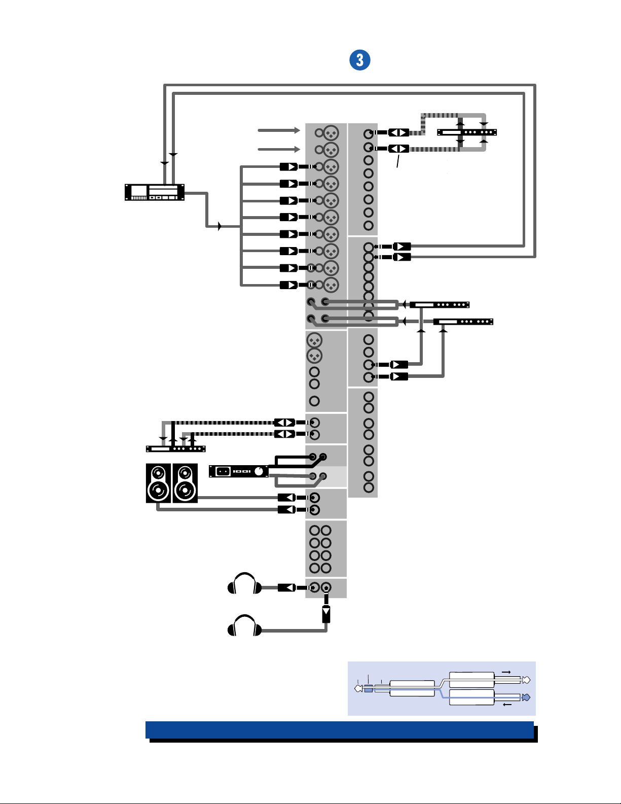
HOOKUP DIAGRAMS
In
8 Track Recorder
From Mics, Keys,
Drum machines
etc.
Out
123459-1011-12
CHANNEL INPUTS
BAL/UNBAL
MAIN OUT
LR L R
MONO
(See the diagram below which
shows how to wire Insert plugs)
CHANNEL INSERTS
1
2
BAL/UNBAL
DIRECT OUT
3
BAL/UNBAL
AUX SENDS
4
Stereo Compressor
EFX A
EFX B
Stereo Processor
Powered Monitors
Cassette Recorder
Headphones
MAIN
INSERT
AUX RETURNS
IN
TAPE
OUT
TAPE
C/R OUT
BAL/UNBAL
BAL/UNBAL
SUB OUTS
OUT
PHONES
This is an insert plug, used to send and receive
on the same TRS connector
ring
tip
This plug connects to one of the
mixer’s Channel Insert jacks.
sleeve
(TRS plug)
SEND to processor
RETURN from processor
“tip”
“ring”
1642-VLZ PRO 8-Track Tracking
6
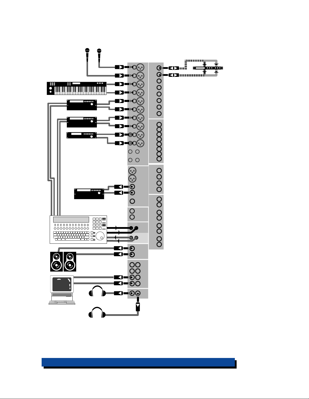
Keyboard
Video
Decks
Stereo Compressor
CHANNEL INSERTS
CHANNEL INPUTS
Multi-VCR
Video Switcher
Computer
with Audio Card
CD Player
Video
Master
Powered
Monitors
in
Headphones
LR L R
MONO
BAL/UNBAL
MAIN OUT
MAIN
INSERT
IN
TAPE
OUT
TAPE
C/R OUT
BAL/UNBAL
BAL/UNBAL
SUB OUTS
OUT
PHONES
BAL/UNBAL
DIRECT OUT
BAL/UNBAL
AUX SENDS
AUX RETURNS
1642-VLZ PRO Video setup
7
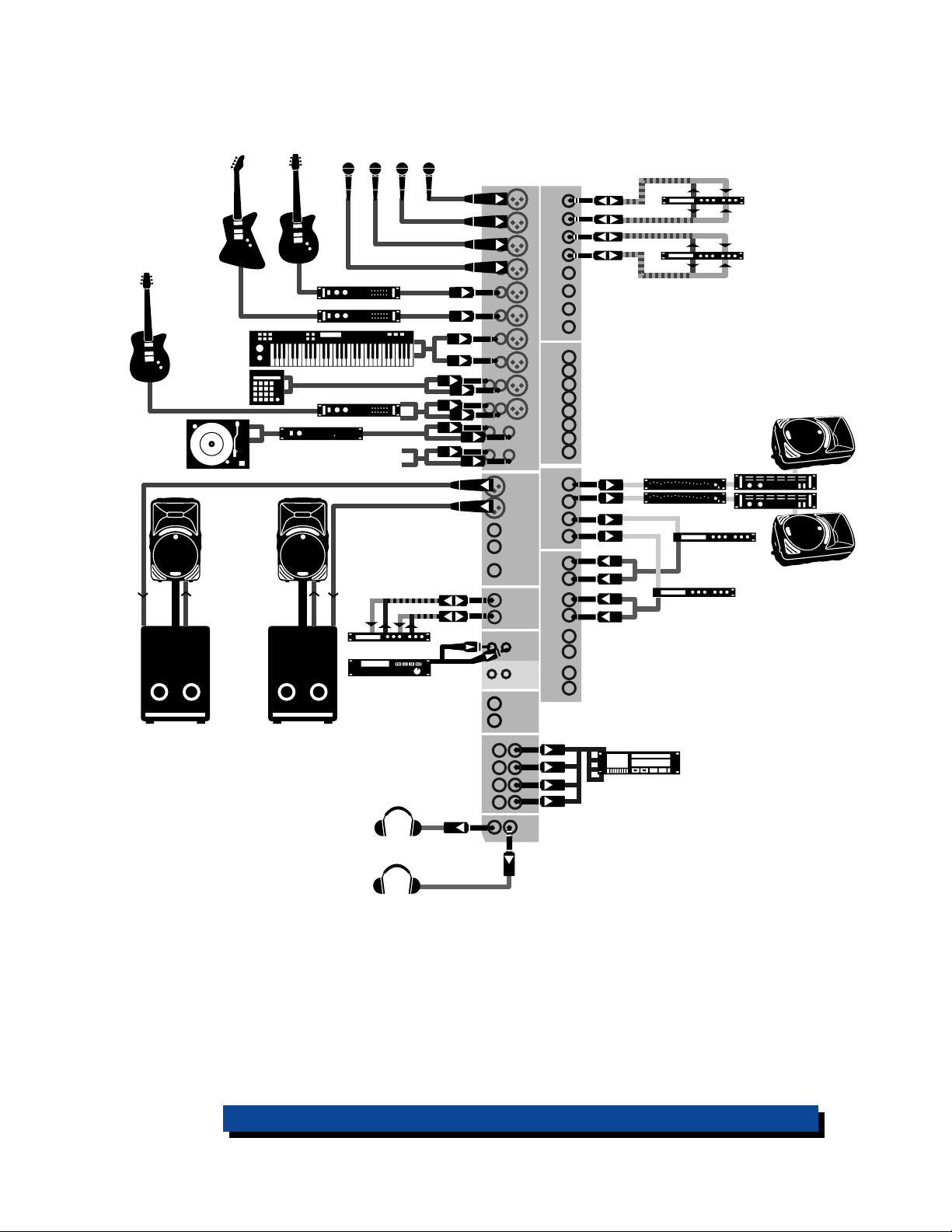
Mic 1-5
Guitar
Turntable
Bass
Keyboard
Drum
Machine
Active
PA Speaker/
Subwoofer
combination
(Pole-mounted
SRM450s and
SRS1500 active
Subwoofers
pictured)
Guitar
Mono Effects
Stereo Effects
Phono preamp
Additional
stereo source
Stereo Processor
CD Player
CHANNEL INPUTS
BAL/UNBAL
MAIN OUT
LR L R
MONO
MAIN
INSERT
IN
TAPE
OUT
TAPE
CHANNEL INSERTS
BAL/UNBAL
DIRECT OUT
BAL/UNBAL
AUX SENDS
AUX RETURNS
Stereo Compressors
Mono EQs, M-1400i Amps,
and (C300) Passive Stage Monitors
Processor
Processor
C/R OUT
BAL/UNBAL
SUB OUTS
OUT
PHONES
Digital Multitrack
Recorder
Headphones
1642-VLZ PRO Stereo P.A.
8
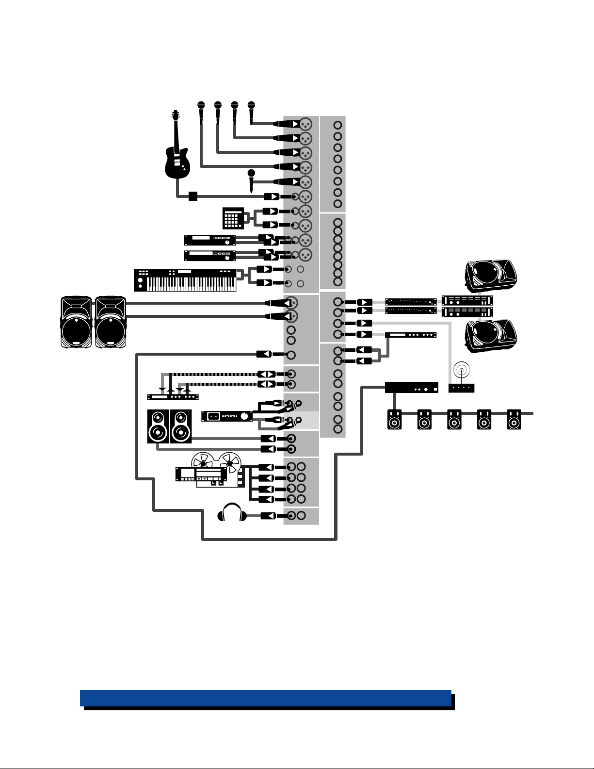
Mic 1-5
SRM 450s or other
powered monitors
HR824s or other
powered monitors
Guitar
Direct Box
Drum Machine
CD Player
VCR
Keyboard
Stereo Processor
Cassette Recorder
CHANNEL INPUTS
BAL/UNBAL
MAIN OUT
LR L R
MONO
MAIN
INSERT
IN
TAPE
OUT
TAPE
C/R OUT
BAL/UNBAL
CHANNEL INSERTS
BAL/UNBAL
DIRECT OUT
BAL/UNBAL
AUX SENDS
AUX RETURNS
Mono EQs, M-1400i Amps,
and (C300) Passive Stage Monitors
Processor
70 Volt Line Amp
Assistive Listening
Transmitter
Monitors on distributed system throughout building
BAL/UNBAL
Multitrack Recorder
Headphones
SUB OUTS
OUT
PHONES
1642-VLZ PRO Chur ch Installation
9
P A TCHBAY DESCRIPTION
At the risk of stating the obvious, this is
where you plug everything in: microphones,
line-level instruments and effects, and the ultimate destination for your sound: a tape
recorder, PA system, etc. Many of the features
described in this section are on top of the
mixer, but some are on the rear panel.
E-Z INTERFACING
Concerned about levels,
balancing, impedances, polarity, or other interface
goblins? Don’t be. On your
1642-VLZ
PRO, you can patch anything almost
anywhere, with nary a care. Here’s why:
• Every input and output is balanced
(except inserts, phones and RCA jacks).
• Every input and output will also accept
unbalanced lines (except XLR jacks).
• Every input is designed to accept virtually
any output impedance.
• The main left and right mix outputs can
deliver 28dBu into as low as a 600 ohm load.
• All the other outputs can deliver 22dBu
into as low as a 600 ohm load.
• All the outputs are in phase with the inputs.
All we ask is that you perform the Level-Setting
Procedure
every time you patch in a new
sound source. So stop worrying and start mixing!
MIC AND LINE INPUT FLEXIBILITY
Channels 1-8 are mono channels with
and
LINE
inputs, featuring our new XDR Extended Dynamic Range mic preamp circuitry.
Channels 9-10 and 11-12 are stereo pairs with
LINE
left and right
inputs and a single
put feeding each pair . Channels 13-14 and
LINE
15-16 are stereo pairs with
inputs only.
MIC
MIC
in-
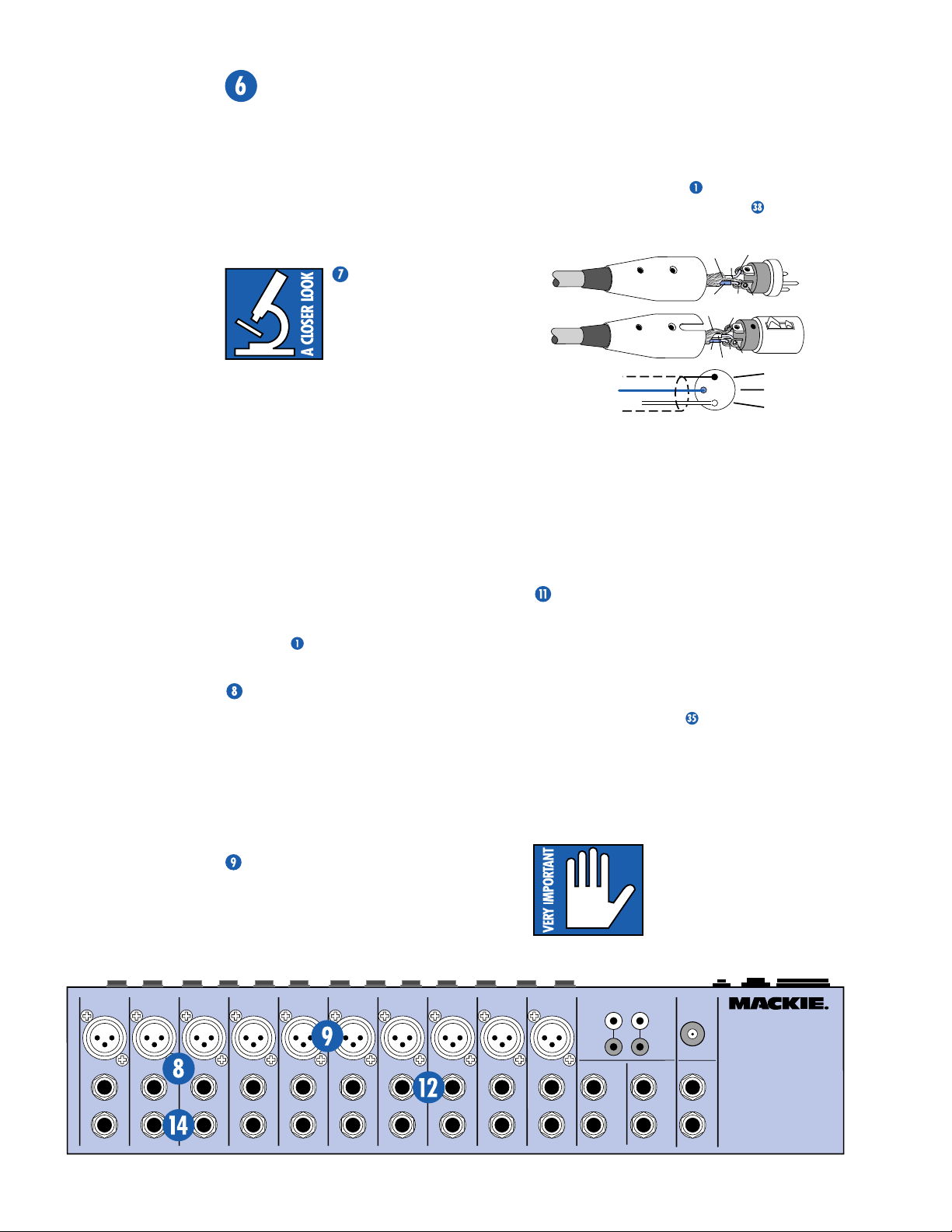
MIC INPUTS
We use phantom-powered, balanced microphone inputs just like the big studio megaconsoles, for exactly the same reason: This
kind of circuit is excellent at rejecting hum
and noise. You can plug in almost any kind of
mic that has a standard XLR-type male mic
connector. Always be sure to perform the
Level-Setting Procedure
nals are routed from these inputs:
. To learn how sig-
. If you
wire your own, connect them like this:
COLD
3
HOT
2
HOT
1
3
1
3
2
1
2
SHIELD
COLD
HOT
SHIELD
SHIELD
COLD
Pin 1 = ground or shield
Pin 2 = positive (+ or hot)
Pin 3 = negative (– or cold)
Professional ribbon, dynamic, and condenser mics will all sound excellent through
these inputs. The 1642-VLZ
PRO’s mic inputs
will handle almost any kind of mic level you
can toss at them, without overloading.
A WORD ABOUT PHANTOM POWER
Most condenser mics require phantom power,
where the mixer sends low-current DC voltage to
the mic’s electronics through the same wires
that carry audio. The 1642-VLZ
power is globally controlled by the
switch on the rear panel .
Semipro condenser mics often have batteries to accomplish the same thing. “Phantom”
owes its name to an ability to be “unseen” by
®
dynamic mics (Shure
SM57/SM58, for instance) that don’t need external power and
aren’t affected by it anyway.
Unless you know for
certain it is safe to do so,
never plug single-ended
(unbalanced) microphones, instruments or
electronic devices into the
the phantom power is on.
PRO’s phantom
PHANTOM
MIC
input jacks if
MIC
R
D
X
LINE IN
INSERT
TAPEINTAPE
MIC
1
M
I
C
P
D
R
X
E
LINE IN
BAL
UN
-
BAL
INSERT
MIC
2
M
I
C
R
P
D
R
X
E
LINE IN
BAL
UN
-
BAL
INSERT
MIC
3
M
I
C
R
P
D
R
X
E
LINE IN
BAL
UN
-
BAL
INSERT
MIC
4
M
I
C
R
P
D
R
X
E
LINE IN
BAL
UN
-
BAL
INSERT
MIC
5
M
I
C
R
P
D
R
X
E
LINE IN
BAL
UN
-
BAL
INSERT
MIC
6
M
I
C
R
P
D
R
X
E
LINE IN
BAL
UN
-
BAL
INSERT
MIC
R
D
X
LINE IN
INSERT
MIC
8
M
I
C
P
R
E
BAL
UN
-
L
BAL
LINE IN 10
R
7
M
I
C
R
P
R
E
BAL
UN
-
BAL
9-10
M
R
D
X
LINE IN 9
MIC
11-12
M
I
C
I
C
R
P
R
P
D
R
X
E
E
LINE IN 11 LINE IN LINE IN
BAL
UN
BAL
BAL
UN
-
L
R
LINE IN 12
-
BAL
RIGHT
LEFT
MONOMONOMONO
13
LEFT
BAL/
UNBAL
14
RIGHT
OUT
LEFT
RIGHT
MONO
LEFT
BAL/
UNBAL
RIGHT
LAMP
PHONES
15
16
12V
0.5A
A
B
WITH PREMIUM XDR
1642-VL ZPRO
16-CH ANNEL MIC/ LINE MIX ER
TM
MIC PREAMPLIFIERS
10
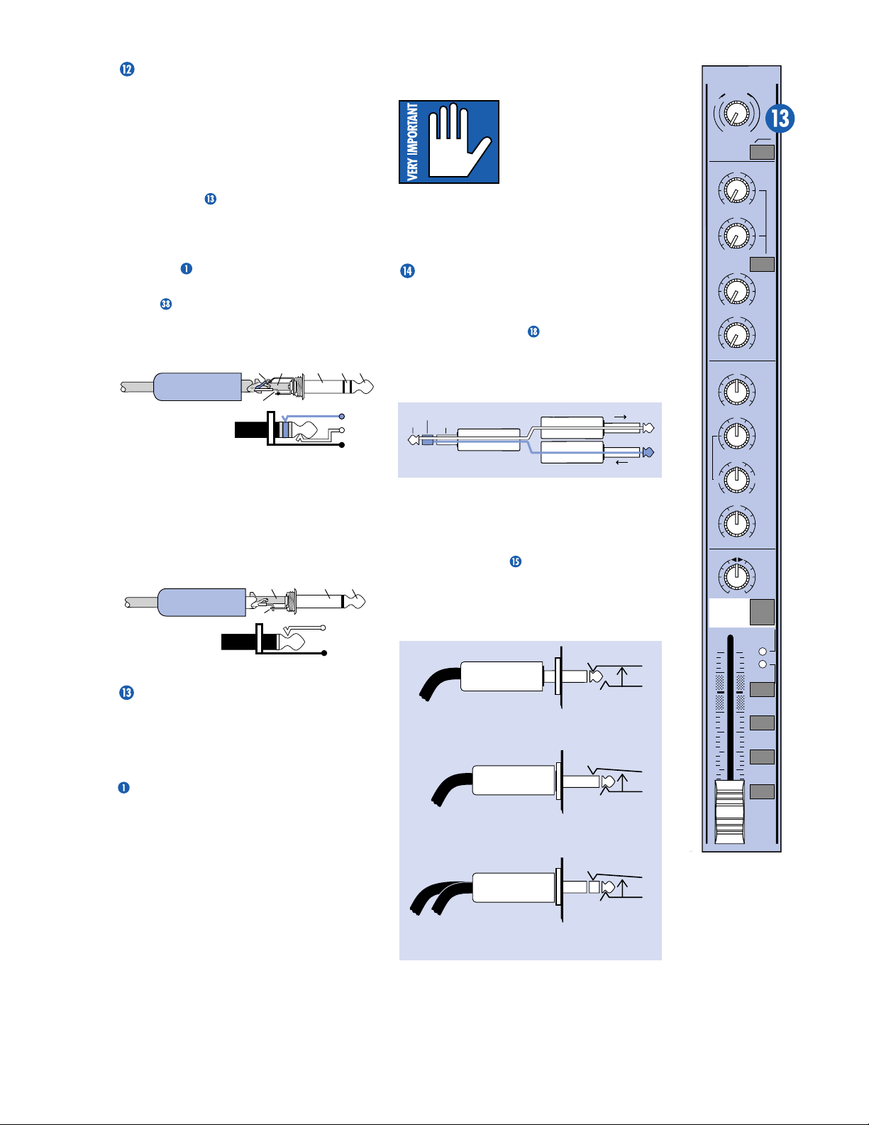
LINE INPUTS
These 1/4" jacks share circuitry (but not
phantom power) with the mic preamps. You
can use these inputs for virtually any signal
you’ll come across, from instrument levels as
low as –50df to operating levels of –10dBV to
+4dBu, as there is 45dB of gain available via
TRIM
the
knob .
Note that channels 1-8 line inputs are
intially attenuated by 15dB.
Always be sure to perform the
Procedure
.
Level-Setting
To learn how signals are routed from these
inputs:
inputs, use a
. To connect balanced lines to these
1
/4" tip-ring-sleeve (TRS) plug,
the type found on some stereo headphones:
TIPSLEEVE
SLEEVERING
TIP
Tip = positive (+ or hot)
RING
RING (COLD)
TIP (HOT)
SLEEVE
(SHIELD)
Ring = negative (– or cold)
Sleeve = shield or ground
To connect unbalanced lines to these in-
1
puts, use a
/4" mono (TS) phone plug or
standard instrument cable:
SLEEVE
TIP
Tip = signal (+)
Sleeve = ground
TIPSLEEVE
TIP (HOT)
SLEEVE
(SHIELD)
TRIM
These controls are the top row of knobs in
the channel strip section. Every time you plug
MIC
or
LINE
something into a
should perform the
Level-Setting Procedure
, and that procedure is basically “how to use
TRIM
the
MIC
knob.”
TRIM
adjusts the input sensitivity of the
and
LINE
inputs. This allows signals from
the outside world to be adjusted to optimal
internal operating levels.
Through the XLR jack (
0dB of gain with the knob fully down, ramping
to 60dB of gain fully up.
1
Through the
/4" input (
of attenuation fully down and 45dB of gain fully
U
up, with a “
” (unity gain) mark at 10:00.
This 15dB of attenuation can be very handy
when you are inserting a signal that is very hot,
or you want to add a lot of EQ gain, or both.
input jack, you
MIC
), there will be
LINE
), there is 15dB
Without this “virtual pad,” a scenario like that
might lead to channel clipping.
TRIM
The
controls for
stereo channels 9-10 and
11-12 are only used to adjust the Mic inputs. The
line inputs are set to unity
gain.
The
TRIM
controls for channels 13-14 and
15-16 only adjust the line level inputs, as they
have no Mic inputs.
INSERT
These 1/4" jacks are for connecting serial
effects processors such as compressors, equaliz-
. The
INSERT
ers, de-essers, or filters
TRIM
after the
EQ, LOW CUT,
control, but before the channel’s
fader and
MUTE
cables must be wired thusly:
ring
tip
This plug connects to one of the
mixer’s Channel Insert jacks.
sleeve
(TRS plug)
SEND to processor
RETURN from processor
Tip = send (to effects device input)
Ring = return (from effects device output)
Sleeve = common ground
Even though channels 1–8 already have
DIRECT OUT
jacks ,
INSERT
be used as channel direct outputs; post-
LOW CUT
preways you can use the
(TIP = SEND to effect, RING = RETURN from effect.)
, and pre-EQ. Here are three
INSERT
jacks:
MONO PLUG
Direct out with no signal interruption.
Insert only to first “click.”
MONO PLUG
Direct out with signal interruption.
Insert all the way in to the second “click.”
STEREO
PLUG
For use as an effects loop.
point is
controls. Insert
“tip”
“ring”
jacks can also
TRIM
Channel Insert jack
Channel Insert jack
Channel Insert jack
TRIM
B
d
0
V
1
-
G
A
C
I
N
I
1
M
U
060
+15dB -45dB
LOW CUT
75 Hz
18dB/OCT
AUX
U
1
OO
+15
U
2
OO
+15
PRE
U
3
OO
+15
U
4
OO
+15
EQ
U
HI
12k
+15-15
U
MID
15
+15
-
800
FREQ
2k200
8k100
U
LOW
80Hz
+15-15
PAN
,
LR
1
MUTE
dB
10
5
U
5
10
20
30
40
50
60
OO
OL
-
SOLO
1
3
L/R
REC
20
-
2
-
4
1
11

DIRECT OUT (on rear panel)
Found only on channels 1–8, these 1/4" jacks
deliver the signal from the very end of the
TRIM
channel path; post-
CUT
, post-fader and post-
, post-EQ, post-
MUTE
. You can use
these for recording, making the 1642-VLZ
LOW
PRO
perfect for an 8-track studio.
RECORDING
When recording, you use the first two channels for your sound sources: vocal mics, drum
mics, keyboard/synth outputs, guitar effects
outputs, that sort of thing. From there, the
channels manipulate the sound, but are not assigned to the output section. Instead, they’re
patched from the channel’s
DIRECT OUT
to any of your 8 multitrack inputs. This allows
recording of two tracks at a time. By reconnecting the Direct Outs to the different tape
inputs, you can record to all of the 8 tracks.
Once the tracking is completed, the outputs
of the multitrack are then patched to channels
LINE
3-12
track out 1 to
Aha! That’s why it says “
nel 3’s fader, “
inputs on the 1642-VLZ PRO (multi-
LINE
input 3, 2 to 4, 3 to 5, etc.).
TRACK 2
TRACK 1
” next to channel 4, and
” next to chan-
so forth. These channels (3–12) will be assigned to the mixer’s output section, delivering
the signals to their ultimate destination, which
may be your mixdown 2-track, your control
room system, or your headphones.
But let’s not forget that the 1642-VLZ
a 4-bus mixer. These buses lead to the
, and are designed to accomplish the
OUTS
task of getting channels to the multitrack without using the direct outputs.
For example, a channel is assigned to
SUB OUT 1. SUB OUT 1
’s output is patched to
multitrack input 1. From there, the multitrack
output goes to the mixer’s channel 3
as we just discussed. (Hot tip: To feed an 8track deck with 4 sub outputs, the 1642-VLZ
PRO has double busing, which simply means
that bus 1 feeds
bus 2 feeds
feeds
feeds
SUB OUT
SUB OUT 2
SUB OUT 3
SUB OUT 4
s to the inputs of the 8-track deck.
SUB OUT 1
and
and
and
SUB OUT 5
and
SUB OUT 6
SUB OUT 7
SUB OUT 8
Tracks in record mode will accept the signal,
and tracks in safe mode will ignore the signal.)
jacks
PRO is
SUB
LINE
input,
, bus 3
, and bus 4
. Patch the 8
,
The advantages: You can assign any channel
to any track, without repatching. You can assign multiple channels to one track and control
the overall level of that subgroup
. You can’t
bounce tracks without this feature.
By returning the outputs of the effects processors to 13/14 (EFX A) and 15/16 (EFX B),
you can choose to record or Monitor with effects.
Perhaps the best recording method is a
combination of both approaches: Use the
to feed multichannel submixes (like a
OUTS
SUB
drum kit) to some of the tracks, and the
DIRECT OUT
jacks to feed single-channel sig-
nals (like bass guitar) to the other tracks.
The point is that you never listen directly to
the source channels. You listen to the monitor
channels (3–12) and they’re listening to the multitrack that is listening to the source channels.
The main advantage is that you won’t be forced to
constantly repatch your multitrack — just set it
up and forget it. Y ou’ll also know for certain that
the signals are indeed getting to the multitrack,
since you’re constantly listening to it.
Another method of interfacing a multitrack is
called inline monitoring, and requires a mixing
console dedicated to that, like the Mackie
8•Bus. Each of its channels is actually two channels: one carrying the mic/line sound source and
the other carrying the multitrack output.
AUX SEND OUTPUTS
These 1/4" jacks usually patch to the inputs
of your parallel effects devices
puts of your stage monitor amps. To learn how
signals are routed to these outputs, see the Aux
discussion on page 25.
or to the in-
12