

Mace HydroMace 3000 Product Manual
PRODUCT MANUAL
www.macemeters.com
MACE HydroMace 3000 Product Manual
Product Support
Should you experience diculty in using this product, please contact your
supplier.
We also welcome feedback from customers who feel that their experience may
provide an improvement to the product or may be benecial to other users.
Please go to www.macemeters.com
Disclaimer
No warranties of any nature are extended by this document.
Measuring and Control Equipment Co. Pty. Ltd. (MACE) will not accept any
nancial or other responsibility that may be the result of your use of this
information, including direct, indirect, special or consequential damages.
You must be careful to ensure that the use of this information complies with
the laws, rules and regulations of the jurisdictions with respect to which it is
used.
MACE assumes no responsibility for personal or property damage caused by
the misuse of this equipment.
Copyright
Information in this document is subject to change without notice. The
software described in this document is furnished under a license agreement
or nondisclosure agreement. The software may be used or copied only in
accordance with the terms of those agreements. No part of this publication
may be reproduced, stored in a retrieval system, or transmitted in any form or
any means electronic or mechanical, including photocopying and recording
for any purpose other than the purchaser’s personal use without the written
permission of Measuring & Control Equipment P/L.
Copyright © 1996-2009. MACE P/L. All rights reserved.
Part No. 825-319 Rev. 1.4 Code. 080209
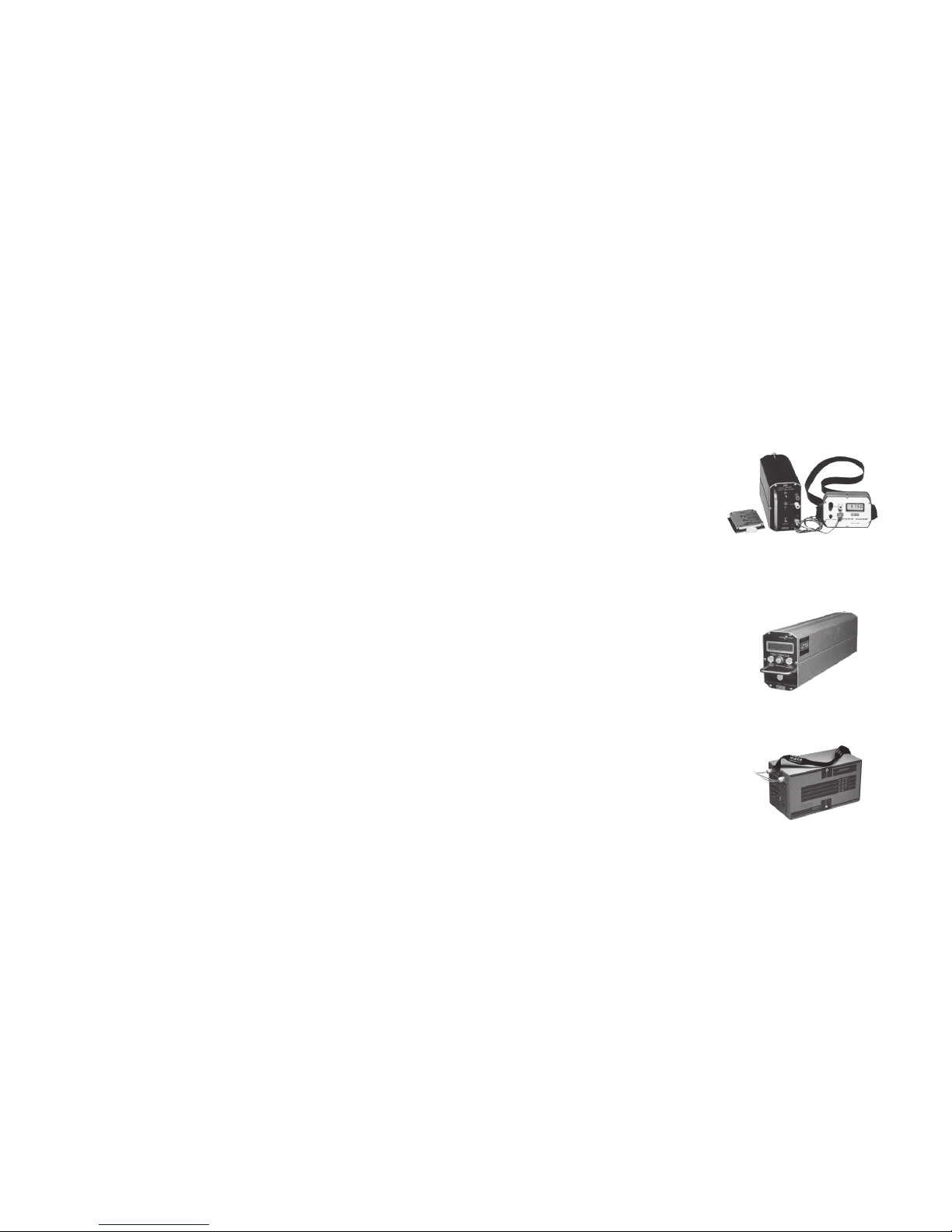
40 years of innovation from the inventors
of solid state data logging
DFR-77 DATA LOGGER
1977 - The world’s first commercial EPROM
data loggers, the MACE DFR-77 were delivered.
Hundreds of these instruments were used
throughout Australia and Papua New Guinea
working under the harshest imaginable
conditions. The EPROM data recording technique
proved to be the most reliable method of
electronic data storage.
HYDROMACE TRS
1984 - MACE introduced the Hydromace system
which gave environmental field stations the combined
capabilities of data logging, control, telemetry via
telephone, radio or satellite and intelligent response to
both computer or human interrogation.
HYDROMACE 2000
1992 - The HydroMace 2000 data logger provided
multi-channel logging and control in water
catchments, sewer treatment plants and industrial
pollution applications. A leader in its time, many
are still in use in catchment management and flood
warning networks across Australia.

1.0 Introduction to HydroMace 3000 1
2.0 Warnings 2
3.0 Installing HM 3000 power options 3
3.1 Solar panel installation on a 2” pole 3
3.2 Installing a MACE mains powered trickle charger 6
3.3 Powering the HM 3000 with an external battery 7
4.0 Electronics module 8
5.0 Installing the HM3000 on a 2” pole 10
5.1 Sensor and power cables routed inside the pole 10
5.2 Sensor and power cables routed through conduit 12
6.0 Installing the HM3000 on a wall 13
7.0 The I/O (Input/Output) card 14
8.0 Wiring digital inputs 15
9.0 Wiring analogue inputs 16
10.0 Wiring digital outputs 18
11.0 Wiring analogue outputs 18
12.0 Installing additional cards 19
13.0 Installing a Series3 FloSI card 20
14.0 Maintenance 21
14.1 Battery maintenance 21
14.2 Solar panel maintenance 21
14.3 Sensor maintenance 22
14.4 Depth sensor reference lter maintenance 22
Section A: Hardware Manual
CHAPTER PAGE
This is an interactive PDF
This user manual is setup as an interactive PDF. The user can click on
any of the “Chapters” in the Table of contents to navigate directly to the
corresponding page. To return to the Table of contents click on the “Return to
TOC” button at the bottom of each page.
References to chapters in the body text are hyperlinks.

Section B: Software Manual
CHAPTER PAGE
21.2 The order and removal of channels 50
21.3 Editing a channel 51
21.3.1 Edit “Depth” channel type 52
21.3.2 Edit “4-20mA” input type - I/O card 55
21.3.3 Edit “Frequency”, “Voltage” and “Shaft encoder” input type - I/O card 56
21.3.4 Edit “Flowrate (Velocity)” channel type 57
21.3.5 Edit a “Flowrate (Weir)” channel type 62
21.3.6 Edit a “Total” channel type 66
21.3.7 Edit a “Event - pulse” channel type 67
21.3.8 Edit a “Event - status change” channel type 68
21.3.9 Edit a “Input total pulse” channel type 69
21.3.10 Edit a “Binary” channel type 70
22.0 Congure outputs 71
22.1 Adding outputs 71
22.2 Editing outputs 73
23.0 Conguring FloSI Card 75
23.1 Conguring a FloSI 75
23.2 Serial Interface Settings 76
23.3 Ordering the SDI-12 or ASCII Output String 80
24.0 Real time data 81
25.0 Start/Stop device 82
26.0 Disconnect 82
27.0 View totals 83
28.0 Downloading stored data 84
29.0 View downloaded data le 84
Appendix A - Flume/weir coecients 88
Section B: Software Manual
CHAPTER PAGE
15.0 Introduction to FloCom+ 25
16.0 Installing the software 26
17.0 Connecting to the device 28
17.1 Connecting to the device using the serial port 28
17.2 What to do if the password is lost/forgotten 29
18.0 System information 30
19.0 HM3000 settings dialogue box 32
19.1 General settings 33
19.2 Sensor power 34
19.3 View conguration 34
19.4 Reset conguration 34
20.0 Congure modules 35
20.1 Adding a module 35
20.2 Removing a congured module 35
21.0 Congure channels 36
21.1 Adding a new channel 36
21.1.1 Add a “Velocity” channel type - I/O card (4-20mA) 37
21.1.2 Add a “Velocity” channel type - I/O card (Frequency) 38
21.1.3 Add a “Depth” channel type - I/O card (4-20mA) 39
21.1.4 Add a “Depth” channel type - I/O card (Shaft encoder) 40
21.1.5 Add a “Flowrate (Velocity)” channel type - I/O card 41
21.1.6 Add a “Flowrate (Weir)” channel type 42
21.1.7 Add a “Total ow” channel type 44
21.1.8 Add a “Event - pulse” channel type 45
21.1.9 Add a “Event-status change” channel type 46
21.1.10 Add a “Input pulse total” channel type 47
21.1.11 Add a “Binary” channel type - I/O card 48
21.1.12 Add a “User dened” channel type - I/O card (Voltage) 49
RetuRn to toC
MaCe HydR oMaCe 3000 PROD UCT MANUA L 1
Section A:
Hardware Manual
Mace HydroMace 3000
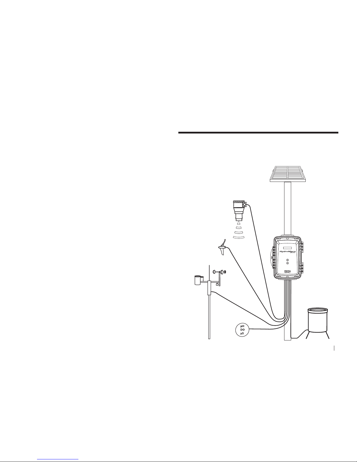
1.0 Introduction to HydroMace 3000
This manual describes the installation, use and maintenance of the HydroMace
3000. The HydroMace 3000 typically consists of four main components:
• Theelectronicsmodule.
• Thesensor(s).
• Thesolarpanel(orpowersupply).
• Flocom+ software enabling you to congure
and download your HydroMace 3000.
Rainfall
Gauge
Ultrasonic
Depth
Sensor
Electronics
Module
Solar Panel
Weather
Station
Multiple
Water
Quality
Sensors
Multiple
Flow Sensors
2 SeCtion a HARDWARE MANUAL
RetuRn to toC
RetuRn to toC
MaCe HydR oMaCe 3000 PROD UCT MANUA L 3
2.0 Warnings
2.1 Intrinsic Safety
The HydroMace 3000 is NOT an intrinsically safe instrument and should not be
installed in hazardous (explosive) environments. Should an intrinsically safe
instrument be required, MACE can oer other instruments with this approval
level.
2.2 Floods
MACE recommends that the HydroMace 3000 electronics module be
mounted above known ood peak levels. MACE will not be liable for damage
caused by ooding. (The unit is weatherproof, but NOT waterproof and
should NOT be submerged).
2.3 Sunlight
MACE recommends that the HydroMace 3000 electronics module be
mounted so that the LCD faces in a direction away from direct sunlight (ie
South in the Southern Hemisphere and North in the Northern Hemisphere).
2.4 Cable damage
MACE recommends that all cables be appropriately routed through electrical
conduit or other similar mechanism. MACE will not be liable for damage to
cables, especially if it is caused by vehicles, digging implements, animals or
debris in the pipe or channel.
2.5 Insects and moisture
After the HydroMace 3000 system has been installed and fully tested, MACE
recommends the use of expanding “space ller” foam down the rst 5 to 10cm
(2 to 4 “) of the conduit or mounting pole to prevent insect/moisture ingress.
2.6 Battery life
Care must be taken when a mains power supply is used to charge the internal
battery instead of a solar panel. If the mains power remains disconnected
for an extended period of time, the internal battery may be permanently
damaged.
2.7 Electromagnetic compatibility (EMC)
This is a Class A product. In a domestic environment this product may cause
radio interference in which case the user may be required to take adequate
measures.
3.0 Installing HM 3000 power options
3.1 Solar panel installation on a 2” pole
The solar panel is used to charge the internal battery of the HydroMace 3000
where mains power is unavailable.
Users are advised to ascertain the suitability of solar panels for
their application by checking relevant solar radiation maps for
their region (for example those found at http://rredc.nrel.gov/
solar/old_data/nsrdb/redbook/atlas/ ). As a guideline, for an
HM 3000 with three I/O cards and measuring every ve minutes,
at least three hours sunlight is required per day
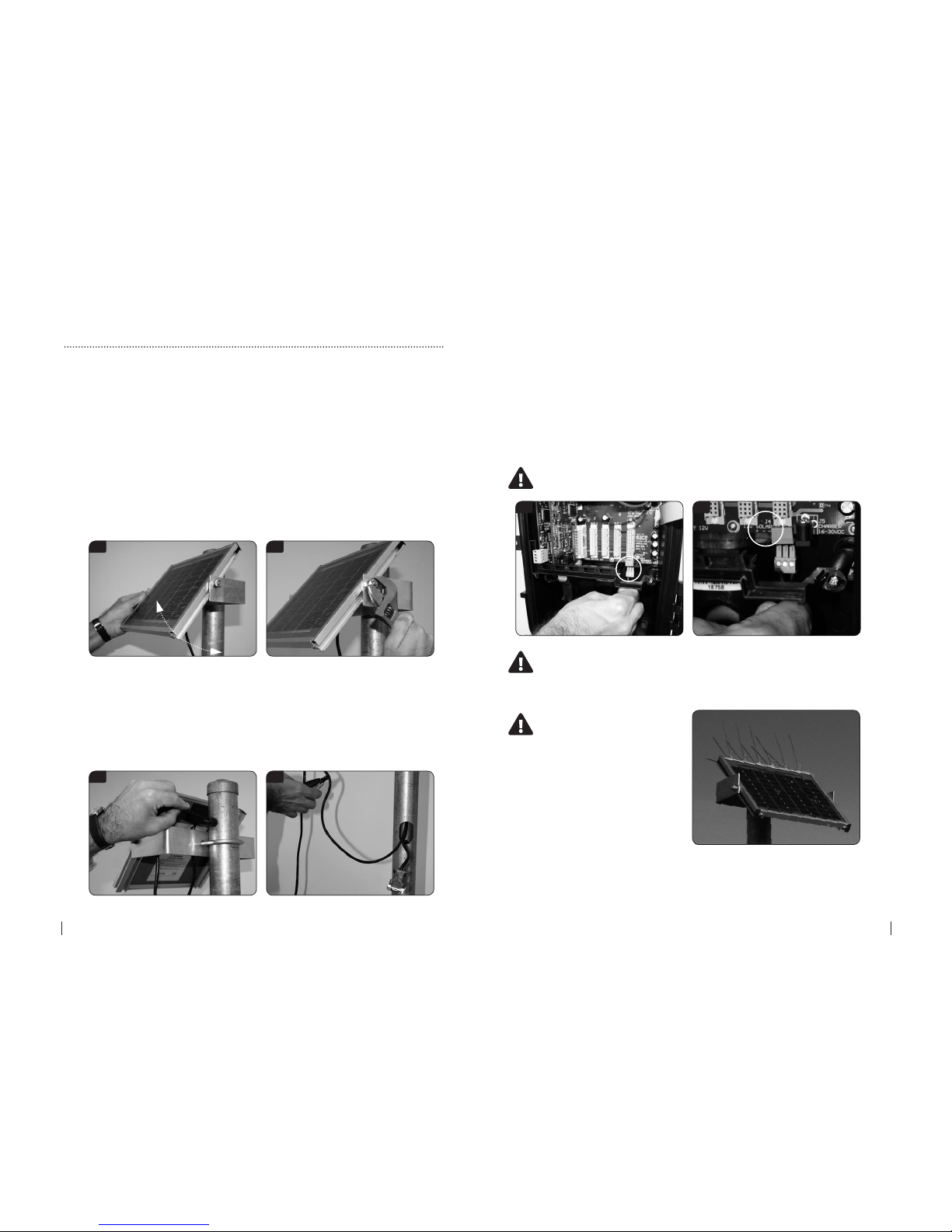
1. Place an M8 bolt with M8 at washer through the hole in left arm of the
mounting bracket. Ensure that the head of the bolt is on the INSIDE and the
thread faces outward.
2. On the OUTSIDE of the bracket, place an M8 spring washer then an M8 nut.
DO NOT TIGHTEN THE NUT.
3. Repeat these two steps on the right hand side of the bracket.
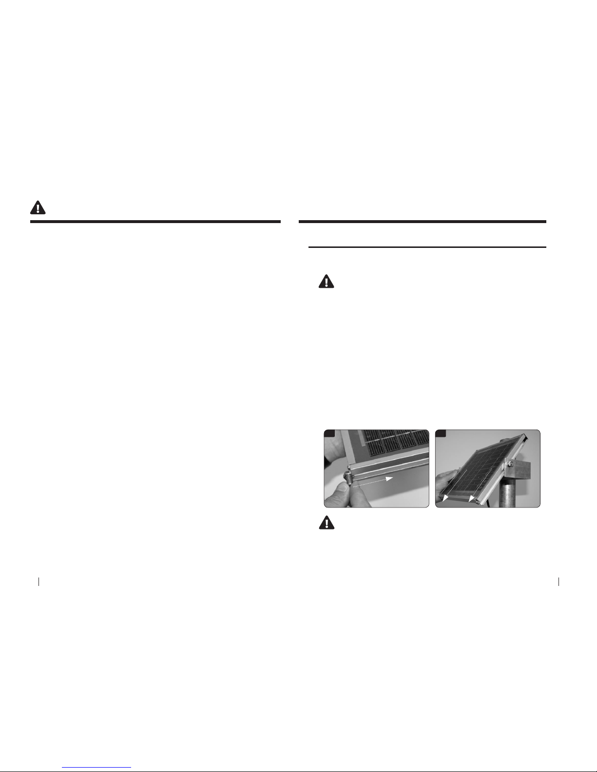
4. Holding the solar panel carefully, hold it above the two arms of the
mounting bracket.
5. Slide the solar panel down so that the head of each of the M8 bolts ts in
the channel on either side of the solar panel.
Ensure that the gutter of the solar panel is positioned between
the at washer and the head of the M8 Bolt
7. Place the u-bolt provided in the solar panel mounting kit around the pole.
5 5
4 SeCtion a HARDWARE MANUAL
RetuRn to toC
RetuRn to toC
MaCe HydR oMaCe 3000 PROD UCT MANUA L 5
8. Place the solar panel mounting bracket onto the u-bolt. Ensure that the
arms of the bracket face out from the pole and that the mounting hole on
each arm is towards the top of each arm.
9. Slide the bracket to the desired position on the pole, taking care to place it
at the desired height and so that the open face of the bracket faces towards
the sun.
10. Place the 3/8” at and spring washers on to the U-bolt and tighten the two
nuts so that the bracket is secured on the pole.
11. Tilt the solar panel so that the active side faces towards the sun (North in
Southern hemisphere, South in Northern hemisphere) at an angle specied
in the data sheet provided. (your latitude + 15°).
11 12
12. Now tighten the M8 nuts on each side of the mounting bracket to secure.
13. The cables from the solar panel/charger to the electronics unit must be
enclosed to minimise exposure to the elements. The cable should be either
routed through conduit or through the solar panel mounting pole. You will
need a hole drilled in the mounting pole at the top near the solar panel as
well as a cut away where the electronics unit is to be mounted. Refer to the
pictures below.
13 13
3.1 Solar panel installation on a 2” pole - Continued
14. Ensure that the cable from the solar panel is terminated using the threepin connector provided in the electronics box and that the polarity is correct.
The photo below shows the location of the three-pin connector inside the
HM 3000.
15. The polarity is labelled on the circuit board near the connector in the
photo below.
NOTE: When wiring the solar panel either of the ground (-ve)
terminals may be used
14 15
NOTE: The electronics module should be installed before
connecting the solar panel. Refer to the next chapter on the
electronics module for more detail
MACE highly reccomends
the use of Tri-spikes on the
top of the solar panel to
reduce accumulation of bird
droppings on the front face
of the solar panel
6 SeCtion a HARDWARE MANUAL
RetuRn to toC
RetuRn to toC
MaCe HydR oMaCe 3000 PROD UCT MANUA L 7
1
1
1
1
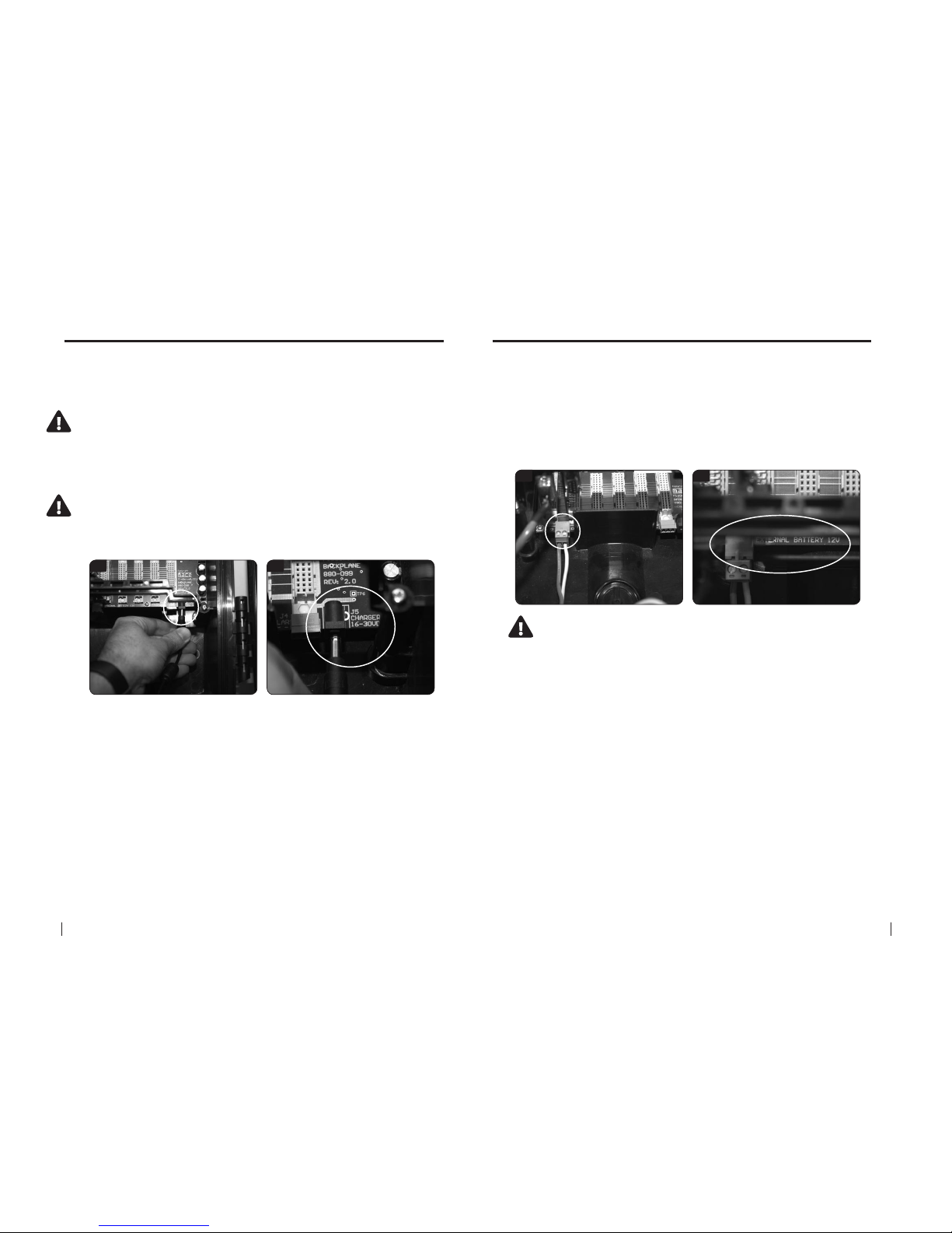
3.2 Installing a MACE mains powered trickle charger
In certain applications or where the use of a solar panel is impractical or
undesirable, the HM 3000 can be powered from any DC source of 16-30 Volts
(2Amps).
When the ambient temperature is less than -10°C (14F), the battery
should be removed to avoid permanent damage to the battery. The
HM 3000 should be powered by an external power source
1. The charger available from MACE (Part No. 850-323) comes complete with
a circular barrel connector that plugs directly into the electronics module.
The barrel connector for the 16-30VDC charger input is centre positive
2. Alternatively, if a DC source other than a MACE charger is used, this
is terminated using the same three-pin connector as for the solar panel
described above.
3.3 Powering the HM 3000 with an external battery
In certain applications, it may be desirable to power the HM 3000 with an
external battery.
1. The HM 3000 can be powered by an external 12V battery through the
dedicated “External Battery 12V” terminal. See photos below.
2. If a solar panel is connected to the HM 3000 as in Chapter 3.1, the internal
charging circuit of the HM 3000 will also charge the external battery. The
charging circuitry of the HM 3000 has a 20 Watt capacity.
If the external battery is charged via its own solar panel and NOT
through the HM 3000 charging circuit, the internal HM 3000
battery will discharge completely
8 SeCtion a HARDWARE MANUAL
RetuRn to toC
RetuRn to toC
MaCe HydR oMaCe 3000 PROD UCT MANUA L 9
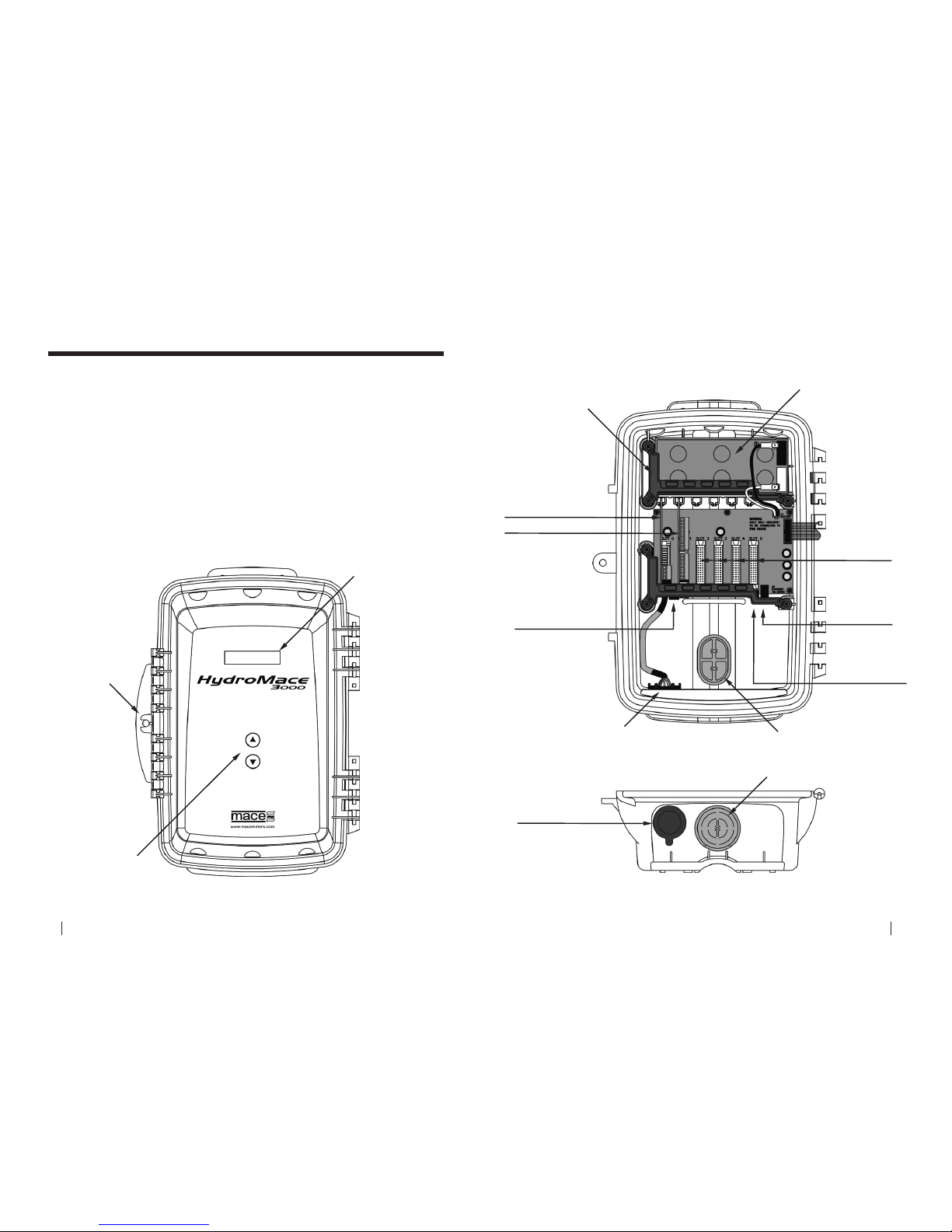
4.0 Electronics module
The electronics module is the central processing unit of the HydroMace 3000.
It includes the enclosure, battery and circuit boards that control the device.
On the front of the HydroMace 3000, a backlit liquid crystal display (LCD)
allows the user an on-site readout of parameter values and status messages.
Pressing either membrane switch will turn on the LCD.
The membrane switches can be used to scroll the display between the
various parameters being measured.
A serial communications port is located on the bottom face of the main
enclosure. Using the MACE serial data cable (Part No. 891-300) between this
port and a PC, users can congure, troubleshoot and download the device.
LCD Display
Secure Latch
with Padlock
Hole
Membrane Switches
(scrolls the display up & down)
ELECTRONICS MODULE - FRONT
NOTE: Door not shown
Conduit Cable Entry Point
Pole Cable Entry Point
12v Battery
Bracket
Charger Input
16-30VDC
(Centre of jack
is positive)
External Battery Input
12VDC
(Charged by Series3 Device)
Solar Panel/Charger
Input 16-30VDC
(Use with Solar Panel
or Mains Plug Pack)
Serial Communications Port
ELECTRONICS MODULE - INSIDE
ELECTRONICS MODULE - UNDERSIDE
Module Slots 2-5
Input/Output Module (slot 1)
Serial Communications Port
Controller Module (slot 0)
10 SeCtion a HARDWARE MANUAL
RetuRn to toC
RetuRn to toC
MaCe HydR oMaCe 3000 PROD UCT MANUA L 11
5.0 Installing the HM3000 on a 2” pole
The sensor and power cables can be routed either directly through the inside
of the 2” mounting pole or through electrical conduit. Installation directions
for both are provided below.
MACE recommends that the HM3000 electronics module be mounted so
that the LCD faces in a direction away from direct sunlight.
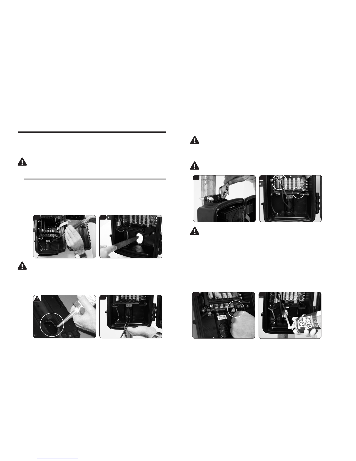
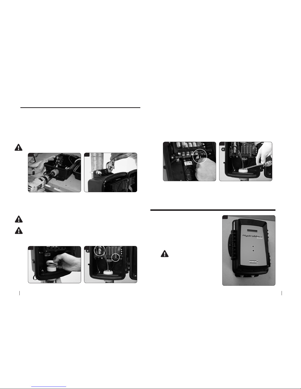
5.1 Sensor and power cables routed inside the pole
1. Place the electronics module on a work bench and using a hammer and
screwdriver carefully knock out the plastic cable entry point from the rear
of the enclosure. It is only thin plastic and is designed to break away at the
edges so work your way around the edge of the oval shape until the cover is
completely broken free of the unit.
2. File away any rough edges from the plastic cable entry point
1 2
3
4 5
6 7
3. Hold the electronics module up against the pole so that the oval cut-away
on the pole matches the cable entry point. Route the sensor and power
cables through the cable entry point as shown.
IMPORTANT: Apply NON-ACIDIC cure silicon sealant to the back of the
electronics module in the channel around the cable entry point. This will
stop water owing down the pole and into the electronics module
4. Use the two “U” bolts, 3/8” nuts and 3/8” washers provided to secure the
electronics module to the pole.
Do not overtighten the pole mounting bolts as permanent
damage may occur to the electronics enclosure
5. Plug in both the sensor cable and solar panel cable into the sockets as
shown in the picture below.
Sensor cables should be looped prior to connecting to act as a
form of strain relief.
Ensure that the cable from the solar panel/charger is terminated
using the three-pin connector provided in the electronics box and
that the polarity is correct. The polarity is labelled on the circuit
board near the connector
6. If using a 16-30VDC mains charger then plug this into the socket shown
in the picture below. Alternatively, the charger may be wired into the solar
panel screw terminal block (to the left of the socket).
7. Once all the cables are connected the system should be fully tested.
Assuming everything is connected and fully functional the cable entry point
should be lled with expanding “space ller” foam. This is to prevent insects
and/or moisture damaging the system.
12 SeCtion a HARDWARE MANUAL
RetuRn to toC
RetuRn to toC
MaCe HydR oMaCe 3000 PROD UCT MANUA L 13
5.2 Sensor and power cables routed through conduit
1. Place the electronics module on a work bench. Using a power drill and 2”
holesaw, carefully drill out the round plastic cable entry point at the base
of the unit as shown below. It is only thin plastic and is designed to break
away. Alternatively, the round cable entry point may be removed using the
“hammer and screwdriver” method described in Chapter 5.1.
2. Use the two “U” bolts, 3/8” nuts and 3/8” washers provided to secure the
electronics module to the pole.
Do not overtighten the pole mounting bolts as permanent damage may
occur to the electronics enclosure
1
2
3
4
5 6
3. Carefully attach an electrical conduit adaptor (Clipsal 50mm or Carlon 1 1/2”)
to the electronics module.
4. Plug in both the sensor cable and solar panel cable into the sockets as
shown in the picture below.
Sensor cables should be looped prior to connecting to act as a form of
strain relief
Ensure that the cable from the solar panel/charger is terminated using
the three-pin connector provided in the electronics box and that the
polarity is correct. The polarity is labelled on the circuit board near the
connector
5. If using a 16-30VDC mains charger then plug this into the socket shown
in the picture below. Alternatively, the charger may be wired into the solar
panel screw terminal block (to the left of the socket).
6. Once all your cables are plugged in you need to fully test the system.
When you are happy that everything is connected and working properly you
need to ll the cable entry point with expanding “space ller” foam. Fill down
the rst 5 to 10cm (2” to 4”) of the conduit. This is to prevent insects and/or
moisture damaging the system.
6.0 Installing the HM3000 on a wall
2
1. Follow instructions on the previous
page to drill out the cable entry point
for routing cables through conduit.
2. Use four M8 screws, bolts or coach
screws to secure the box to the wall.
(Use at washers between the screw
head and the box).
Do not overtighten the wall
mounting bolts as permanent
damage may occur to the
electronics enclosure
3. Follow instructions 3-6 on the
previous page for routing the cables
through conduit.
14 SeCtion a HARDWARE MANUAL
RetuRn to toC
RetuRn to toC
MaCe HydR oMaCe 3000 PROD UCT MANUA L 15
INPUTSOUTPUTS
TERMINALS
I/O CARD DIAGRAM
48 PIN CONNECTOR
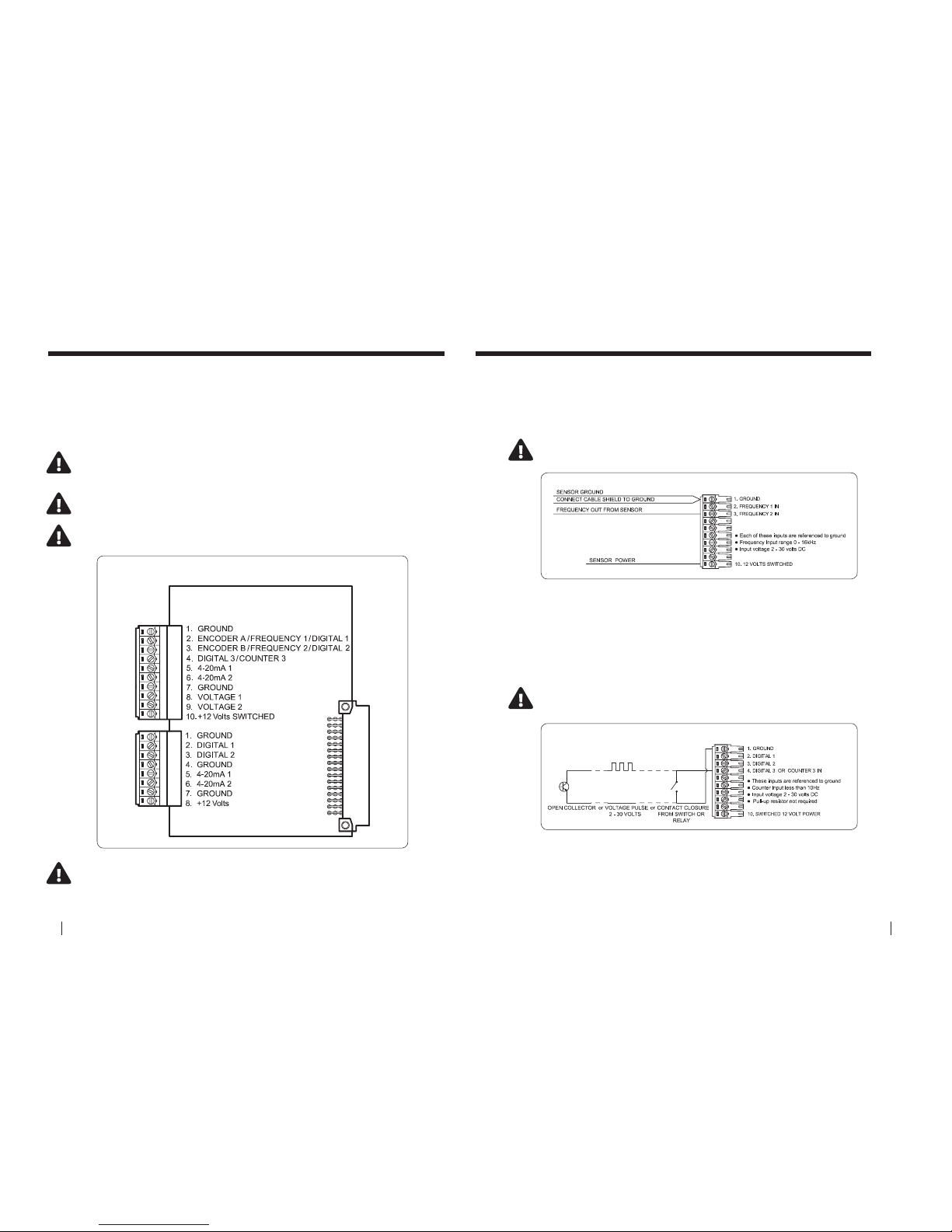
7.0 The I/O (Input/Output) card
The I/O card (module) supplied in the HydroMace 3000 provides the
inputs for connecting environmental monitoring sensors and outputs for
connection to ancillary devices.
The input and output terminals available on each I/O card are shown in the
diagram below.
MACE recommends the user studies the relevant documentation
supplied with each third party sensor prior to connection
Should insucient I/O be available on a single I/O card another card
(Part No. 850-329) should be purchased. HydroMace 3000 supports a
maximum of ve I/O cards
WARNING: The maximum system current available for powering sensors
attached to ALL I/O cards is 1.25 Amps at 12VDC
WARNING: The maximum input voltage on any terminal is 30VDC
FREQUENCY INPUT DIAGRAM
FREQUENCY INPUT DIAGRAM
DIGITAL OR COUNTER INPUT DIAGRAM
8.0 Wiring digital inputs
8.1 Frequency Input
Each I/O card provides up to two frequency inputs for connecting devices
such as ultrasonic depth sensors and/or ow meters. The frequency input
terminals available on each I/O card are shown in the diagram below.
8.2 Digital or Counter Input
Each I/O card provides up to three digital inputs or one counter input
for connecting devices such as rainfall gauges, hours run meters and/or
counting pulses. The digital/counter input terminals available on each I/O
card are shown in the diagram below.
NOTE: If a frequency input is wired a shaft encoder input is not
available
NOTE: If a shaft encoder input is wired only a single
digital/counter input is available
16 SeCtion a HARDWARE MANUAL
RetuRn to toC
RetuRn to toC
MaCe HydR oMaCe 3000 PROD UCT MANUA L 17
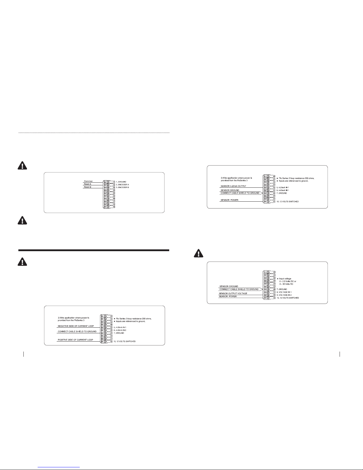
8.3 Shaft Encoder Input
Each I/O card provides one input for connecting a shaft encoder. The shaft
encoder input terminals available on each I/O card are shown in the diagram.
NOTE: If a shaft encoder input is wired only a single
digital/counter input is available. NO frequency input is available
Should the eld application require a shaft encoder and a frequency
input another I/O card (Part No. 850-329) should be purchased
8.0 Wiring digital inputs - Continued
FREQUENCY INPUT DIAGRAM
DIGITAL OR COUNTER INPUT DIAGRAM
SHAFT ENCODER INPUT DIAGRAM
2 - WIRE 4-20mA INPUT DIAGRAM
2 - WIRE 4-20mA INPUT DIAGRAM
3 - WIRE 4-20mA INPUT DIAGRAM
2 - WIRE 4-20mA INPUT DIAGRAM
3 - WIRE 4-20mA INPUT DIAGRAM
VOLTAGE INPUT DIAGRAM
9.0 Wiring analogue inputs
9.1 Two - Wire 4-20mA Input
Each I/O card provides up to two 4-20mA inputs for connecting devices such
as ultrasonic depth sensors and/or ow meters. The 4-20mA input terminals
available on each I/O card are shown in the diagram below.
9.2 Three - Wire 4-20mA Input
Each I/O card provides up to two 4-20mA inputs for connecting devices such
as ultrasonic depth sensors and/or ow meters. The 4-20mA input terminals
available on each I/O card are shown in the diagram below.
9.3 Voltage Input
Each I/O card provides up to two voltage inputs for connecting devices such
as ultrasonic depth sensors, conductivity probes and/or temperature sensors.
The voltage input terminals available on each I/O card are shown in the
diagram below.
NOTE: The input voltage range can be either 0 - 2.5 VDC or
0 - 30 VDC
NOTE: 12 VDC sensor power is available on terminal 10 of the input
terminal strip. This is a switched power supply and the warm up time
for sensors that require power is congurable using FloCom+ software.
FloCom+ is available for download from www.macemeters.com
18 SeCtion a HARDWARE MANUAL
RetuRn to toC
RetuRn to toC
MaCe HydR oMaCe 3000 PROD UCT MANUA L 19
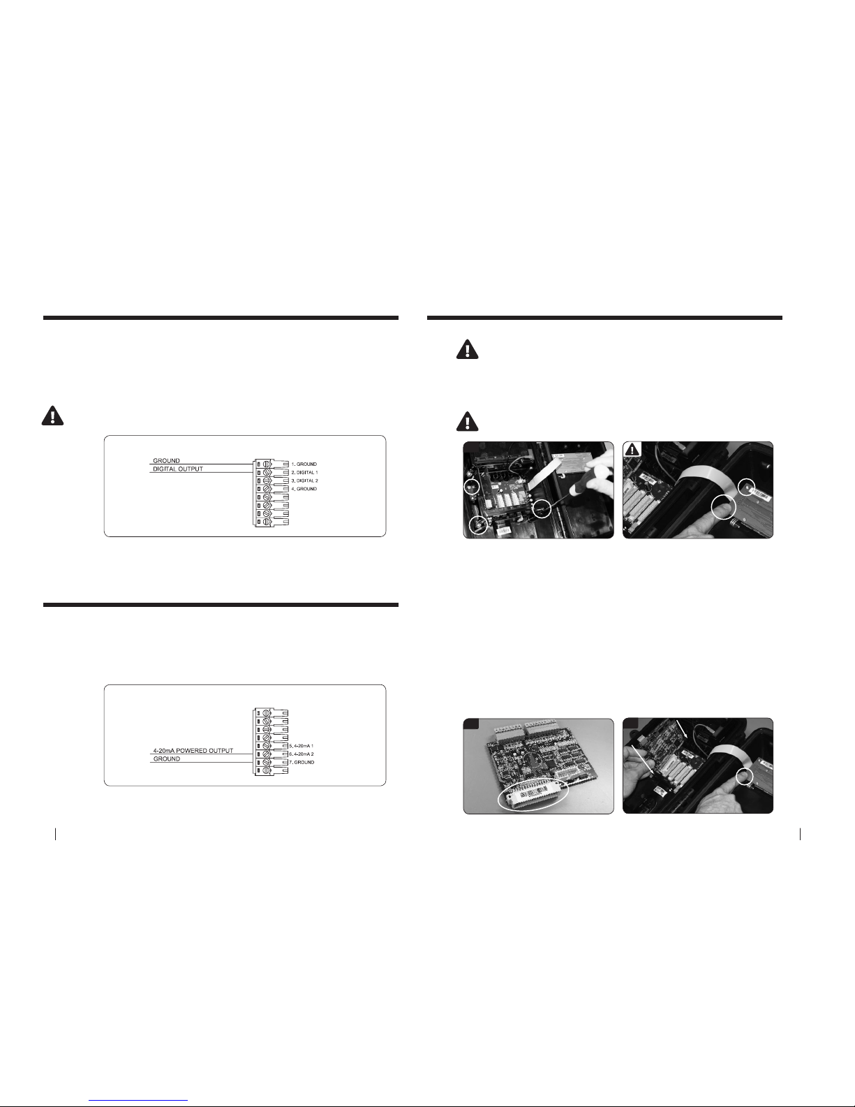
DIGITAL OUTPUT DIAGRAM
DIGITAL OUTPUT DIAGRAM
4-20mA OUTPUT DIAGRAM
10.0 Wiring digital outputs
11.0 Wiring analogue outputs
Digital Output
Each I/O card provides up to two digital outputs for sending pulses to
devices such as water samplers and/or data loggers. The digital output
terminals available on each I/O card are shown in the diagram below.
4-20mA Output:
Each I/O card provides up to two 4-20mA outputs for sending signals to
devices such as SCADA systems and/or PLC’s. The 4-20mA output terminals
available on each I/O card are shown in the diagram below.
NOTE: The pulse output consists of a 50 millisecond pulse with a 50
millisecond space between pulses
12.0 Installing additional cards
Users are advised to download data and stop the HM 3000 prior
to installing additional cards
1. Open the Series3 enclosure and remove the three screws (using a #2
Phillips screwdriver) fastening the PCB clamping bracket. Take care not to drop
screws in the box as damage may occur to the circuitry.
IMPORTANT: Before removing card from packaging you MUST earth
yourself by touching one of the screws on the display module
1
3
3. Remove the MACE Series3 card from its packaging. Position the new card
in your hand such that the large cream 48-pin connector is facing down and
aligned with the mating connector on the backplane PCB.
4. Earth yourself again. Your nger must remain earthed on the screw
whilst carefully inserting the card into any spare slot. Take care to align the
pins of the two connectors together. There is a slot at the top of the card
area that helps the alignment process. Ensure that the card is contained
within this slot and press down rmly to ensure that it is seated fully.
5. Replace the PCB clamping bracket ensuring that the slots in the underside
of the bracket are aligned with the tops of all the cards. Fix the bracket into
place with the 3 screws. DO NOT over tighten the screws.
6. Connect to the instrument with a PC and congure the card using FloCom+
as detailed in the software section of this manual.
4
20 SeCtion a HARDWARE MANUAL
RetuRn to toC
RetuRn to toC
MaCe HydR oMaCe 3000 PROD UCT MANUA L 21
13.0 Installing a Series3 FloSI card
The Flo Series Serial Interface (FloSI) is an optional upgrade module for
Flo Series3 devices. The FloSI provides unconditional polling access to the
most recent user congured measurement results of Flo Series3 devices.
The FloSI requires no routine maintenance and has no user serviceable
components.
Conguration of the FloSI requires MACE Flocom+ software and successful
PC communications with a MACE Flo Series3 device. The FloSI conguration
settings are available from the settings menu of Flocom+ as described in the
software section of this Manual.
Installing the FloSI Card
Install the FloSI card as per the procedure outlined in the previous chapter
12.0 Installing additional cards.
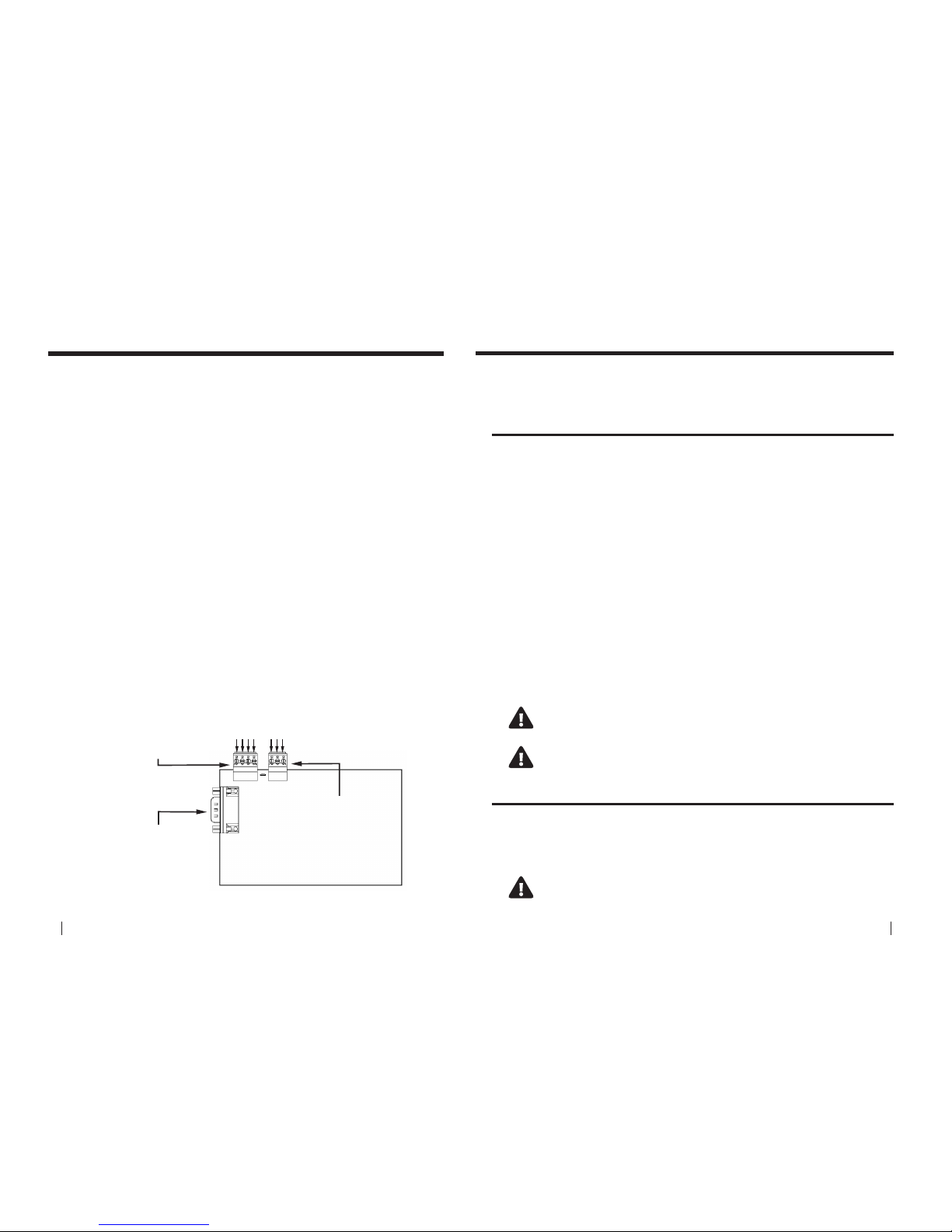
Wiring the FloSI
After installing the card, connect it to the remote device using either:
1. The 9-pin d-connector (RS232, ASCII or RS232 ModBUS) for RS232;
2. The 4-way terminal block for RS485 ModBUS mode;
3. The 3-way terminal block for SDI-12 mode.
Pin out details for the various connectors are printed on the back of the FloSI
card and below:
RS232
Pin 2 – Transmit Data (TxD)
Pin 3 – Receive Data (RxD)
Pin 5 – Ground (GND)
Pin 7 – Ready to Send (RTS)
Pin 8 – Clear to Send (CTS)
FloSI Card - Diagram
RS485
Pin 1 – Ground
Pin 2 - D1
Pin 3 - D0
Pin 4 - (+12V Out)
SDI-12
Pin 1 – Ground
Pin 2 - Data
Pin 3 - (+12V Out)
1234
123
14.0 Maintenance
Depending on the physical location and the type of sensors being monitored,
the HydroMace 3000 may require regular maintenance. Should the instrument
require servicing, it must be returned to your vendor.
14.1 Battery maintenance
The HydroMace 3000 internal battery, if kept fully charged should last many years.
However, if the battery remains at for an extended time, it may be damaged and
should be replaced. Contact your vendor for a replacement battery.
14.1.1 Removing the damaged/at battery
1. Disconnect the battery cable assembly from the backplane board.
2. Carefully hold the battery in position.
3. Use a #2 Phillips head screwdriver to remove the three screws which fasten the
battery bracket to the main enclosure.
4. Carefully remove the battery from the main enclosure.
5. Disconnect the battery cable from the battery terminals.
14.1.2 Installing the new battery
1. Connect the battery cable to the new battery, with the red lead to the positive
terminal of the battery and the black lead to the negative terminal.
2. Place the battery in the main enclosure and hold it in place.
3. Secure the new battery in place using the battery bracket and three screws.
4. Tighten all three screws.
5. Reconnect the battery cable assembly to the backplane board.
Damage to the HydroMace 3000 caused by incorrect battery
replacement will void the warranty
Using a battery that is not approved MAY damage the
HydroMace 3000 and void the warranty
14.2 Solar panel maintenance
The solar panel should be checked regularly for build up of solids such as dust
and bird droppings. These type of build-ups can aect the performance of the
solar panel and result in a decrease of the charge that is received by the internal
battery. The solar panel should be cleaned with a wet brush or rag.
Do not use steel bristle brushes that may cause damage to the glass of
the solar panel
 Loading...