

mabe PVUS930, PVUS936 Service Manual
Models:
PVUS930
PVUS936
SERVICE Manual
RANGE HOOD CONTENTS
• Safety precautions
• Distance from the cooktop
• Technical specifi cations
• Technical data
• Parts supplied
• Non-return valve - parts supplied
• Aluminium panel / charcoal fi lter
• Installation
• Control drawing
• Touch control
• Bulbs
• Transformer
• Power board
• Electrical assembly
• Wiring diagram
• Motor
• Condenser
• Exploded view
• Spare parts list
• Troubleshooting
29-5829


- 3 -
SUMMARY
1. Safety precautions ........................................................................................................................4
2. Distance from the cooktop ............................................................................................................7
3. Technical specifications ................................................................................................................8
4. Technical data ...............................................................................................................................9
5. Parts supplied .............................................................................................................................10
6. Non-return valve (exhaust damper) - parts supplied ...................................................................11
7. Aluminium panel / charcoal filter .................................................................................................12
7.1 replacing the aluminum panel
7.2 replacing the charcoal filter
8. Installation ...................................................................................................................................13
8.1 prepare the appliance for mounting 8.1
8.2 mounting the hood in the lower part of the cabinet
8.3 mounting the hood on the wall
8.4 installing the charcoal filters and aluminum panels
9. Control drawing ..........................................................................................................................19
9.1 configuration
9.2 technical drawing of control board
10. Touch control. ..............................................................................................................................21
10.1 replacing the touch control
11. Bulbs ...........................................................................................................................................23
11.1 replacing the halogen bulbs
11.2 replacing the halogen bulbs socket
12. Transformer .................................................................................................................................25
12.1 replacing the transformer
13. Power board ................................................................................................................................26
13.1 replacing the power board
14. Electrical assembly .....................................................................................................................28
15. Wiring diagram ............................................................................................................................29
16. Motor ...........................................................................................................................................30
16.1 replacing the motor
17. Condenser ..................................................................................................................................34
17.1 replacing the condenser
18. Exploded view .............................................................................................................................35
19. Spare parts list ............................................................................................................................36
20. Troubleshooting ...........................................................................................................................37

- 4 -
Before connecting the model to the electricity
network:
- Check the data plate (positioned inside the
appliance) to ascertain that the voltage and power
correspond to the supply circuit. If in doubt ask a
qualifi ed electrician.
- If the power supply cable is damaged, it must be
replace
d with another cable or a special assembly,
which may
be obtained direct from the manufacturer.
- This device must be connected to the supply
circuit through a hardwired spur protected by 3A
fuse.
WARNING !
In certain circumstances electrical appliances
may be a danger hazard.
A) Do not check the status of the filters while
the cooker hood is operating
B) Do not touch bulbs or adjacent areas, during
or straight after prolonged use of the lighting
installation
C) Flambè (Flamed) cooking is prohibited
underneath the cooker hood
D) Avoid free flame, as it is damaging for the
filters and a fire hazard
E) Constantly check food frying to avoid that
the overheated oil may become a fire hazard
F) Disconnect the electrical plug prior to any
maintenance
G) This appliance is not intended for use by
young children or infirm persons without
supervision
H) Young children should be supervised to
ensure they do not play with the appliance
I) There shall be adequate ventilation of the
room when the rangehood is used at the same
time as appliances burning gas or other fuels
L) There is a risk of fire if cleaning is not carried
out in accordance with the instructions
M) Please use a dedicated plug receptacle for
power plug
N) Please don’t operate the hood when there is
a flame on the dishes or frying pan
O) Please don’t touch the product or operate
the switch with wet hands
P) Please don’t wipe off the hood with the
chemicals when cleaning.
The symbol
on the product or on the accompanying paperwork indicates that the appliance
should not be treated as domestic waste, but
should be delivered to a suitable electric and
electronic appliance recycling collection point.
Follow local guidelines when disposing of waste.
For more information on the treatment, re-use and
recycling of this product, please contact your local
authority, domestic waste collection service or the
shop where the appliance was purchased.
Assembly and electrical connections must be
carried out by specialised personnel.
• Electric Connection
The connection to the mains is carried out as
follows:
BLACK = L line
WHITE = N neutral
GREEN/YELLOW = G ground
Connect to a junction box suitable for the electrical
load indicated on the description label.
An omnipolar switch with a minimum opening of
3mm between contacts, in line with the electrical
load and local standards, must be placed between
the appliance and the network in the case of direct
connection to the electrical network.
Before proceeding with the assembly operations,
remove the anti-grease filter(s) so that the unit is
easier to handle.
In the case of assembly of the appliance in the
venting version prepare the hole for evacuation of
the air.
• We recommend the use of an air exhaust tube
which has the same diameter as the air exhaust
outlet hole. If a pipe with a smaller diameter is
used, the efficiency of the product may be reduced
and its operation may become noisier.
Safety precautions
- 5 -
Safety precautions
• We recommend that the cooker hood is switched
on before any food is cooked. We also recommend
that the appliance is left running for 15 minutes
after the food is cooked, in order to thoroughly
eliminate all contaminated air.
The effective performance of the cooker hood
depends on constant maintenance; the antigrease filter and the active carbon filter both
require special attention.
• The anti-grease filter is used to trap any grease
particles suspended in the air, therefore is subject
to saturation (the time it takes for the filter to
become saturated depends on the way in which
the appliance is used).
- To prevent potential fi re hazards, the anti-grease
fi lters should be washed a minimum of every
2 months (it is possible to use the dishwasher for
this task).
- After a few washes, the colour of the fi lters may
change. This does not mean they have to be
replaced.
If the replacement and washing instructions are
not followed, the anti-grease fi lters may present a
fi re hazard.
• The acrylic filter, which is found resting on the
grille, should be replaced when the text, visible
through the grille, changes colour and the ink
spreads; the new filter should be fitted in such a
way that the text can be seen through the grille
from outside the cooker hood.
• If the filters do not have any text on them, or if
metal filters or aluminium panel filters are used,
they should be washed every 2 months in order to
prevent the risk of fire.
To wash the filters, proceed as follows:
- Remove the filter from the grille and wash it using
a solution of water and neutral liquid detergent,
leaving the dirt to soften.
- Rinse thoroughly with warm water and leave to
dry.
• The active carbon filters are used to purify the
air which is released back into the room. The
filters are not washable or re-usable and must
be replaced at least once every four months. The
active carbon filter saturation level depends on the
frequency with which the appliance is used, the
type of cooking performed and the regularity with
which the anti-grease filters are cleaned.
• Remove build-up from the fan and other surfaces
of the cooker hood regularly using a cloth moistened
with denatured alcohol or non-abrasive neutral liquid
detergent.
CAUTION!
Wear gloves during the installation of the product
otherwise injury at ngers could happen by sharp
edges.
- 6 -
Safety precautions
WARNING !
• Take care when the cooker hood is operating simultaneously with an open fireplace or burner that
depend on the air in the environment and are supplied by other than electrical energy, as the cooker
hood removes the air from the environment which a burner or fireplace need for combustion. The
negative pressure in the environment must not exceed 4Pa (0.016 WC.). Provide adequate ventilation
in the environment for a safe operation of the cooker hood. Follow the local laws applicable for external
air evacuation.
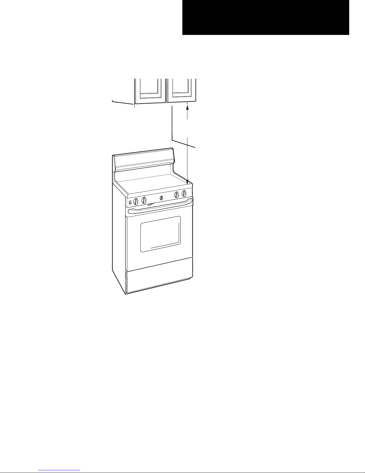
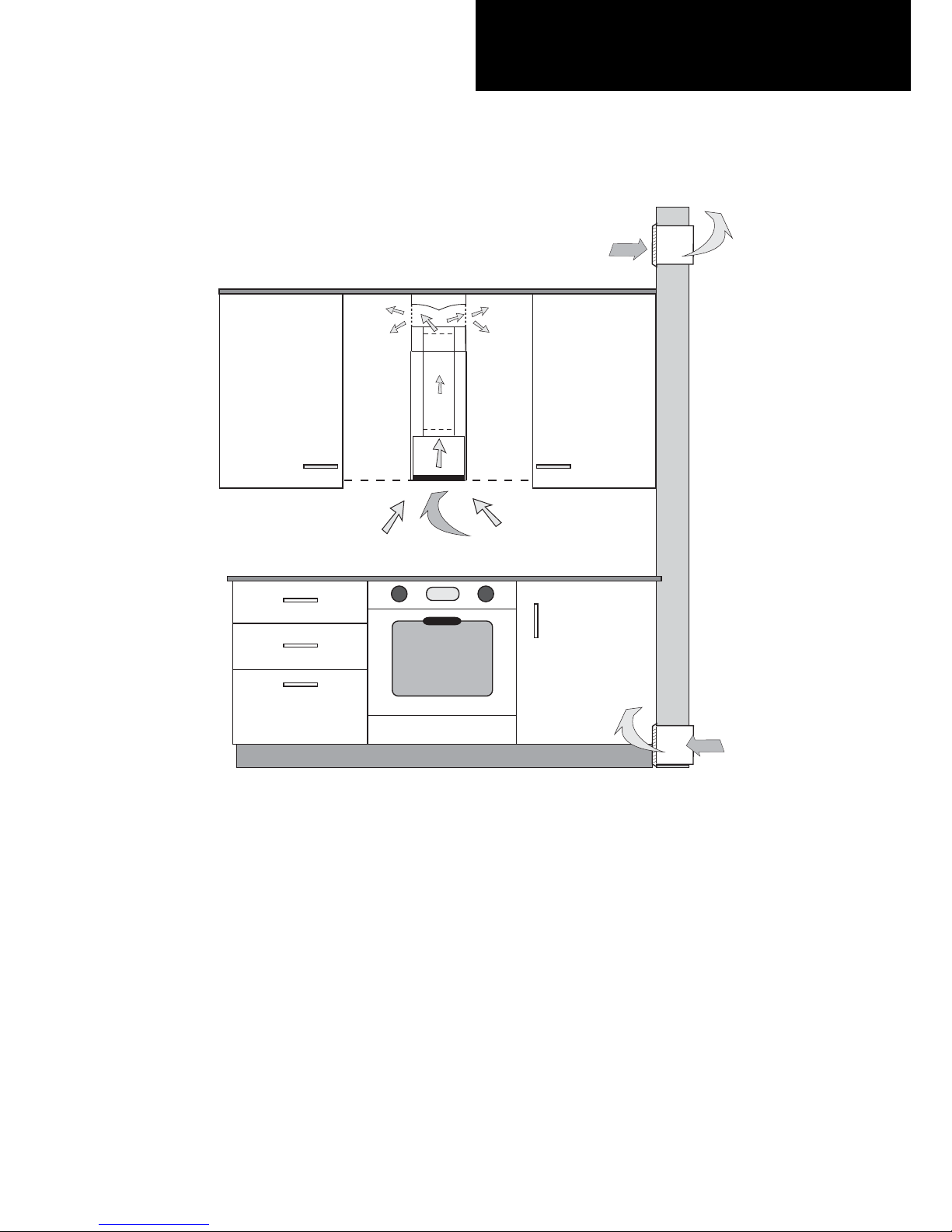
- 7 -
Distance from the cooktop
• The minimum distance between the support surfaces of the cooking pots on the cooker top and the lowest
part of the cooker hood must be at least 30’’.
If a venting tube composed of two parts is used, the upper part must be placed outside the lower part.
Do not connect the cooker hood exhaust to the same conductor used to circulate hot air or for evacuating
fumes from other appliances generated by other than an electrical source.
30”
min.
- 8 -
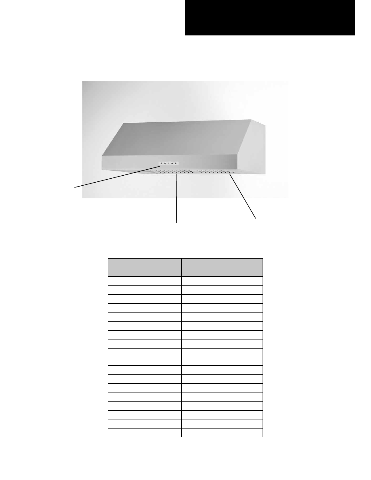
Technical specifi cations
CONTROLS
ALUMINIUM PANELS
LIGHT
MODELS
PVUS930
PVUS936
Size 30’’- 36’’
Finish St.steel
Motor HB4
Extracting power (CFM) 600
Voltage 110-120V ~ 60Hz
Motor power consumption 1 x 420 W
Product certifi cation UL
Product class Class I
Type model PVUS930S1SV -
PVUS936S1SV
Air outlet diameter (mm) 150
Controls Touch Control
Speeds 3+1
Version Duct out
Filters Aluminium panels
Charcoal Filters 2 Circular fi lters
Bulbs 2 x 20 W Halogen lamps
Weight Gross 22,7 - 23,9 Kg
- 9 -
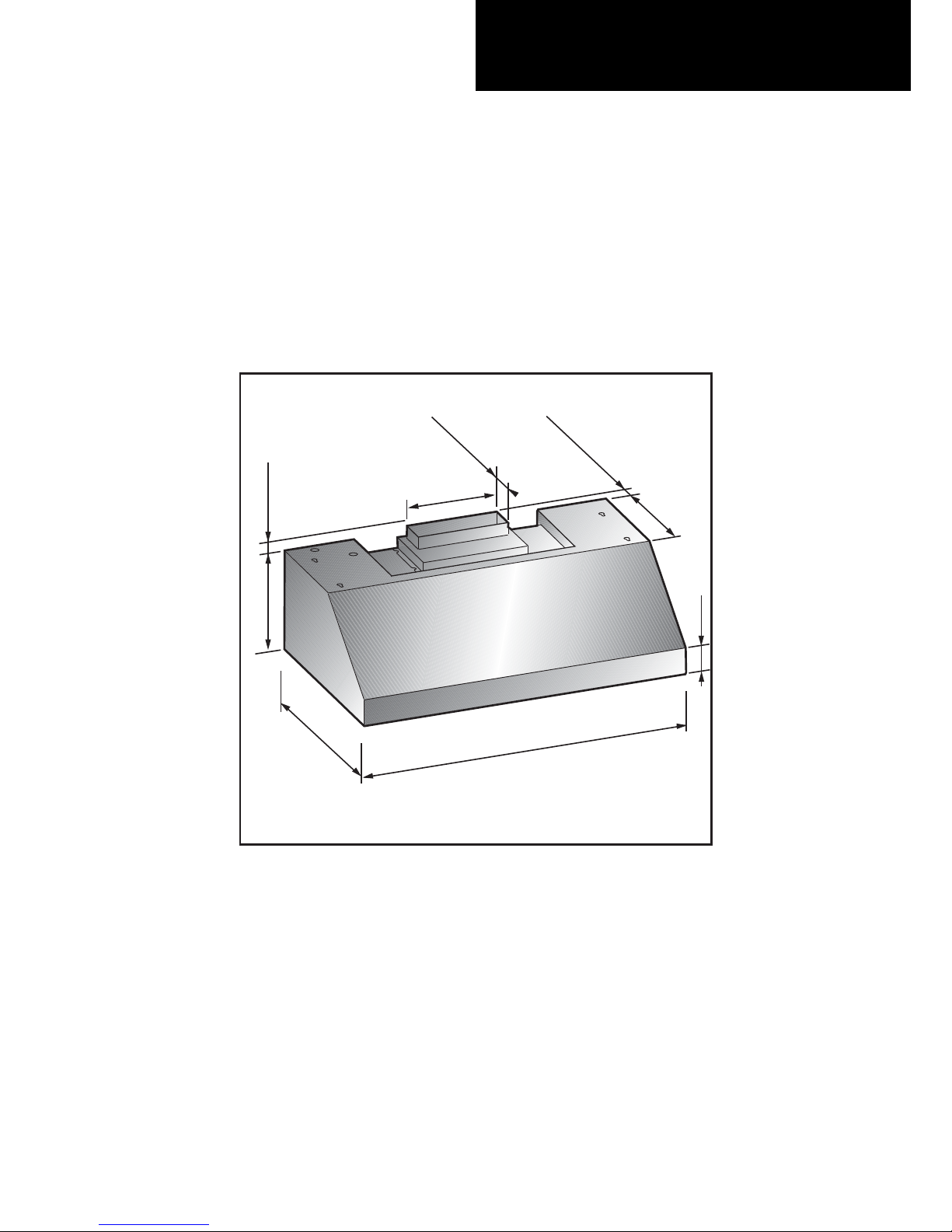
Technical data
22''
29-15/16'' - 35-15/16''
11''
1
-3/8
''
10''
1-13/16''
3
''
12''
3-1/4''
- 10 -
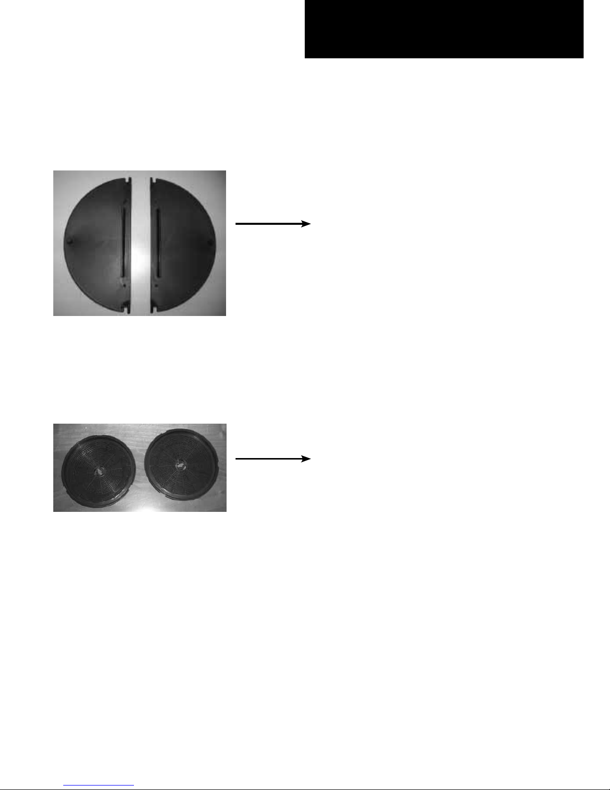
Parts supplied
NON RETURN VALVE
(exhaust damper)
2 CHARCOAL FILTERS
(air recirculation option only)
- 11 -
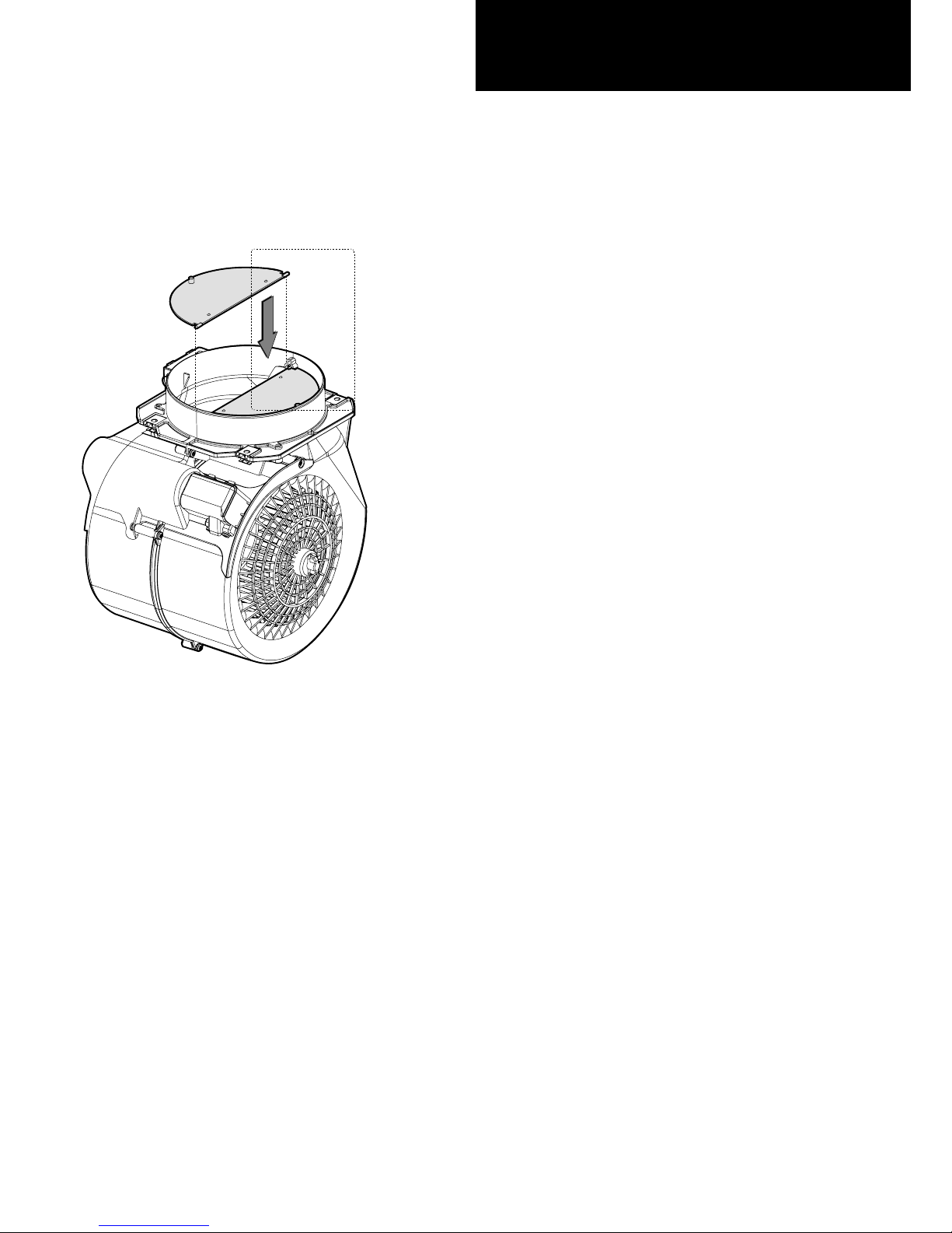
Non-return valve
parts supplied
The non-return valve (exhaust damper) is
recommended when the appliance is installed in
the extracting version, to prevent cold air blowing
back in from outside.
The valve is made up of two parts which must be
fixed to the air outlet flange on the motor assembly
If the appliance is installed in the recirculation filtering
version, the non-return valve is not necessary.
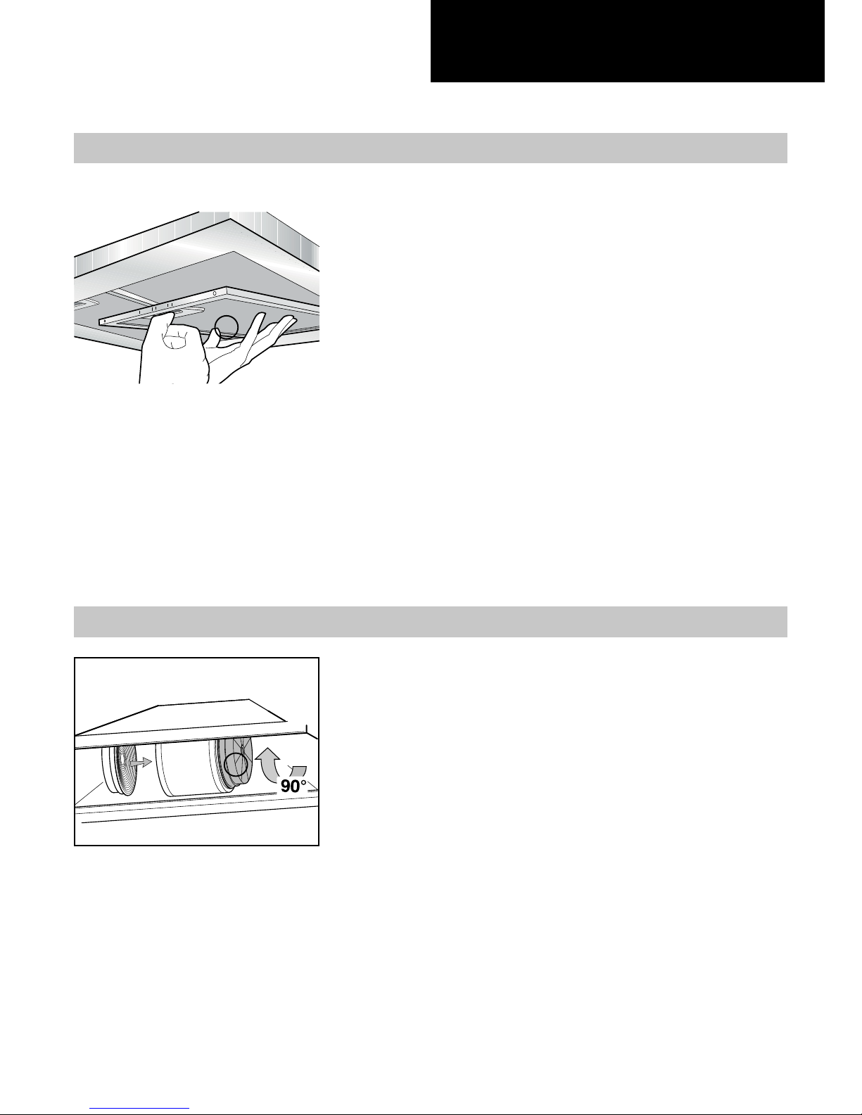
- 12 -
Aluminium panel
Charcoal fi lter
The metal filters and/or aluminium panel are also dishwasher
safe. If the filters are made using aluminium, or if an aluminium
panel is used, after a few washes the colour may change.
This does not mean they have to be replaced.
If the replacement and washing instructions are not followed,
the anti-grease filters may present a fire hazard.
To replace the aluminium panels, simply operate the handle
(a) provided for the purpose, as illustrated in the drawing.
The active carbon filters are used to purify the air which is
released back into the room. The filters are not washable
or re-usable and must be replaced at least once every four
months. The active carbon filter saturation level depends on
the frequency with which the appliance is used, the type of
cooking performed and the regularity with which the antigrease filters are cleaned.
To replace the active charcoal filters, simply operate the
handle provided for the purpose, as illustrated in the drawing.
Replacing the aluminium panel (a) 7.1
Replacing the charcoal fi lter (b) 7.2 (on some models)
a
b
 Loading...