

mabe PTAN9150MWW, PTAN9250MWS, PTAN9350MWS, PTAN9450MWS, PTAN9455MGG Technical Service Manual
Page 1
Technical Service Guide
New Top Load Washer
Model Number:
PTAN9150MWW, PTAN9250MWS, PTAN9350MWS, PTAN9450MWS, PTAN9455MGG
Mabe Canada
Robert Gauthier
Training & Technical Support
Pub #10-MAN-AW-02
DATE: May 2011
1
Page 2

IMPORTANT SAFETY NOTICE
The information in this service guide is intended for use
by individuals possessing adequate backgrounds of
electrical, electronic, and mechanical experience.
Any attempt to repair a major appliance may result in
personal injury and property damage. the manufacturer
or seller cannot be responsible for the interpretation of
this information, nor can it assume any liability in
connection with its use.
WARNING
To avoid personal injury, disconnect power before
servicing this product . If electrical power is required for
diagnosis or test purposes, disconnect the power
immediately after performing the necessary checks.
RECONNECT ALL GROUNDING DEVICES
If grounding wires, screws, straps, clips, nuts, or
washers used to complete a path to ground are removed
for service, they must be returned to their original
position and properly fastened.
mabe Canada
2
Page 3

Table of Contents
Nomenclature……………………………………………………………………….. ……...…………………………....4
Introduction………………………………………………………………………….. …………………………………...5
About the control panel…………………………………………………………… ……………………………….6,7,8
Installation…………………………………………………………………………… …………………………………...9
Washer Warranty…………………………………………………………………… ………………………………….10
Drawer dispenser…………………………………………………………………... ………………………………….11
Loading the Washer……………………………………………………………….. ………………………………….12
Water consumption and cycle times……………………………………………. ………………………………….13
TM
HydroSoft
Infusor
Understand the consumer’s issue first……………………………………… … …………………………15, 16, 17
Wash Cycle Progression………………………………………………………….. ………………..18, 19, 20, 21, 22
Shower Rinse Progression ………………………………………………………. ………………………………….23
Deep Rinse Progression…………………………………………………………... ………………………………….24
Final Spin…………………………………………………………………………….. ………………………………….25
TM
Washer Tips…………………………………………….. ………………………………….14
Operating Cycles…………………………………………………………………… ………………………………….26
Component Locator Views……………………………………………………….. ……………………………..27, 28
How to remove the control panel, top, control board ………………………. ………… …………………..29, 30
Infusor Removal, transmission removal……………………………………….. …………………….31, 32, 33, 34
ATC Thermistor………………………………………………………… ………….. ………………………………….35
Water valves, Drain Pump, Wax Motor, Motor Sensor……………………… ……………………………...36, 37
Testing the Motor…………….…………………………………………………….. ………………………………….38
Shifter System………………………………………………………………………. ………………………………….39
Motor Sensor………………………………………………………………………... ………………………………….40
Lid Lock………………………………………………………………………………. …………………….41, 42, 43, 44
How to check the Programs Switch…………………………………………….. ………………………………….45
How to check the Selector Switch……………………………………………… ………………………………….46
Wiring Diagram……………………………………………………………………... ………………………………….47
How to Enter or Exit to Service Mode………………………………………….. ………………………………….48
Component testing (knob position)…………………………………………….. ………………………………….49
Error and Fault Code………………………………………………………………. ………………………………….50
………………………………….51
Pressure Sensor……………………………………………………………………. ………………………………….52
Circuit Board Connections……………………………………………………….. ……………………………..53, 54
3
Page 4
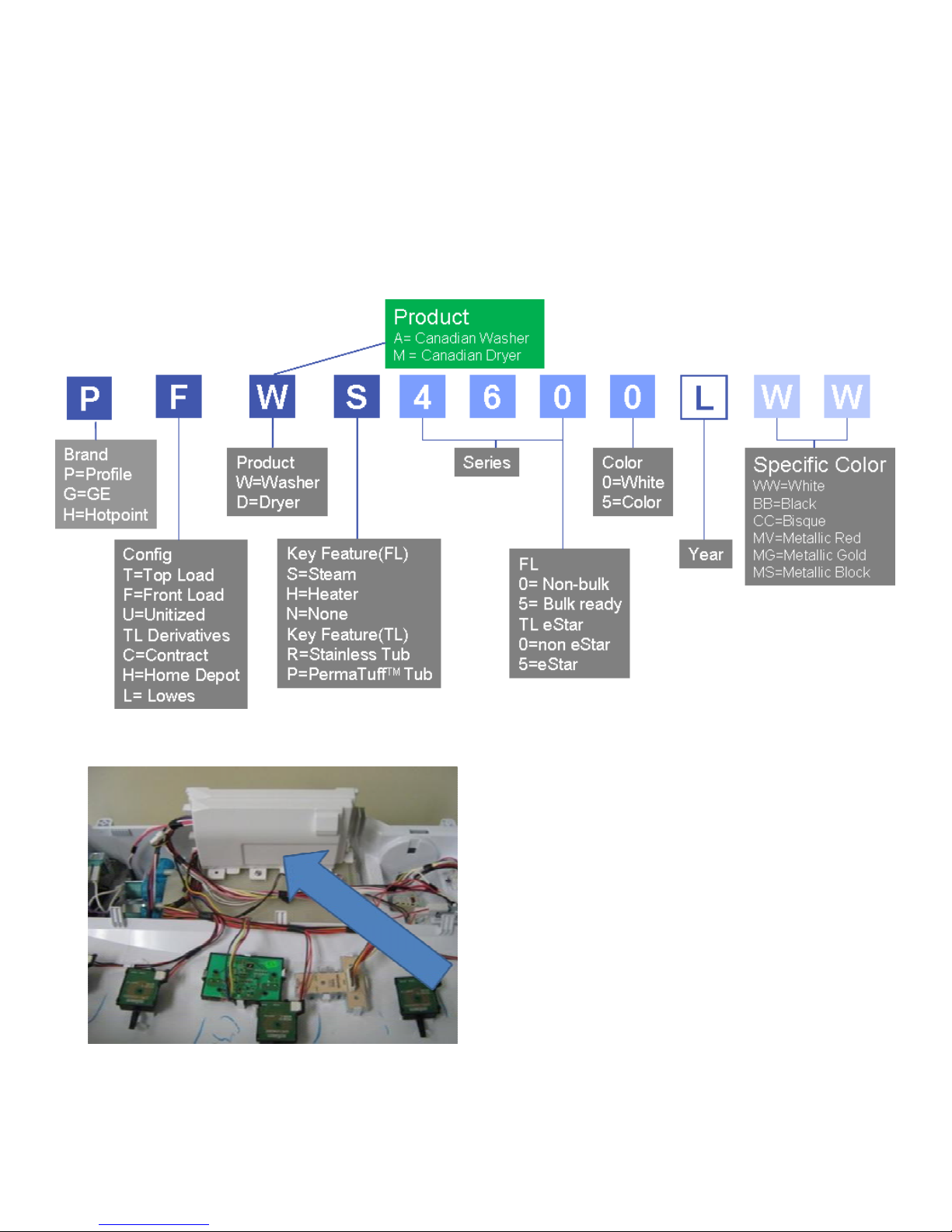
2010 Clothes Care Nomenclature Washer
Location of mini-manual
4
Page 5

Introduction
Feature Current models New models
Wash action Agitator Impeller
Washer cover Plastic Plastic or glass
Wash temperatures 3 settings 3 to 5 settings + ATC
Rinse system Normal Shower + Deep rinse
Drive system
Transmission with solenoid
Safety
Lid lock w/mech switch (2
minutes to open)
Controls Electronic w/knobs
Service
Only 1 error code, no service mode
Transmission with wax
switch
Lid lock w/instantaneous
switch
Electronic w/knobs and 3
digit display
Multiple error codes, full
service and demo mode
5
Page 6
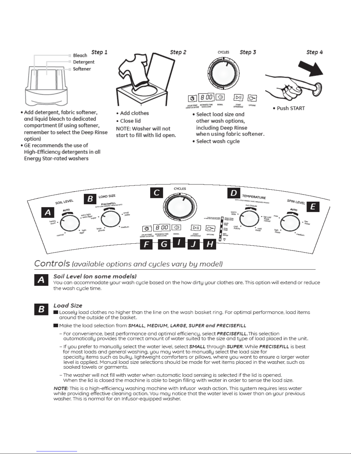
Quick Start Guide
About the control panel.
6
Page 7
7
Page 8
8
Page 9
Installation
INSTALLATION REQUIREMENTS
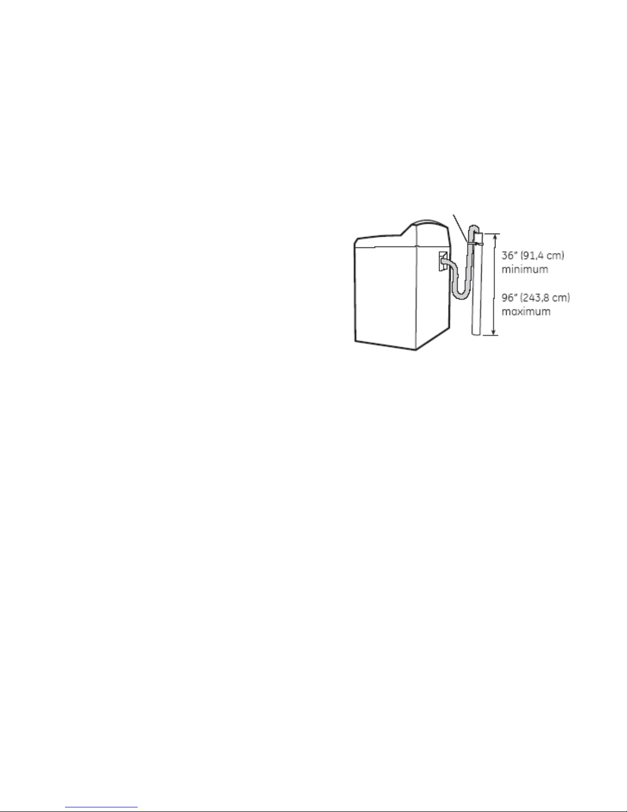
DRAINAGE
A vertical standpipe with an internal diameter of 1-1/2”
(3.8 cm) is required. The standpipe height above the
floor must be:
Minimum height: 36” (91,4 cm)
Maximum height: 96” (243,8 cm)
Insert the drain hose into the standpipe and secure it
with the cable tie located inside the accessories bag.
The standpipe must be open to the atmosphere (there
must be an air gap around the drain hose).
If you need to extend the lenght of the drain hose to
reach
your standpipe, please contact your local parts store to
purchase the recommended drain hose extension for
your washer.
Cable tie
WATER SUPPLY REQUIREMENTS
Hot and cold water faucets MUST be installed within 42”(107 cm) of your washer’s water inlet. The
faucets MUST be 3/4” (1.9 cm) garden hose-type so inlet hoses can be connected.
Water pressure MUST be between 10 and 100 pounds per square inch.
Your water department can advise you of your water pressure.
The hot water temperature should be set to deliver water at 120° to 140°F (48° to 60°C).
Page 10
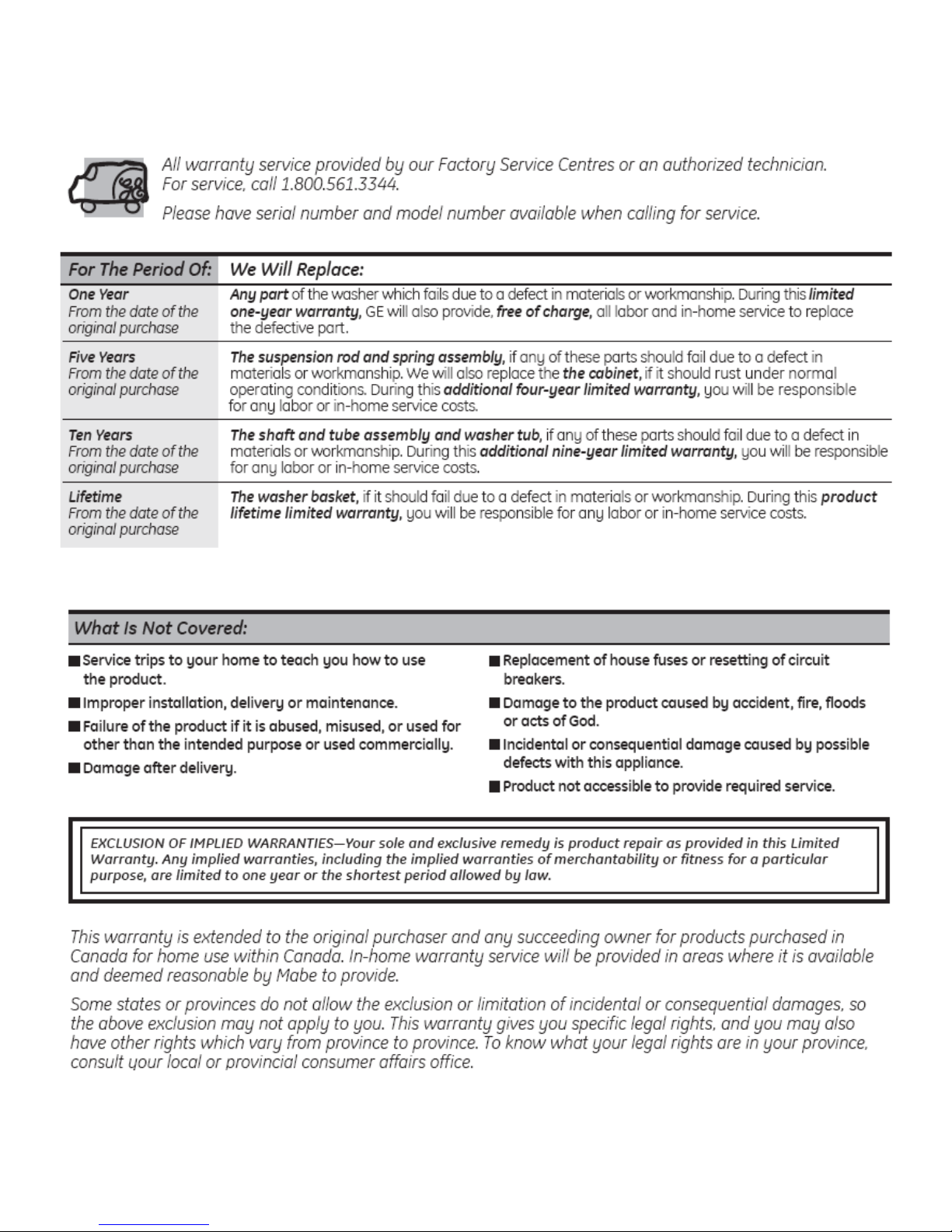
Washer Warranty
Page 11
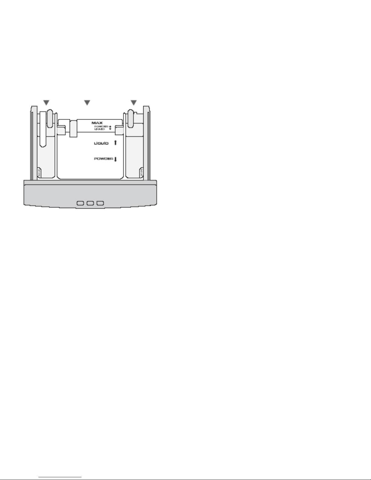
Flow Logic automatic drawer dispenser.
Your washer is equipped with an automatic dispensing system, comprised of a drawer with 3
compartments:
Bleach Detergent Softener
Liquid bleach
Pour liquid bleach into the designated compartment without filling beyond the mark.
Check clothing care labels for special instructions. Use
less for smaller loads.
Do not dilute bleach. Bleach will be added automatically
diluted to avoid direct contact with the clothes. Use only
this compartment, do not add bleach directly onto clothes.
IMPORTANT:
To avoid any potential leftover bleach mixture being dispensed in a subsequent cycle, it is strongly recommended
to verify that the bleach compartment of the dispenser is
free of any leftover bleach and water mixture. If there is
some leftover bleach mixture, please empty the contents
to avoid any damage to clothes that cannot tolerate
bleach
.
Detergent
Add the amount of powder or liquid low suds detergent in the compartment, as recommended by the manufacturer and according to the size of the
load. You should not put the detergent directly on the clothes in the washer.
· For powder detergent: Install the divider in the front position. Put the detergent selection blue wall, that is located at the end of the dispenser, in
the front position
· For liquid detergent: Install the divider in the back position. Put the detergent selection blue wall , that is located at the end of the dispenser, at
the back position.
Place the amount of liquid detergent without exceeding the maximum level indicated.
Fabric Softener
Pour fabric softener into the designated compartment without filling beyond the mark.
Note: in order for the fabric softener to be dispensed you must select the DEEP RINSE option. Please refer to the Options
section of this manual.
11
Page 12
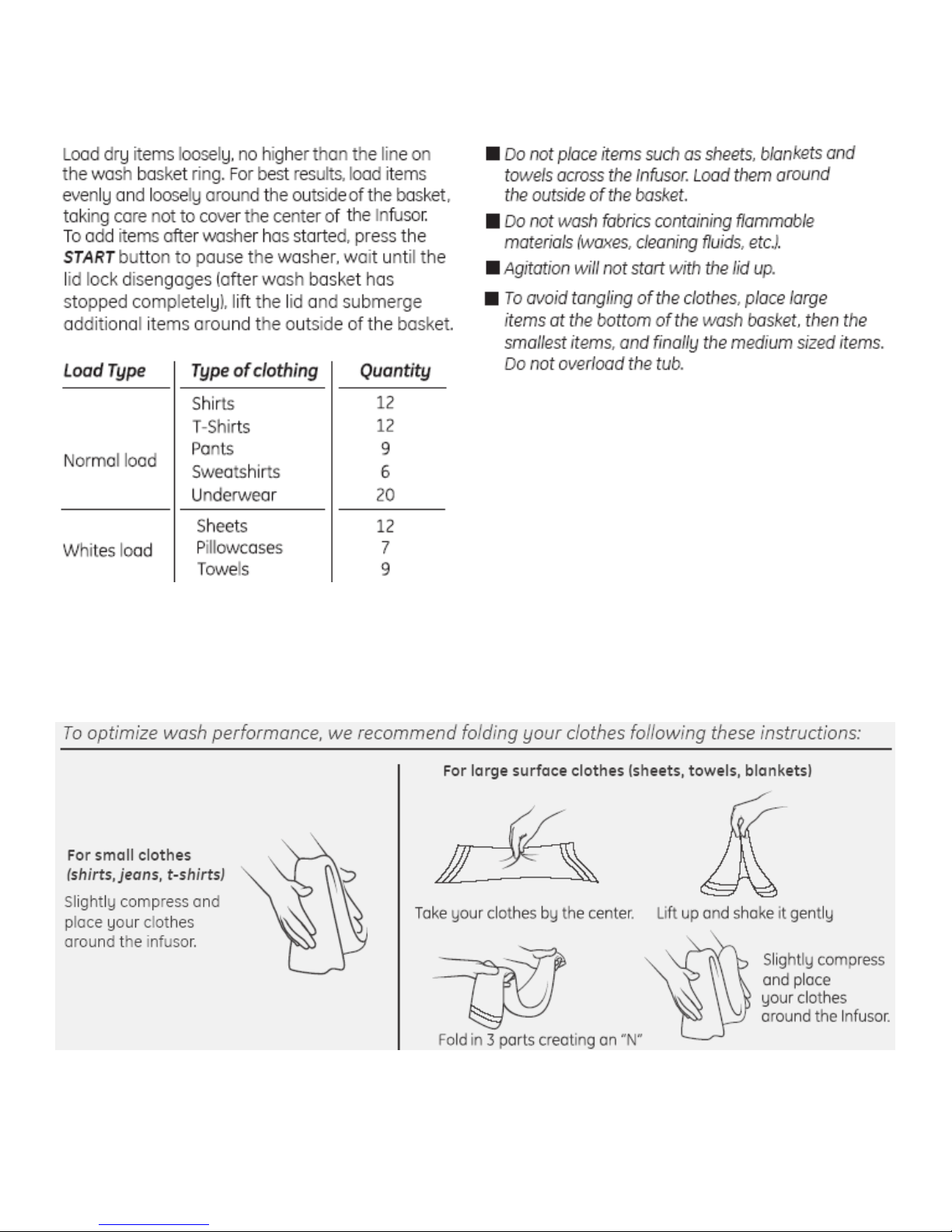
Loading the Washer
12
Page 13
Water Level
Water consumption
Approx
Wash Rinse Total
Load Size
Gal. Lt. Gal. Lt. Gal. Lt.
Max Level
High Level
Medium Level
12 — 16 lb 13.74 52 8.98 34 22.72 86
9 — 11 lb 12.15 46 8.98 34 21.14 80
6 — 8 lb 10.30 39 6.08 23 16.38 62
Cycle times
Programs Wash Final Spin
Heavy Soil
Whites
colors
Jeans
18 min. 10 min.
18 min. 16 min.
14 min. 2 min.
13 min. 5 min.
Total
1:17
1:21
1:12
1:09
Delicates
Wool
Towels / Linen
Bulky items
Quick Wash
Wash & Spin
6 min. 2 min.
8 min.
13 min. 5 min.
11 min. 5 min.
3min. 3 min.
N/A 6 min.
Only 3 spin ramps
13
:59
:38
1:09
1:02
:53
:10
Page 14

TM
HydroSoft
INTRODUCTION
TM
HydroSoft
technology provides excellent cleaning. Infusor models are ENERGY STAR® qualified
using only 23 gallons of water per (super) load compared to 48 gallons for a similar
load with a standard machine .
High efficiency (HE) detergent is required with Infusor models. Liquid HE detergents
dissolve faster in water. For best performance, load the machine by adding liquid HE
detergent first. Add the dirtiest clothes around, but not covering, the center of the
Infusor, then add the remaining clothes. Do not load clothes higher than the line
indicated on the balance ring at the top of the wash basket. Insert items as per the
Use and Care. Select proper load size, water temperatures, and rinse options. Use a
fabric softener for better performance
model washers use an InfusorTM, not a traditional agitator. Infusor wash
Infusor
.
TM
Washer Tips
Infusor models turn the washer basket at slow speed during fill to allow the fill funnel
to evenly coat the wash load with water and push clothes to the bottom. The lid will be
locked during the fill to evenly wet the clothes. If you wish to add or remove an item,
press the Start/Pause button to pause the washer. The lid will unlock once the basket
has come to a complete stop. This is for your safety.
Infusor models spin at up to 700 RPM. This extracts more water during the spin cycle,
compared to a standard machine, and minimizes drying time. If wrinkling is a concern,
use a lower spin level to shorten the spin duration.
Given that Infusor washers operate differently from standard top-load machines,
consumers may comment on lint, lower water levels, washing differently than
expected, spots on clothing, wrinkling, water temperature, vibrating/shaking, too-wet
clothes, unusual sounds, or loose tub/basket.
Take the time to listen carefully and fully understand the consumer’s specific issue
before proceeding. Address the appropriate issue today to avoid a return service call.
14
Page 15

UNDERSTAND THE CONSUMER’S ISSUE FIRST
1. Lint
Do not overload the washer. Use the Deep Rinse option, adding more water, to
reduce lint.
2. Not filling or low water level
Infusor models are designed to use less water and are ENERGY STAR® qualified.
During the wash cycle, water may not entirely cover the top of clothes. If Super size
load is selected, the water level will be just at the top of the Infusor.
Check for water supply hoses pushed up tightly against a wall. This condition can
affect the position of the fill funnel so that the water spray isn’t correct during fill. Pull
the washer away from the wall a little to correct.
Water pressure and water flow are critical to washer fill. The washer will not fill to the
proper level with a water pressure less than 20 PSI or with a blocked valve inlet
screen or other flow restriction.
The fill volume on the Small setting is 9 gallons. The water level will measure
approximately 5 inches above the bottom of the basket
..
Note: Measured water levels are approximate and can vary plus or minus 1 inch.
On the Super setting, the fill volume is 14 gallons. The water level will measure
approximately 8 inches above the bottom of the basket. With Super setting, the water
will come up to the top of the Infusor.
15
Page 16

All models have the PreciseFill Automatic Load Sensing feature. When PreciseFill is
selected, the machine determines fill time by sensing the load size. The Precise Fill
pressure switch minimum level setpoint. The lower level setpoint is attained at
approximately 1 inch of water depth, at which point the washer will start sensing the
load size and determine the optimal amount of water required and corresponding
water level.
Use the Deep Rinse option to add more water during rinse.
3. Washing differently than expected
Load the basket with similar weight items around the sides of the basket.
Overloading the washer can lead to poor cleaning performance.
Check for water supply hoses pushed up tightly against a wall. This can affect the
position of the fill funnel so that water spray isn’t correct during fill. Pull the washer
away from the wall a little to correct.
4. Spots on clothing
Usually caused by too much HE detergent; use less. Use less HE detergent with
softer water. Clothing is cleaned when soapy water bonds to the dirt and is rinsed
away. Too much detergent can generate soapy foam that is difficult to rinse away.
To correct, run a couple of cycles empty with no soap to rinse the machine, and then
run a load with less HE detergent. Use the Deep Rinse option to add more water
during rinse. Check for possible siphoning condition.
5. Wrinkling
Do not overload the washer. Overloading can lead to poor cleaning performance and
increase wrinkling. Infusor models spin faster than standard top-load machines to
extract more water for faster drying and can cause more wrinkling. If wrinkling is a
concern, use the Deep Rinse option to add more water during rinse, and select a
lower spin level for less spin time.
16
Page 17

6. Water temperature
Energy-star requirements dictate that even on a hot setting, the washer will mix in
some cold water. If the home water supply pipes have a long run, are imbedded in a
concrete slab, and/or the washer is used during the winter months, it may take
longer for the first hot water to reach the washer. Run the hot water at a nearby
faucet to check water supply temperature.
7. Vibrating/shaking
Check for proper levelling. If only an occasional complaint, check for out-of-balance
load.
8. Too-wet clothes
If the final spin leaves clothes too wet, re-arrange the clothes to balance the load,
then run another drain and spin cycle.
9. Loose wash tub/basket
A loose basket is normal when the washer is idle. Infusor models do not use a
mechanical brake to prevent the basket from turning. The basket slows down on its
own and will normally come to a full stop in less than 2 minutes if spinning at full
speed.
17
Page 18

Wash Cycle Progression
Level detection/
Overload sensing
Clothes
arrangement
Fill to Minimum Wa-
ter Level
(Sensing Level)
Washer starts by sensing if basket is over loaded.
Washer executes pattern to set the
clothes previous to agitation in order to improve wash performance.
Water and detergent are admitted in
this stage between tub and basket; at
the same time water circulates intermittently 6 seconds each 45 seconds
detergent dilution.
Final Spin
Rinse
Rinse Fill
Load
Sensing
Fill to selected
level
Agitation
Intensive agitation pattern if
or 14.5 min.
Washer agitates to determine water
level matches clothes load and type of
clothes.
After sensing load washer fills if
more water is required.
Untangling
Soft agitation pattern for 3.5 min. in
order to detangle and balance
clothes previous to spin.
Intermediate Spin Pattern
consist of a series of
speed ramps until maximum speed is reached.
Intermediate
Spin
Drain
Drain the wash
liquid.
18
Page 19

Wash Cycle Progression (cont.)
Level
detection/
Takes 2 spins, measures time to reach a certain angle.
Estimates if load is greater than 17 lbs or not.
Overload
sensing
Clothes
arrangement
If load is greater than 17lbs, it bypasses the "load arrangement" phase and goes straight to the pre-fill portion.
Washer executes pattern to distribute the clothes previous to
agitation in order to improve wash performance.
Load spins 2 times (CCW-CW), each time injecting cold water for 8
seconds.
• During each spin portion, the motor is successively activated (for
600 ms) and deactivated (for 2 seconds), intermittently spinning the
basket for a total of approx 10 seconds.
• Once the 10 seconds are over, unit goes into a full spin (at 700
RPM) and drain pump is activated for 10 seconds.
•After this, unit slows down to 100RPM.
Fill to Minimum
Water Level
(Sensing Level)
Water and detergent are admitted in this stage
directly into the basket.
• Water fill starts until the minimum water level is
reached.
• Water is at temp selected by consumer, regulated
by ATC thermistor.
19
Page 20

Wash Cycle Progression (cont.)
Washer agitates to determine if water level (as selected by con-
Load
Sensing
Fill to
selected
level
sumer) is appropriate for actual load size and type of clothes.
•After minimum water level is attained, washer senses if load is
greater than 17lbs (impeller only goes back and forth).
• Basket is spin intermittently by pulses (3 times CCW, then 3 times
CW) and water is injected via the dispenser, dispensing soap.
•If load is less than 17lbs, agitation can start after fill is complete to
desired level.
After load sensing, washer fills to desired level
• Washer fills to level selected by consumer or greater level if load
sensing determines selected load size is not sufficient.
Agitation
Washer agitates according to settings chosen by consumer,
between 14 and 18 minutes.
20
Page 21

Untangling
Wash Cycle Progression (cont.)
Soft agitation pattern for 3.5 min. in order to detangle and
balance clothes previous to spin.
• Washer agitates at different rate than main wash to set the
clothes in place for spin, for 3.5 minutes.
Drain
Intermedi-
ate Spin
Drain the wash water, until the minimum water level
setting is reached (no agitation).
Intermediate Spin pattern consist of a series of speed
ramps until maximum speed is reached.
• 30 seconds after "minimum"** water level is reached,
washer starts spinning basket doing 5 preliminary ramp ups
to ensure load is properly distributed and safe to bring up to
next spin level.
• The 6th spin level is the last of the Intermediate spin portion. If it's able to reach 600 rpm in the predetermined
amount of time, it keeps that speed for a total of 1.5 minutes.
** the "minimum" water level is actually lower than the
Minimum water level setting. It's approx. 1" of water in
the tub.
21
Page 22

Wash Cycle Progression (cont.)
Shower rinse is the normal rinse cycle. However, in some
instances the washer will go to a Deep Rinse instead:
•when fabric softener is used and customer has selected the
Deep Rinse option.
•on certain cycles such as Bulky Items.
•if the washer recognizes that a higher water level than the one
selected by the consumer is required to ensure proper operation of the washer.
The shower rinse is a timed fill, with water quantity dependant
Rinse Fill
on the water pressure regulated by water valve.
The number of Shower Rinses is determined by the water level
selected by the consumer and the actual water level as determined by the washer.
• If water level is Maximum or higher, washer does 3 rinse
blocks.
• If water level is High or lower, washer does 2 rinse blocks.
22
Page 23

Shower Rinse Progression
Fills with water up to level selected for
main wash (or adjusted by the washer if
insufficient)
Admits directly in the wash basket a predetermined water amount (approx. 3 gal @ 20
psi). Water amount is determined by time
(approx 40 seconds per block).
1
Basket stop
to 0 rpm
Waits until the basket
stops completely.
Water
Admission
Directly
no
Basket stop to 0
rpm
The water is sprayed on the
clothes while basket spins inter-
Clothes Saturation
(fresh water)
Drain &
Spin
Spin pattern
“between
rinse blocks”.
Rinse Blocks
Complete?
Number of rinse blocks depends on
selected load size:
2 blocks for Small, Med and Large
3 blocks for Super
Qty of water per block:
11 liters/2.9 gallons
Total Spin Time 16 min
Final Spin
End Cycle
23
Page 24

Deep Rinse Progression
Fills with water up to
level selected for
main wash (or adjusted by the washer.
1
Basket stop
to 0 rpm
Waits until the
The water is injected on the
clothes while basket spins
intermittently.
Water Ad-
mission
Directly
4 minutes of agitation. Agitation pattern same as wash
cycle.
Clothes
Saturation
(fresh water)
Agitation
basket stops
completely.
Drain &
Final Spin
End
Cycle
24
Page 25

Final Spin
• Washer start draining until "minimum" level is reached.
• After level is reached, washer starts spinning basket, ramping up to
400 RPM
• Washer then slows down to 230 RPM, then ramps up to spin speed
selected by consumer
• If washer CANNOT reach desired spin speed, motor shut off until
speed reaches 300 RPM
• After reaching 300 RPM, washer attempts to ramp up to final spin
speed again.
• If successful, spin lasts approx 16 minutes total
• If UNSUCCESSFUL at attaining desired spin speed BUT unit has only
performed 1 Deep Rinse, washer does another Deep Rinse cycle.
• If UNSUCCESSFUL at attaining desired spin speed AND unit has al-
ready performed 2 deep rinses, washer stops and an error code is
logged. (See codes page 55)
25
Page 26

26
Page 27

Component Locator Views
Hot Water
Valves
ATC (temperature control)
Dispenser water
Valves
Electronic Board
Pressure
Sensor
Lid
Switch
Lid Lock With Quick Release Dispenser
27
Page 28

Component Locator Views
Capacitor
Speed Sensor
Wax Motor
Transmission
Drain Pump
Motor
28
Page 29

HOW TO REMOVE THE CONTROL PANEL
1- Remove the two screws behind the control panel.
2– Lift back of console and tilt console towards machine front to free front
3 tabs.
29
Page 30

HOW TO REMOVE TOP
Remove the two screws behind the
washer. Pull the back of the top up
and forward to remove
Disconnect the 2 connectors (1) (2)
and remove the pressure switch hose
to remove the top.
..
(1)
Pressure switch hose
ELECTRONIC CONTROL (PCB)
The electronic control cover is held in place with plastic tabs.
(2)
The electronic control is held in place with two screws.
30
Page 31

INFUSOR REMOVAL
1- Remove the cap 2- Remove the bolt
3- Removing the Infusor
NOTE
Use a 3 ft by 3 ft floor protector under the washer to avoid damaging its components
or the floor when separating the tub assembly from the cabinet.
1- Remove the top (see page 24)
2- Remove the Infusor
TRANSMISSION REMOVAL
31
Page 32

3- Remove the tub cover 4- Remove the tub nut
5- Remove the basket
Use a tub wrench (WX5X1325 ) to remove the left hand thread
tub nut. Same wrench used on a GE washer.
Note
: When re-assembling, use a hammer with the wrench to
tighten the tub nut. Hand tighten with the wrench then ¼ of a
turn using a hammer.
6- Suspension
Before the outer tub is released, unlock the main harness and
the drain hose clips. Release the drain hose from the cabinet
so both components can be separated.
7- The suspension rods are detached by pulling the rods up
and removing the socket.
8-Once the tub is separated from the cabinet, lift the cabinet off
and turn the tub up side down.
32
Page 33

Note: The motor, pump and was motor can be service from the bottom without removing the cabinet.
The next step in removing the transmission (mode shifter), it is to remove the belt and
the motor.
The belt can be forced over the transmission pulley.
9- Remove the belt. (The belt can be
forced over the transmission pulley).
10-Rmove motor
11- Remove the pulley and shifter gear.
(Use lock ring pliers to remove the lock
ring that holds the pulley to the transmission. Using any other tools can damage
the lock ring.)
12- Remove 2 (3/8) bolts to remove the
wax switch base. The base can also be
removed before removing the wax switch
to make the disassembling easier.
13- The capacitor is held in place with a
¼” screw.
33
Page 34

NOTE:
14- Remove the pump to prevent it
from getting damaged, It is held in place with 3 (1\4 “ screws)
15– Remove the wax switch
16- Remove 12 (3/8) bolts holding the
transmission base to the outer tub.
17- Once the base is removed, release
the wire harness plastic retainer.
Transmission removal is now complete
The transmission is a complete sub-assembly
including the base as shown in the picture.
34
Page 35

ATC Thermistor
The ATC controls the water temperature selected by the customer.
If the ATC thermistor fails or harness is broken, the washer will still operate.
The control will open just the cold water valve.
At room temperature ( 20ºC) , the resistance should be approximately ~11KΩ.
Resistance goes down as temperature goes up.
NOTE: The ATC is activated Only during main fill.
35
Page 36

Water valves & Drain Pump
Testing Water valve
• With harness disconnected the resistance
value of any of the 4 water valve coils should
be approximately 1KΏ
• The water valve can also be tested with a
120 Volt test cord.
Testing Drain Pump
• With harness disconnected the resistance value
of the drain pump should be 15Ώ
• The pump can also be tested with a 120 Volt
test cord.
See page 48, 49
36
Page 37

Wax Motor and Motor Sensor
SPIN
Testing Wax Motor
• Wax motor can be tested with a 120 Volt test cord.
• Should take approximately 45 seconds to fully as described above.
See page 48, 49
37
Page 38

Testing Motor
Direction Switch is included in the electronic control board
CCW
J2
CW
White Yellow
MOTOR
Line
Neutral
Black
Motor measurement
White – Yellow = 10.2 Ώ
White - Black = 5.2 Ώ
Yellow – Black = 5.2 Ώ
38
Page 39

Shifter System
Wax Motor
Shifter
AGITATE SPIN.
Driving pulley
With the wax motor NOT energized,
the washer is ready to Spin.
39
120 VOLTS APPLIED
With the wax motor energized the
washer is ready to agitate.
Page 40

Motor Sensor
The speed sensor in the motor operates on a 10 vdc signal from the control board.
The control board reads the pulses from the motor to determine proper operation.
This signal can not be read with a conventional multi-meter while operating. Besides
diagnostic error code mode – disconnect the sensor harness from the control and
read AC millivolts on the sensor harness while rotating the spin basket CCW.
In wash mode, after the water valve turns off, it is normal for the motor to operate in a
short stroke pattern before the regular agitation cycle begins. The motor will then run
in both clockwise and counter clockwise rotation to provide 180 degrees of agitator
arc.
In the spin/rinse mode, the motor runs only in counter clockwise rotation. At spin
startup it is normal for the motor to pulse a couple of times in each direction – this
assures the shifter gear is set for spin. A clunking noise is normal during this startup
routine. In spin the control will perform two ramp ups in speed to 290 rpm and then
turn the motor off until 0 rpm is reached. The control will then energize the motor for
full spin.
Motor sensor =39 KΏ. (Reverse the polarity from your multimeter you will read infinite.)
40
Page 41

Lid Lock Step 1
Step1:
Currentisapplied(120VOLTSAC)toterminals4and2(neutral)whenanycy
•
selectedbeforepressingstart.
•Thisenergizesthebi‐metalbutdoesnotlockasthecampreventsit
fromdoingso.
• Thelidshouldnotbelockedatthisstage.Ifitdoespressthestart
buttontounlock.
Locking pin does not drop as the cam
prevents it from doing so.
3 5 4 2
Neutral
Power
41
Page 42

Lid Lock Step 2
Press the START button to begin the wash cycle.
Power is sent to terminal 3, activating the solenoid, turning the green cam 30 deg.
Then locking pin falls in place, closing the circuit at terminal 5, sending a signal to the board that
the lid is locked. This terminates power to terminal 3.
The lock signal from terminal 5 to the board now allows the motor to run..
Note: The board looks for this lock signal with a pulse up to 5 times. If it does not receive this
signal it will show F8. The board will repeat this up to 3 times (with a 30 seconds pause between
each try). If the lid still does not lock, an ERROR code Er8 will be shown and unit no longer operate until unplugged and re-plugged or serviced.
42
Page 43

Lid Lock Step 3
• Lid remains locked until the end of the final spin (or until the pause button is pressed) and the
motor has received feedback of 0 rpm from the speed sensor (Hall effect sensor on motor).
• Tounlockthelid,thePCBsendspulses(usually2)throughterminal3toactivatethesolenoid,turnthe
camtodisengagethelockingpin,andopenthecircuittoterminal5.
43
Page 44

Lid Lock Step 3 (cont.)
•IfthePCBstilldetectspowerthroughterminal5afterafewpulses,thePCBwillemitamaximumof5
pulsestodisengagethecontactandcutpowerthroughterminal5.Ifthisfails,thecontrolwillindicatea
FailurecodeF8
•Unitwillthenattemptthesequence,amaxiumof2othertimes(3intotal).Ifthelidstillcan’tbelocked,
anERRORcodeEr8willbeshownandunitnolongeroperateuntilunpluggedandrepluggedorserviced.
44
Page 45

HOW TO CHECK THE PROGRAM SWITCH
Position Function Terminal 1-2 Terminal 2-3
10 Spin only 1100 Ω < 10 Ω
9 Quick Wash 1000 Ω 100 Ω
8 OFF 900 Ω 200 Ω
7 Bulky items 800 Ω 300 Ω
6 Towels / Linen 700 Ω 400 Ω
5 Wool 600 Ω 500 Ω
4 Delicates 500 Ω 600 Ω
3 Jeans 400 Ω 700 Ω
2 Colors 300 Ω 800 Ω
1 Whites 200 Ω 900 Ω
0 Heavy Soil 100 Ω 1000 Ω
You must remove the plug at the selector switch to test.
45
Page 46

HOW TO CHECK THE SELECTOR SWITCH
Position Terminal 1-2 Terminal 3-2
1 720 Ω < 10 Ω
2 < 10 Ω 720 Ω
3 180 Ω 540 Ω
4 360 Ω 360 Ω
5 540 Ω 180 Ω
46
Page 47

Wiring Diagram
47
Page 48

How to Enter or Exit to Service Mode
1. Unplug the washer.
2. Turn the Cycles knob to POSITION 6
3. Re-plug the washer pressing Start/Pause
and Options buttons at the same time for
3 seconds. Display will show “LLL”.
Service mode function
1. Once in the service mode, a technician
can test each component by setting a
knob position and pressing the Options
button.
2. Pressing the Start/Pause button pauses
the component test.
3. A technician can suspend any test by
turning the Cycles knob to any position
(except Heavy Duty) or pushing the
Options button.
How to exit to Service mode
1. Turn the Cycles knob to Heavy Duty and
wait for 3 seconds. Washer is ready to run
any wash cycle.
48
Page 49

Component testing (knob position)
49
Page 50

ERROR AND FAULT CODE
Warning and Error Codes A Warning code appears when a failure has been detec-
ted. After displaying a Warning code for 30 seconds, the washer will attempt to resume the cycle. If the failure persists, the Warning code will be shown once again. If
the washer is able to resume the cycle on its own, Warning code will disappear from
the display and NO SERVICE IS REQUIRED.
After 3 unsuccessful attempts to resume the cycle, should the washer be unable to
continue an ERROR CODE will be shown. At this point, ONCE AN ERROR CODE
APPEARS, SERVICE IS REQUIRED
50
Page 51

HOW TO CHECK SOME COMPONENTS
You can check different components from the plug underneath the top of the washer.
1 2 3
4 5
6 7 8
1- Lift up the top.
2- Unplug the main connection.
3- Do the test.
You can check the wax motor, drain pump, motor and the speed control. The
readings obtained are resistances (Ώ).
1 = White
2 = White / Black
Components Wire location & resistance Colors
Wax Motor
Drain pump
Motor (1 coil)
Motor (1 coil)
Motor (both coils)
Speed sensor
3 = Yellow
4 = Black
Between 2 & 1 =.99KLΏ
Between 8 & 1 =15 Ώ
Between 3 & 8 = 5 Ώ
Between 6 & 8 = 5 Ώ
Between 6 & 3 = 10 Ώ
Between 7 & 5 = 39 KΏ
Reverse the polarity from
your multimeter you will
read infinite
5 = Pink
6 = Blue / White
White/Black&White
Red&White
Yellow&Black
Blue/White&Black
Blue/White&Yellow
Red/White&Pink
7 = Red / White
8 = Red
51
Page 52

Water (level) Pressure Sensor
Water Pressure Sensor
The sensor operates on low voltage DC which can be read from the control board
connector J6.
The voltage will increase from ~ 0 vdc (empty) to ~ 2.1vdc (full) across terminals
1 & 2, (Beige to Purple) .
Terminals 2 & 3, (Purple to Black), will read the inverse voltage, the voltage will
increase on fill.
Test is performed at the control board with the harness attached.
Empty = 0 vdc
Small = 1.3 vdc
Medium = 1.55 vdc
Extra large = 1.85 vdc
Super = 2.10 vdc
Ps. If the water level is changed when testing, allow 30 to 60 seconds before the
motor stop and water valve is energised.
Black Purple Beige
52
Page 53

Circuit Board Connections
1
JP1
J2
4
1
J11
JP1 ( Water Valves)
Position Connect to
1 Softener Valve
2 Detergent Valve
3 Not Used
4 Lid Lock
5 Bleach Valve
6 Hot Valve
7 Not Used
8 Neutral
J2 [Motor, (J2-4,CCW & J2-1, CW)]
Position Connect to
1 CW Motor
2 Not Used
3 Not Used
4 CCW Motor
J4 (Speed Sensor)
Position Connect to
1 12 Vdc
2 Signal
3
5 1
6 2
3
7
8 4
5
1
3 1
1
J3
J6
12
JP2
3
4
1
2
J10
J7
2 9 1
JP2 (Wax Motor, Lid Lock, Drain Pump)
Position Connect to
1 Lid Lock Return
2 Wax Motor
3 Pump
4 Lid Lock
J3 (Lid Switch, ATC)
Position Connect to
1 Lid Lock
2 Not Used
3 Lid Lock
4 ATC
5 ATC (12 Vdc)
J5 (Display)
Position Connect to
1 12 Vdc
2 RX
3 TX
4 Ground
J5
J9
1
3
J4
4
1
1
53
Page 54

Circuit Board Connections (cont.)
J6 (Pressure Sensor)
Position Connect to
1 Ground
2 Signal
3 Vdc
J9 (Start/Pause)
Position Connect to
1 Ground
2 Vdc
3 Select Button
4 Start / Pause Button
5 Lid Lock Led
6 Deep Rinse Led
7 Wash Led
8 Rinse Led
9 Spin Led
J7 (Spin Switch)
Position Connect to
1 Vdc
2 Signal
3 Ground
J10 (Water Level Sensor, Temperature,
Programs, Wash Speed)
Position Connect to
1 Vdc
2 Temperature Control
3 Ground
4 Vdc
5 Washing Speed Control
6 Ground
7 Vdc
8 Water Level Control
9 Ground
10 Vdc
11 Programs Control
12 Ground
J11 (Power, 120 Volts)
Position Connect to
1 Neutral
2 Not Used
3 Line
54
 Loading...