

Page 1
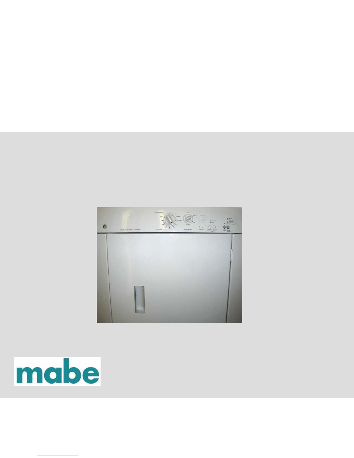
DRYER
PSXH47EFWW
07-MAN-DR-02
Page 2
2
TABLE OF CONTENTS
Important Safety Notice
3
Specification
4, 5
Component Resistances
6
FunctionTest Sequence
7, 8, 9
Electronic Control Board Circuits
10
Drive Motor Circuit
11, 12
Temperature Sensing Circuit
13
Heating Circuit
14
Drying Time
15
Troubleshooting
16, 17, 18
Error Code Chart
19, 20
Troubleshooting Flow Charts
21, 22, 23, 24
Wiring Diagram
25
mabe CONFIDENTIAL AND PROPRIETARY INFORMATION-NOT FOR PUBLIC DISCLOSURE. JANUARY 2007
Page 3
3
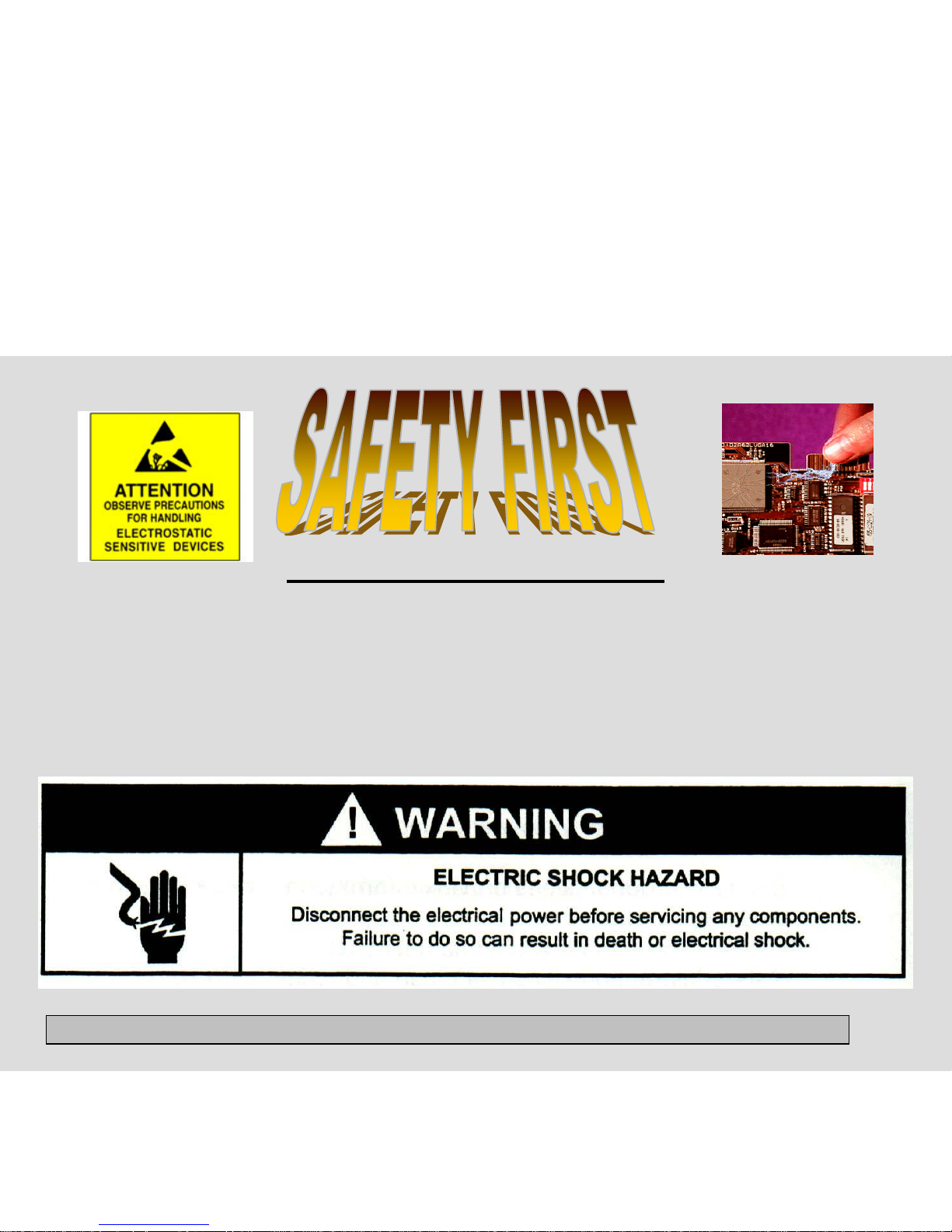
IMPORTANT SAFETY NOTICE
The information in this presentation is intended for use by individuals
possessing adequate backgrounds of electrical, electronic, and
mechanical experience. Any attempt to repair a major appliance may
result in personal injury and property damage. The manufacturer or
seller cannot be responsible for the interpretation of this information,
nor can it assume any liability in connection with its use.
mabe CONFIDENTIAL AND PROPRIETARY INFORMATION-NOT FOR PUBLIC DISCLOSURE. JANUARY 2007
Page 4
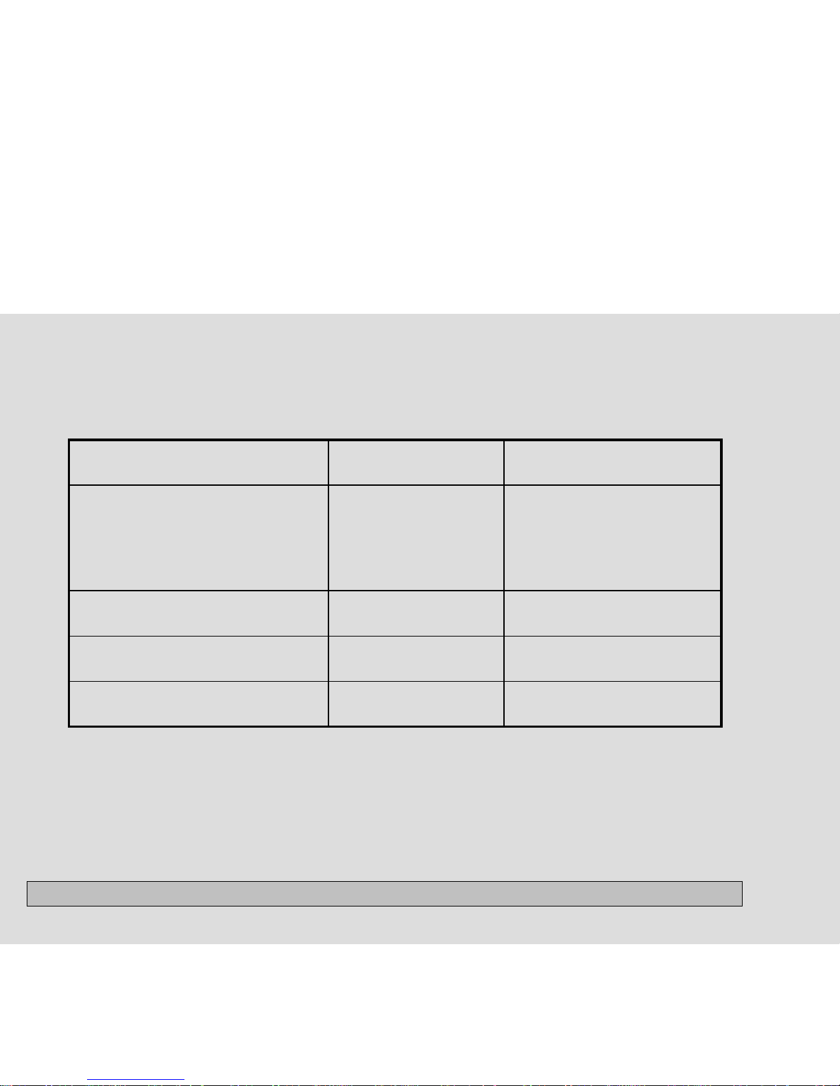
4
SPECIFICATIONS
SPECIFICATIONS ELECTRIC MODELS
GAS MODELS
Electrical
Volts 120/208 or 120/240
Amps (circuit)
Motor wattage
Heat input (watts @ 208/240 VAC)
Heat input (BTU/Hr.)
Auto. Elec. Ignition
120/208 or 120/240
30
160-350 watts
3200/4500
---
---
120
15
160-350 watts
--20,000
Yes
Drum
Size (Cu. Ft.)
R.P.M.
5.7
48 - 54
5.7
48 - 54
Airflow CFM
200 200
DRUM TEMPERATURES (Max.
opening on 1st cycle)
High
Medium
Medium/Low
Low
138° - 190°
134° - 180°
130° - 170°
120° - 165°
145° - 190°
140° - 180°
130° - 170°
120° - 165°
mabe CONFIDENTIAL AND PROPRIETARY INFORMATION-NOT FOR PUBLIC DISCLOSURE. January 2007
Page 5
5
SPECIFICATIONS (cont.)
SPECIFICATIONS ELECTRIC MODELS
GAS MODELS
Dimensions (Inches)
Height (Stack Models)
Width
Depth
36”
27”
28.5”
36”
27”
28.5”
Vent Capability** 4-Way 3-Way
Port Opening (Sq. In.) 235 235
** Electric dryers can be vented four ways: through back, bottom, right or left side.
** Gas dryers can be vented three ways: through back, bottom or right side.
mabe CONFIDENTIAL AND PROPRIETARY INFORMATION-NOT FOR PUBLIC DISCLOSURE. January 2007
Page 6
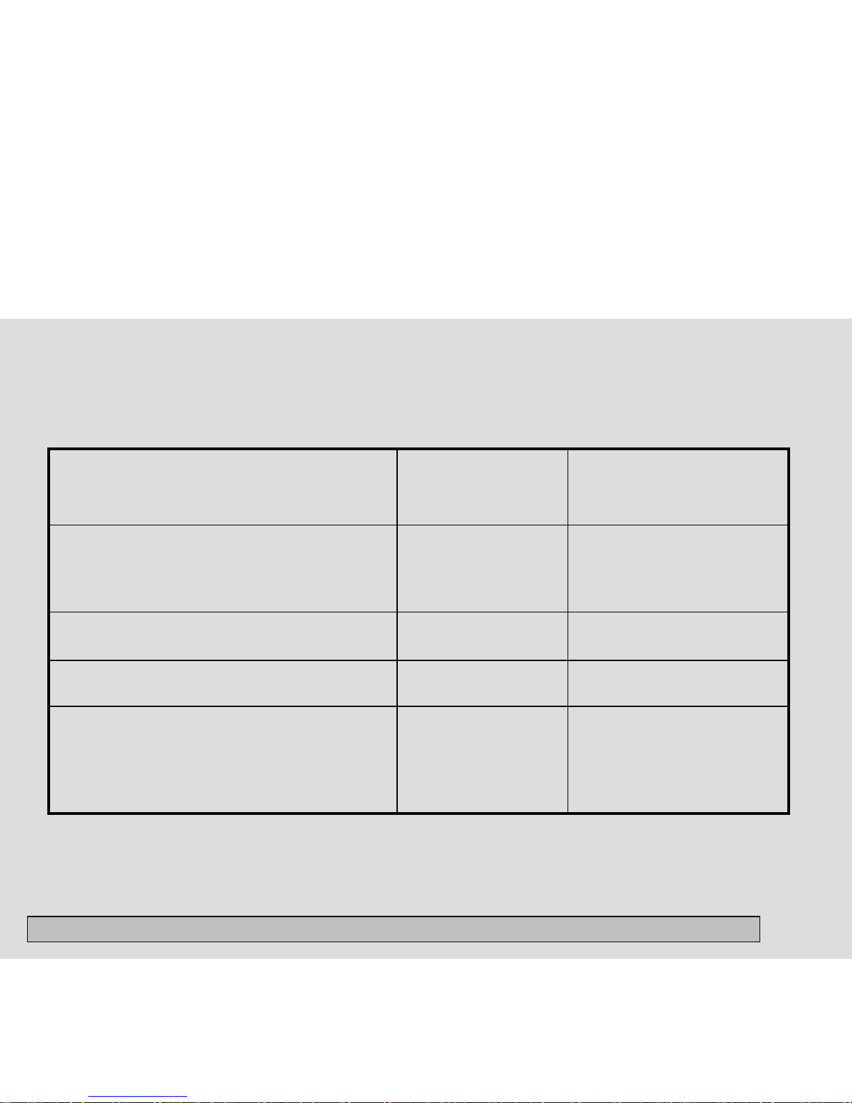
6
COMPONENT RESISTANCES*
Component Resistances* Electric Models Gas Models
Drive motor (120 volts, 60 Hz, 1/4 h.p. 1725 rpm)
Motor Start Winding
Motor Run Winding
4.5 Ohms
3.8 Ohms
4.5 Ohms
3.8 Ohms
Heating Element 12.8 Ohms
Control Thermistor 50,000 Ohms 50,000 Ohms
Burner Assembly
Ignitor
Secondary Coil
Booster Coil
---
---
---
50 - 400 Ohms
1200 Ohms
1320 Ohms
* +/-10% @ 77°F
mabe CONFIDENTIAL AND PROPRIETARY INFORMATION-NOT FOR PUBLIC DISCLOSURE. January 2007
Page 7

7
FUNCTION TEST SEQUENCE
This is a functional test for the dryer. To activate this mode, perform the following steps:
1. Turn the cycle selector knob to the 12 o’clock position.
2. Press and hold the SELECT and PAUSE CANCEL buttons simultaneously for 6 seconds.
3. Immediately after, press and hold the PAUSE CANCEL and START buttons for 4 seconds.
The control will enter the test mode, the buzzer will sound 3 times and all LEDs will rapidly
flash.
After entering the test mode, the selector can now be rotated to select the following tests:
1 Turn Drive motor runs; heat source is on. DRYING LED is lit. Control thermistor
reading is displayed. **
2 Turns Drive motor runs; heat source is off. COOL DOWN LED is lit.
3 Turns Drive motor runs; heat source is off. DRYING and COOL DOWN LEDs are lit.
The MORE DRY LED should be ON. Opening the door (press in on door switch plunger) and
placing a finger on both moisture sensor bars at the same time will make the DAMP LED
come on.
mabe CONFIDENTIAL AND PROPRIETARY INFORMATION-NOT FOR PUBLIC DISCLOSURE. January 2007
Page 8

8
FUNCTION TEST SEQUENCE (cont.)
4 Turns Drive motor runs; heat source is off.
a. When the TEMPERATURE selector is rotated, there should be a key beep with each setting.
b. When the DRYNESS key is pressed, all the dryness level LEDs should light.
c. When the OPTIONS or SELECT key is pressed, all the options LEDs should light.
d. When the START key is pressed, all the cycle status LEDs should light.
e. When the PAUSE CANCEL key is pressed, all the cycle status LEDs should light.
5 Turns Drive motor runs; heat source is off. COOL DOWN LED is lit. Control
thermistor reading is displayed. **
mabe CONFIDENTIAL AND PROPRIETARY INFORMATION-NOT FOR PUBLIC DISCLOSURE. January 2007
Page 9

9
FUNCTION TEST SEQUENCE (cont.)
6 Turns Drive motor runs; heat source is on.
DRYING LED is lit. Control thermistor reading is displayed. **
To exit test mode, press and hold the SELECT and PAUSE CANCEL buttons
simultaneously for six seconds or disconnect power from dryer. Dryer will be reset for
regular operation.
**The dryness LEDs are used to determine the control thermistor reading. The number of
flashes of the bottom three LEDs will determine the value of the temperature as follows:
NORMAL = HUNDRED’S
LESS DRY = TEN’S
DAMP = ONE’S
Example: NORMAL flashes 1 time.
LESS DRY flashes 2 times.
DAMP flashes 6 times.
Temperature = 126 degrees.
mabe CONFIDENTIAL AND PROPRIETARY INFORMATION-NOT FOR PUBLIC DISCLOSURE. January 2007
Page 10

10
ELECTRONIC CONTROL BOARD CIRCUITS
Line L1 is applied to the control board at pin 1 of the eight pin plug and neutral on pin 2 of the
eight pin plug.
The control board receives inputs from:
• the selector switch, the temperature switch and the push buttons which program the control;
• the contact sensors which sense the amount of moisture in the clothes;
• the control thermistor which senses the temperature in the dryer.
The control board uses these inputs to control the drive motor circuit by opening and closing
the contacts of relay RL1 and the heater circuit by opening and closing the contacts of relay
RL2.
mabe CONFIDENTIAL AND PROPRIETARY INFORMATION-NOT FOR PUBLIC DISCLOSURE. January 2007
Page 11

11
DRIVE MOTOR CIRCUIT
When power is connected to the dryer, line L1 is applied through the thermal limiter (a
non-resettable fuse mounted on the rear wall of the dryer ) to the COM terminal of the door
switch.
When the door is closed the COM terminal is connected to
terminal NO of the door switch. From terminal NO power is
applied to terminal J4-2 of the motor relay RL1 on the
control board. When the control board closes relay RL1
power is applied through terminal J4-1 to terminal M4 of
the drive motor.
Terminal M4 is connected inside the motor to one side of the thermal overload. (The thermal
overload protects the motor from being damaged by overheating.) The other side of the
thermal overload is connected to one end of both the run winding and the start winding of the
drive motor. When the motor is not turning, the other end of the start winding is connected
internally to terminal M5 of the motor through the NC contact of the motor centrifugal switch.
The other end of the run winding is also connected internally to terminal M5, which is
connected to neutral.
mabe CONFIDENTIAL AND PROPRIETARY INFORMATION-NOT FOR PUBLIC DISCLOSURE. January 2007
Page 12

12
DRIVE MOTOR CIRCUIT (cont.)
When the motor is not turning, the start winding and the run winding are connected in
parallel. When the contacts of relay RL1 are closed, with the dryer door closed, line L1
and neutral voltage is applied across both the start and run windings of the drive
motor. With power applied to both the start and run windings, the motor starts to turn.
When the speed of the motor reaches about 80% of it’s normal run speed, the contacts
of the centrifugal switch remove power from the start winding thus removing the start
winding from the circuit.
The drive motor performs two tasks in the dryer. A pulley attached to one end of the
motor shaft uses a belt to drive the dryer drum. The blower wheel is attached to the
other end of the motor shaft to pull the air through the clothes and force it out the
exhaust vent.
mabe CONFIDENTIAL AND PROPRIETARY INFORMATION-NOT FOR PUBLIC DISCLOSURE. January 2007
Page 13

13
TEMPERATURE SENSING CIRCUIT
The temperature in the dryer is
controlled by the control thermistor and
the electronic control board. The
control thermistor, mounted in the
blower fan housing, is a negative
coefficient thermistor that decreases in
resistance as the temperature
increases.
The electronic control board reads the resistance of the thermistor and
converts it to temperature. It compares the reading from the thermistor to the
temperature setting for the cycle.
mabe CONFIDENTIAL AND PROPRIETARY INFORMATION-NOT FOR PUBLIC DISCLOSURE. January 2007
Page 14

14
HEATING CIRCUIT
The electronic control board applies power to the heating circuit through the contacts
of heater relay RL2. When the electronic control senses the temperature in the drum
is below the programmed temperature, it closes the contact of RL2. This applies line
L1 power to the high limit thermostat mounted on the heating element assembly.
The high limit thermostat is a safety device that prevents
the dryer from overheating if the contacts of the RL2 fail
closed. The contacts of the high limit thermostat, normally
closed, are set to open at a temperature above the preset
temperature specifications of the electronic control board.
From the output terminal of the high limit thermostat, line
L1 is connected to one side of the element and to pin 3 of
the eight pin plug. The other side of the heating element is connected to line L2
through the contacts of the second centrifugal switch in the drive motor. This switch
prevents power from being applied to the element if the motor is not running.
The connection to pin 3 allows the control to monitor the contacts of the high limit
thermostat and show an error code if the contacts open above a preset number of
times in a cycle.
mabe CONFIDENTIAL AND PROPRIETARY INFORMATION-NOT FOR PUBLIC DISCLOSURE. January 2007
Page 15

15
DRYING TIME
The amount of drying time is determined in one of two ways. A fixed amount of drying
time is determined by turning the SELECTOR knob to one of the fixed drying times.
The AUTO DRY cycles a variable amount of time determined by the size of the load,
the amount of moisture in the clothes, and the dryness setting selected. In the AUTO
DRY cycle, the electronic control reads the capacitance between the two sensor bars
located in the vent cover.
When wet clothes are placed in the dryer, the clothes
touch the sensor bars and the moisture lowers the
capacitance between the bars. As the dryer runs, moisture
is removed from the clothes and the capacitance between
the bars increases.
When the increase in capacitance satisfies the electronic control, the cycle status
changes from AUTO DRY to COOL DOWN and the load is tumbled without heat.
At the end of cycle, the electronic control will turn the dryer off and the end-of-cycle
signal sounds.
mabe CONFIDENTIAL AND PROPRIETARY INFORMATION-NOT FOR PUBLIC DISCLOSURE. January 2007
Page 16

16
TROUBLESHOOTING
Service Error Codes
The electronic controls of the dryer have self diagnostics codes built in that cover
most product failures. When a failure occurs, the dryer stops or pauses.
The control will beep and flash the STATUS lights to tell the customer that a failure
has occurred. To stop the flashing and beeping, touch the PAUSE CANCEL button.
The error code remains stored in the control.
To view the error codes:
1. Rotate the cycle selector knob to the 3 o’clock position.
2. Press and hold the SELECT and PAUSE CANCEL buttons simultaneously for 6
seconds.
3. Immediately after, press and hold the START and Pause Cancel buttons
simultaneously for 4 seconds.
4. Rotate the cycle selector knob to the 2 o’clock position.
mabe CONFIDENTIAL AND PROPRIETARY INFORMATION-NOT FOR PUBLIC DISCLOSURE. January 2007
Page 17

17
TROUBLESHOOTING (cont.)
The four indicator lights of DRYING, COOL DOWN, EXTRA CARE and CLEAN LINT
FILTER will flash the number of times for the first digit of the code after the E, and the
START
indicator light will flash the number of times fo r the second digit after the E. The code is
obtained by counting the number of times the lights flash. Example E24: the four
indicator lights would flash twice indicating the 2 and the START indicator light will flash
four times indicating the 4. The four indicator lights and the START indicator light will
start flashing at the same time. The control will then pause for 2 seconds, then repeat
the code.
Troubleshoot the problem by using the chart on the next pages.
The error codes remain in memory until cleared from the control.
To move to the next code, press the OPTIONS button.
To clear the code, press the SELECT button.
To exit this mode, simultaneously press and hold the SELECT and PAUSE CANCEL
buttons for 6 seconds.
mabe CONFIDENTIAL AND PROPRIETARY INFORMATION-NOT FOR PUBLIC DISCLOSURE. January 2007
Page 18

18
TROUBLESHOOTING (cont.)
Note: A letter appearing in the code stands for a number higher than nine.
A = 10
B = 11
C = 12
D = 13
E = 14
F = 15
Example Code E4A: the first digit would be 4 and the second digit would be 10. If this
code would appear on a dryer, the four indicator lights would blink four times and the
START indicator light would blink ten times.
mabe CONFIDENTIAL AND PROPRIETARY INFORMATION-NOT FOR PUBLIC DISCLOSURE. January 2007
Page 19

19
ERROR CODE CHART
Error code Fault condition Action
E 10
E 11
E 12
E 24
E 25
Communication failure – EEPROM
Communication failure - Problem with
communication or memory did not check,
one has become corrupted
Communication failure - Memory
Shorted control thermistor
Open control thermistor
Clear code, exit mode and start dryer. If
the error persists, replace the control board.
Clear code, exit mode and start dryer. If
the error persists, replace the control board.
Clear code, exit mode and start dryer. If
the error persists, replace the control board.
Remove wires from the control thermistor.
Measure resistance of the thermistor. If the
reading is not 50K (+/-10%), replace
thermistor. If the reading is within 50K
(+/-10%) check wiring between thermistor
and electronic control. If good, replace
electronic control.
Remove wires from the control thermistor.
Measure resistance of the th ermistor. If
the reading is not 50K (+/-10%), replace
thermistor. If the reading is within 50K
(+/-10%) check wiring between thermistor
and electronic control. If good, replace
electronic control.
mabe CONFIDENTIAL AND PROPRIETARY INFORMATION-NOT FOR PUBLIC DISCLOSURE. January 2007
Page 20

20
ERROR CODE CHART (cont.)
Error code Fault condition Action
E4A
E 5B
E 68
E 8C
E AF
The drying time has exceeded program
time for that cycle.
No heat.
One of the keys (buttons)is stuck closed (active).
High limit t hermostat has tripped too many
times in a certain amount of time.
Microcontroller has been reset
by internal Watchdog timer.
Press PAUSE CANCEL and SELECT buttons for
6 seconds to exit test mode. Position cycle
selector to NORMAL, temperature selector to HIGH
HEAT, and touch START. Check for anything that
would extend dry times, such as no heat, restricted
vent, blower fan blade broken or loose, dryer installed
in closet with solid door, or bad connection in moisture
sensor bar circuit or dirty bars. If dryer operates
normally but code returns, replace electronic control.
Refer to flow chart “Drive motor runs but dryer does
not heat.”
Enter function test mode and perform key
(button) test to determine which button is at
fault. Carefully free the key and perform the test
again. If button is free but the key stuck code
still exists, replace electronic control.
Check for blocked lint filter, blocked
exhaust, air leaks around air duct, broken
blower fan blades, worn or loose drum seals,
dryer installed in closet with solid doors or
door seal not correctly seated.
Clear code, exit mode and start dryer. If
problem persists, replace electronic control.
mabe CONFIDENTIAL AND PROPRIETARY INFORMATION-NOT FOR PUBLIC DISCLOSURE. January 2007
Page 21

21
TROUBLESHOOTING FLOW CHARTS
Electric dryer completely inoperative. Note: Always check wiring to the components.
Note: If a fault code is displayed, the dryer will not operate.
Defective door
switch.
Defective thermal limiter.
NO
YES
YES
Refer to error
code chart.
Does the control beep or
the LED flash when the
START button is pushed?
Dryer completely
inoperative.
Measure the voltage drop
between the red wire on the
thermal limiter and neutral.
Measure the voltage drop
between pins 1 & 2 of J-4.
0
120VAC
0
0
Measure the voltage drop
between the orange wire
on the thermal limiter and
neutral.
NO
Is an error code displayed?
Defective household
power supply or
broken wire between
dryer terminal block
and thermal limiter.
120VAC
Defective
control board.
Measure the voltage drop
between pins 1 & 2 of the eight
pin plug of the wire harness to
the control board.
Defective control
board.
120VAC
0
Broken wire between
thermal limiter and the
control board.
120VAC
mabe CONFIDENTIAL AND PROPRIETARY INFORMATION-NOT FOR PUBLIC DISCLOSURE. January 2007
Page 22

22
Longer than normal drying times. (Possible E 4A)
Longer than normal
drying times.
Are the clothes wetter than normal
when removed from the washer?
Yes
Check washer
spin cycle.
No
Is the vent
restricted?
Yes
Clear vent.
No
Is the blower motor running
at full speed?
No
Replace motor.
Yes
Is the dryer level so the clothes
touch the sensor bars?
Is the dryer heating properly?
Yes
Level dryer.
No Yes
Review proper
programming of
the control with
the customer.
No
Refer to “Drive motor runs but dryer does not heat.”
flow chart.
mabe CONFIDENTIAL AND PROPRIETARY INFORMATION-NOT FOR PUBLIC DISCLOSURE. January 2007
Page 23

23
Clothes not dry in auto cycle.
Tested good.
Failed test.
No
Yes
Checks good. Checks bad.
Clothes not dry in the
auto cycle.
Using the function test, do the 3
o’clock test. (Refer to page 4.)
Check that the dryer is
level or slightly tipped
forward.
Are the sensor bars clean?
Clean bars.
Check the connections at the
bars and the wiring between the
control and the bars.
Replace the
electronic control.
Tighten the connections
or
replace the wire.
mabe CONFIDENTIAL AND PROPRIETARY INFORMATION-NOT FOR PUBLIC DISCLOSURE. January 2007
Page 24

24
Drive motor runs but dryer does not heat.
0
50,000 Ohms +/-10%
Drive motor runs but dryer not heat.
Check the resistance of the control thermistor at
room temperature.
Defective thermistor.
Program the dryer for a NORMAL Cycle with HIGH Temp and
touch START. Measure the voltage drop
between the two terminals of RL2.
Defective electronic
control board.
Measure the voltage drop between the two terminals of the
high limit thermostat.
Defective high
limit thermostat.
Remove power from the dryer and disconnect the black wire
from RL2. Restart the dryer and measure the voltage drop
between red wire on RL2 and neutral.
Open wire from
terminal block.
Remove power from the dryer, reconnect the black wire from RL2
and disconnect the plug from the drive motor. Restart the dryer and
measure the voltage drop between yellow and white wire in the plug.
Defective motor.
Defective
heating element.
More or less than
50,000 Ohms +/-10%.
240 VAC
0
240 VAC
0
120 VAC
120 VAC
0
mabe CONFIDENTIAL AND PROPRIETARY INFORMATION-NOT FOR PUBLIC DISCLOSURE. January 2007
Page 25

25
mabe CONFIDENTIAL AND PROPRIETARY INFORMATION-NOT FOR PUBLIC DISCLOSURE. January 2007
 Loading...