

Page 1
Training services to Mabe Consumer home
Service Manual
MODEL SERIES:
PSS and GSS
21, 23, 25, 27 and 29 cubic feet
PUB # 31-9072-SP 01/0
Page 2
IMPORTANT SECURITY NOTICE
The information in this service guide is intended to be used by
persons having adequate background with electrical, electronic and
mechanical experience. Any attempt to repair a large device can
result in personal injury and damage to the property. Manufacturer
or seller cannot be responsible for the interpretation of this
information, nor can take any duty in relationship with its use.
CARE
To prevent personal injury, disconnect power before servicing
this product. If electric power for purposes of diagnosis or test is
required, disconnect power immediately after making the
necessary check-ups.
RECONNECT ALL DEVICES TO LAND
If you wire them, screws, belts, fasteners, or nuts, the grounding,
used to complete a pass to earth are removed for service, should
be returned to his position original and adjusted properly.
Entrenamiento de Servicios a Domicilio del Consumidor de GE
Guía Técnica de Servicio
Copyright © 2001
Todos los derechos reservados. Esta guía de servicio no puede ser reproducida total o
parcialmente en ninguna forma, sin el permiso escrito de la General Electric Company.
!
Page 3

- 1 -
INDEX
Introduction
Installation
Specifications
Nomenclature
Operation characteristics
General views of localization
Mechanical disassembly
Diagnostics
Views of localization of components
and connector
Diagrams
Catalogs illustrated parts
. . . . . . . . . . . . . . . . . . . . . . .
2
. . . . . . . . . . . . . . . . . . . . . . .
3
. . . . . . . . . . . . . . . . . . . . . . .
4
. . . . . . . . . . . . . . . . . . . . . . .
5
. . . . . . . . . . . . . . . . . . . . . . .
6
. . . . . . . . . . . . . . . . . . . . . . .
13
. . . . . . . . . . . . . . . . . . . . . . .
15
. . . . . . . . . . . . . . . . . . . . . . .
29
. . . . . . . . . . . . . . . . . . . . . . .
52
. . . . . . . . . . . . . . . . . . . . . . .
59
. . . . . . . . . . . . . . . . . . . . . . .
60
Page 4
- 2 -
Introduction
2001 SxS Energy models are being introduced in response to
the requirements of more energy-efficient refrigerators by mid2001, along with improvements in features and operation. The
primary differences in this cooling system are the defrosting
adaptable system (watch Pub # 31-9062), control board,
software, and systems control that operate regardless in the
sections of the cooler and freezer. The new high-efficiency
control system has the ability of cycling components and
adjusting the fan speeds as required, to maintain the
temperature adjustment ranges in the cooler and freezer
sections. The feedback systems are digital inputs and relay
outputs. The sensors (thermistors) are used to measure the
temperature with communication to the main board, which
controls the components of the unity.
The refrigerator has key controls to give inputs to the
microprocessor. The cooler and freezer controls are of the
temperature control point type and have settings of 0-9 with 9
being the coldest possible temperature. The new NONCLEAN condenser is repairable from the back and is designed
to prevent the customer from having to
clean the condenser in conditional normal use.
The sealed operation system and the compressor are working
in the same way as the previous models, with some minor
changes.
The collateral models Profile Performance and Arctica are
the affected models. These models are available with cold
water through the door and ice dispenser, and a water filter
detail that can be filled. In models that require an ice
machine, the new electronic ice machine model (see Pub. #
31.09063) has been or can be installed.
The freezer has built-in grills, a spill-proof grill that pulls out,
an Easy Space grill, deep door grills, based on the model. The
chiller section has a Baking Soda holder, a fruit and vegetable
drawer, drawer dividers, and a moisture-adjustable drawer
and a convertible meat drawer.
The new high-efficiency refrigerator is a combination of the
most efficient refrigeration systems and the most desirable
customer details available.
Page 5
- 3 -
METODO
PREFERIDO
ASEGURESE QUE EXISTE
ADECUADA PUESTA A
TIERRA ANTES DE USAR
ETODO TEMPORAL
(En Canadá no se permiten
daptadores de enchufe)
ASEGURE ADECUADA
PUESTA A TIERRA Y
CONEXION FIRME
ANTES DE USAR
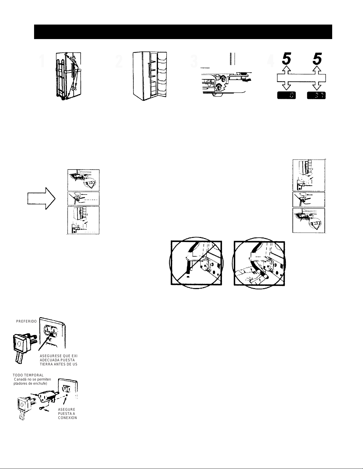
Installation
Tape
Use a cushioned hand truck to protect the
finished refrigerator. LEAVE
THE TAPE IN THE DOORS until it is in its
final location. LOAD ONLY FROM THE
SIDE. Avoid tighten the belt a lot to avoid
damage of the doors
REMOVE ALL THE PROTECTOR
TAPE FROM THE SURFACE, then
move the unit to its position. If the inlet
is less than 38" wide, remove the doors
before installation and reinstall them
according to the pro- bottom down.
Connect the water lines and the electric
cord. ADJUST THE FRONT ROLLS so
that the refrigerator is firm on the floor
and the doors close easily. MAKE SURE
THE DOORS ARE COUPLES ABOVE.
TEMPERATURE CONTROLS ARE
PRESCRIBED IN THE FACTORY
FOR RE-COMBUSED ADJUSTMENT
REMOVING THE DOORS
The doors must be in closed position.
Near the bottom hinge on the freezer side, tighten
the collar on the water line and pull the tubing from
the coupling. Also, disconnect the wiring from the
wire. Pull the water line and wiring through the
bottom rail.
Remove the covers of the upper hinges to access
the hinges. Remove the hinges using a Torx T-20.
Carefully turn the door by 90 °. Guiding the water
line and wiring the fence, lift the door straight up.
Avoid loading the lower hinges sideways. Place the
doors on a protected surface. Avoid piercing the
water pipe and wiring the wiring in the bottom of the
door.
With the doors open at 90 °, place them on the lower
hinge. Carefully turn the doors to the closed position.
Avoid loading the lower hinges sideways.
Reinstall the upper hinges and tighten the screws
firmly. Reinstall the hinge cover. If the doors are not
level, adjust the lower right hinges with a 7/16 open
end wrench.
Insert the water pipe back into the coupler. It is fully
connected when the mark on the pipe is no longer
visible. Reconnect the wiring of the wiring. Open the
water supply.
CABLEADO
ALAMB.
PUERTA
SUJET.
BISAGRA
CUBIERTA
BISAGRA
REBORD
CABL.
REBORDES
CUBIERTA
PUERTA
SUJT.
AJUSTE ALTURA
RODILLO
AJUSTE ALTURA PUERTA
CONTROLS ADJUSTMENTS
REINSTALLING THE DOORS
• HEET WAX IS RECOMMENDED TO REMOVE TAPE WASTE AND HAND FINGER FROM THE REFRIGERATOR OUTSIDE.
• REMOVE ALL TAPE AND PACKAGING MATERIAL FROM INSIDE REFRIGERATOR. DO NOT REMOVE THE SERIAL PLATE.
• REMOVE THE PROTECTIVE FILM ON THE TEMPERATURE CONTROL PANEL.
IMPORTANT: PLEASE READ CAREFULLY
FOR PERSONAL SAFETY, THIS APPLIANCE MUST BE ADEQUATELY GROUNDED
The power cord of this appliance is equipped with a three-prong (grounded) connector that fits a three-pronged (grounded)
standard receiver to minimize the risk of an electrical hazard to this appliance. The customer should check the wall receiver and
the circuit by a qualified electrician to make sure that the appliance is properly grounded.
Where a standard two-pronged wall receiver is located, it is the customer's responsibility and personal obligation to exchange it
for a properly grounded three-prong wall receptacle.
NDER NO CIRCUMSTANCES, CUT OR REMOVE THE THIRD POINT OF THE (EARTH) CONNECTOR FROM THE ENERGY
CORD. SITUATIONS OF USE IN WHICH THE ELECTRICAL CORD OF THE APPLIANCE WILL BE DISCONNECTED
INFRECTIVELY
Due to potential safety hazards under certain conditions, we strongly recommend against the use of an adapter plug. Without
em However, if you always choose to use an adapter where local codes permit, a TEMPORARY CONNECTION can be made to a
properly grounded two-prong wall receptacle approved by the UL adapter list which is available in most of the hardware stores.
The largest hole in the adapter must be aligned to give an appropriate polarity in the power cord connection.
to CAUTION: Connecting the terminal of the grounding adapter to the screw cover of the wall receiver does not ground
the device, unless the cover of the screw is made of metal, and is not insulated and the receiver of the wall is grounded through
the wiring of the house. The customer must check the circuit by a qualified electrician to make sure the receiver is properly
grounded. When disconnecting the power cord from the adapter, always hold the adapter with one hand. If you do not do this,
the terminal of the ground adapter is very safe to break with repeated use. If this happens, DO NOT use the appliance until a
ground connection has beenestablished
SITUATIONS OF USE IN WHICH THE ELECTRICAL CORD OF THE APPLIANCE WILL BE DISCONNECTED FREQUENTLY
Do not use an adapter plug in these situations because frequently disconnecting the power cord places undue stress on the
adapter and leads to eventual failure of the adapter terminal to ground. The customer must change the two-pronged receiver
on the wall for a receiver
Three-prong (grounded) by a qualified electrician before using the appliance.
Page 6
ELECTRIC SPECIFICATIONS
Temperature control………………………
Relay……………………………..…….....
Overload .................................................
Capacitor Func. (12 uF) .........................
Thermostat Overtemperature ................... Wiring
Wiring & Thermostat heat defrost .....
Heater Discong. & Clamp ..........
Fan Motor Condenser .....................
Fan Evaporator Engine ........................
Main Board ..................... ...................
Dispenser Board ..................................
Thermistor (EV) ............................................
Thermistor (FZ) ............................................
Thermistor (FF) ............................................
Thermistor (FF) ............................................
Fans Fan Motor ........................................
Shock absorber……………………………
wr55x10023
wr07x10031
wr08x10025
wr62x10079
wr50x10015
wr23x10142
wr51x10030
wr60x10042
wr60x10043
wr55x10024
wr55x10029
wr55x10025
wr55x10026
wr55x10027
wr55x10028
wr60x10051
Specifications
DISCONNECT THE POWER CORD BEFORE
SERVICING. -IMPORTANT- CONNECT ALL
EARTHED APPLIANCES AGAIN
All parts of this device capable of conducting electrical
current are grounded. If the wires, bolts, fasteners,
fasteners, nuts and ground washers used to complete a
grounding are removed for service, they must be returned
to their original position and be properly tightened.
IMPORTANT SAFETY NOTICE
This information is intended to be used by people
who have an adequate background in electrical,
electronic and mechanical experience. Any
attempt to repair an appliance can result in
personal injury or property damage. The
manufacturer or seller cannot be responsible for
the interpretation of this information, nor can it
assume any responsibility in relation to its use.
ELECTRIC SPECIFICATIONS
Temperature Control (Position 5) ................
Defrosting Control ........................... …….
Thermostat Overtemperature ...................
Defrosting Thermistor………....................
Electric Capacity: 115V, AC 60 Hz .........
Maximum Current Leak .................. ……
Maximum Resistance to Earth ................
Energy consumption……………………..
OPERATION WITHOUT LOAD
MID / MID Control Position
and Environment of:
Refrigerator, ° F .................................
Freezer, ° F ................................. ….
Func. Time,% ....................................
REFRIGERATION SYSTEM
Refrigerant charge (R134a) ..................
Compressor……………………………...
Minimum Compressor Capacity ............
Minimum Equalized Pressure
@ 70 ° F .................................... ………
@ 90 ° F .................................................
7-(-11)°F
60 hrs @ 35 min
without door openings
140-110°F
65°F
11.6 Amp
0.50 mA.
0.14 Ohms
KWH/month
70°F 90°F
34-40 34-40
(-3) 3 (-3) 3
<45% <70%
4.75 onzas
690 BTU/hr
22 pulgadas
48 PSIG
60 PSIG
Page 7
VOLUME
23/25/27/29
NOMENCLATURE
Profile Models 2001
P S S 2 5 I E M A F W W
Location of
the sheet
with
technical
information
(Remove the grid assembly
stuck under the cabinet)
- 5 -
INTERIOR/GRILL
D = Wire Deluxe I =
Vidrio Deluxe
J = Glass of first class
K = Glass against overflow
M = Glass against overflow/
Slides to the outside
Q = Derivative Exposure S =
Stainless Steel Doors U = ABV
Derivative V = Derivative
SEARS W = Derivative HPS
(Contract) X = Derivative
REGIONAL
PROF/ENERGY
S = ESTANDARD
T = TROPICAL
G = GLOBAL
BRAND/PRODUCT
G = GE
H = HOTPOINT
P = PROFILE (GE)
E = ETERNA (GE)
R = RCA
S = SELECT (GE)
ICE MACHINE / EXTERIOR
B = Not ready for dispenser / ice maker
D = Ice cubes / Water
E = Ice cubes and chopped / Water
F = Filter / ice cubes and chopped 6
months G = Filter / ice cubes and
chopped 1 year
i = Filter / Indicator & C / CW online
EXTERIOR COLOR
WW = White / White
AA = Almond / Almond
BB = Black / Black CC
= Bisque / Bisque WH
= White / Black BS =
Black / Stainless Steel
TYPE OF DOOR
F = Plane door (Line-
G) (ESPACIO = Door
Plane (S- & Línea-T)
K = Door of adjustment
YEAR MODEL
M = 2001
CONFIGURATION
S = Ref Door Col
DESIGN OF
NOMENCLATURE
A = INITIAL DESIGN
B = 1ST REVIEW.
Page 8

Operation characteristics
INDEX
Independent Operation of the Cooler / Freezer
............................................... 7
Normal Operation Characteristics, but Different
of Previous Models ........................................................................................................ 7
Features Abnormal Operation (Incorrect Operation) ..................................................... 7
Adaptive Defrosting ....................................................................................................... 7
Cooling Operation (Adaptive Defrosting) ....................................................................... 8
Pre-Cooling Operation (Adaptive Defrosting)
Operation Heater Defrosting (Adaptive Disconnect)
............................... 8
.............................. 8
Rest Period (Adaptive Defrosting) ................................................................................. 8
Post Rest (Adaptive Defrosting) .................................................................................... 8
Liner Protection Mode ................................................................................................... 8
Electronic Ice Machine .................................................................................................. 9
Dispenser functions ....................................................................................................... 9
Fast Ice ....................................................................................................................... 9
Door Alarm
Dispenser Light
............................................................................................... 9
.............................................................................................. 9
Closing the Dispenser .................................................................................................. 9
Filters ............................................................................................................................. 10
Hinge and Door Closing System ................................................................................... 10
Air Flow (Cabinet Interior) ............................................................................................. 10
Condenser "JELLY ROLL"
Main Control Board
.................................................................................. 11
.................................................................................. 12
Page 9

Independent Operation of the Refrigerator / Freezer
In previous models, the chiller and freezer compartment
components worked at the same time. When the cooler
compartment asked for cold air, the components of the
freezer compartment worked with the components of the
cooler compartment. This is called operation
no Independent.
In this model, the components of the compartment of
the cooler they can operate without the operation
of the components of the freezer compartment. This is called
independent operation.
Normal Operating Characteristics that may
Occur, but Different from Previous Models
• The ice machine's drill rotates in the direction of the
hands of the clock.
• The evaporator fan operates without the compressor or
condenser fan. Refrigerator fan is switched on.
• Post Rest (adaptive defrost), compressor fan and condenser
on with the evaporator fan off after the defrost cycle.
• Lining Protection Mode, fans come on when doors open
for 3 minutes.
• When the doors open, the fans turn off.
• There is no air flow to the cooler compartment when the
evaporator fan is on.
• The evaporator and compressor fan can operate
continuously for 8 hours.
• The fans change speeds, different levels of sound can be
noticed when this happens.
• Quick Ice Mode, the evaporator fan works for 48 hours
without stopping.
• Response time for drastic temperature changes is 2 to 10
minutes. The main control board will only respond to 8
degrees of temperature change per minute as determined by
the change of resistance of thesensor.
- 7 -
Abnormal Operation Characteristics (Incorrect
Operation)
• Cooler fan on and evaporator fan off.
• Evaporator fan on, cooler fan and compressor off,
and damper closed.
• Quick changes in fan speed, the fan takes at least 1
minute to change speeds.
• The compressor running without the condenser
fan. The compressor and condenser
fan forever must of functional to the same weather.
• The condenser fan running without the
compressor. The compressor and condenser fan
should always work at the same time.
Adaptive Defrosting
Adaptive defrosting can be described as a defrosting system
that adapts to the environment around the refrigerator and the
use of the home.
Unlike traditional defrosting systems that use
electromechanical timers with a
Fixed defrost cycle time, adaptive defrost uses intelligent
electronic control to determine when the defrosting cycle is
necessary. In order to achieve the correct defrosting time
cycle, the main control board monitors the following cooler
operations:
• Length of time when the refrigerator doors were
opened since the last defrost cycle.
• Length of time that the compressor has operated
since the last defrost cycle.
• Amount of time that the defrost heaters were on since
the last cycle of defrosting.
• Adaptive defrosting is divided into separate
cycles. These operations are:
• Cooling operation Pre-cooling
operation
• Defrosting Heater Operation Rest Period
• Post Break
See Pub # 31-9062 for more information on
Defrosting Adaptable
Page 10
Cooling Operation (Defrosting Adaptable)
During the cooling operation, the main control board
monitors door openings (cooler and freezer doors) and
operating time of the compressor. The length of time
between consecutive defrosts is reduced by each open
door. If the doors are not opened, the compressor will
work up to 60 hours between defrosting. If the doors open
frequently and / or for long periods, the operating time of
the compressor between defrosting will be reduced to as
little as 8 hours
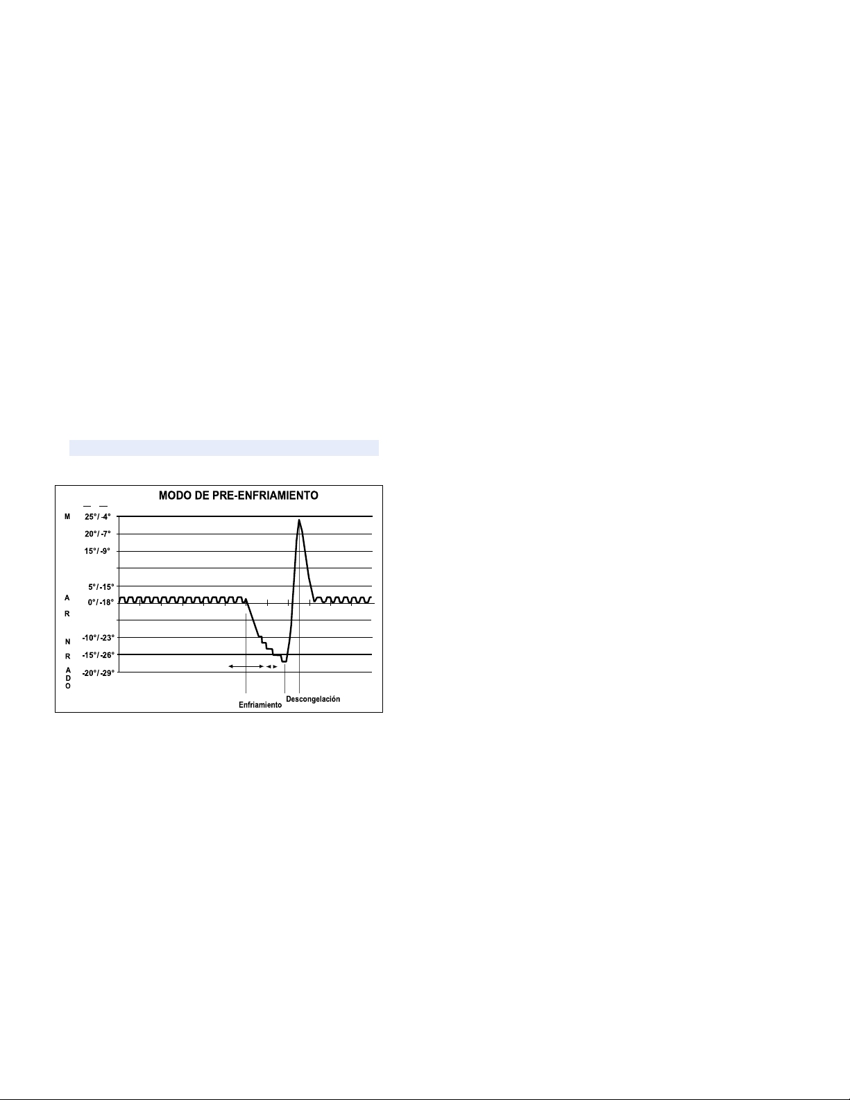
Pre-Cooling Operation (Defrosting
Adaptable)
When the main control board determines that the
defrosting is necessary, the main control board will force
the refrigerator to a continuous mode cooling (precooling). During pre-cooling, the freezer temperature can
be carried down the set point temperature of the control
panel screen. However, the temperature of the cooler will
be regulated by the shock absorber Pre-cooling and will
last 2 hours if it is not interrupted by some open door. If
after 8 hours, the unit could not complete a pre-cooling
without interrupting, the defrost cycle will continue.
Operation of the defrost heater
After 2 hours of pre-cooling operation or 8 hours of
interrupted pre-cooling attempts, the main control board turns
off the compressor, condenser fan and the evaporator
fan. The main control board then energizes the defrost relay,
which completes the Defrost Cycle.
A thermostat-defrosting (switch) protects the defrosting
system. The thermostat opens when the evaporator
temperature rises to 140 ° Fahrenheit and closes when the
evaporator temperature drops to 110 degrees Fahrenheit.
Rest Period (Adaptive Defrosting)
After the main control board has completed the operation of the
defrosting heater, there is a resting period of 5 minutes. During
this period, the compressor, condenser fan and evaporator fan
they stay off. Frost melting that remains of the evaporator will
continue to fall and drain to that the evaporator to be completely
clean of any humidity before the cooling operation. After 5
minutes of resting period, the unit enters a post break.
Post Rest (Adaptive Defrosting)
The post-rest period is designed to cool the evaporator before
circulating the air inside the refrigerator. This prevents any
residual heat in the evaporator from being distributed in the
freezer. During this period, the compressor and the condenser
fan are on, but all the interior fans are off and the shock
absorber is turned off. Post-rest times vary with the different
Models. However, there is a maximum of 5-minutes
of resting time.
Liner Protection Mode
The liner protection mode will be activated if any of the doors
have been opened for 3 minutes. This mode will start the fans
and will close the damper. This mode is controlled by 2
timers. Timer # 1 monitors door open time. A 3-minute open
count. The door will start when the door is opened. If it passes
3 minutes before the door is closed, the protection mode of
lining will be activated. Once the door is closed, timer # 1 is
reset and the liner protection mode passes to reserve. In
reserve, normal fan and damper operations begin and timer #
2 begins a count of 3 closed door minutes. If you spend 3
minutes without opening the door, the liner protection mode will
be completely deactivated. If a door is opened within the timer
#2 coun 2 closed door, the remaining time in door counting
closed the count of timer # 1 of open door will be deducted.
During the defrosting operation, the main control board monitors
the evaporator temperature using inputs to the evaporator
thermistor. The thermistor will usually end the operation of the
thermistor heater in less than 20 minutes. The typical thawing
time is 20-30 minutes.
- 8 -
Pre-
-5° / -21°
08:00 09:00 10:00 11:00 12:00 13:00 14:00 15:00 16:00 17:00 18:00
10° / -12°
F° / C°
T
E
P
E
R
A
T
U
R
A
S
I
E
E
F
I
R
Page 11

Electronic Ice Machine
This refrigerator is equipped with an Ice Machine
Electronics. For more information, see Pub # 31-
9063.
Dispenser functions
The main control board controls the functions of
water, crushed ice and cubed ice. To select a
function, press the appropriate key on the
dispenser. The led will light to identify the selection.
To dispense the chosen option, press the dispenser
holder located at the entrance of the dispenser. The
set of selenoid and link will open the ice firing gate
to dispense the ice. If cube ice is selected, the
solenoid deviation of crushed ice will allow cube ice
to be deviate from the ice crusher. The ice trigger
door must stay open for 5 seconds after it has
stopped the dispensation. After a delay of 5
seconds, the set of selenoid and link will close the
ice trigger door.
The dispenser light will turn on automatically when
the dispenser holder is depressed and will gradually
disappear 5 seconds after it was released. The
dispenser selection is recorded on the main control
board. In the case of a power failure, the last
selected function will be restored.
Fast Ice
The quick ice detail is available on some models.
This detail causes the evaporator fan to operate
without stopping for 48 hours (the fan can operate at
high or low speed). This allows a maximum output
of the ice machine.
The QUICK ICE key starts the quick ice mode in the
refrigerator. By pressing the QUICK ICE key the
LED is unlimited and adjusts the evaporator fan
operating at medium speed (unless the main control
board selects high speed) for a period of 48
hours. The evaporator fan is finished during
thawing, rest, post rest and doors opening.
The selection of quick ice is stored in the principal
control panel. The function will be restored in the
case of lack of energy.
Door alarm
The DOOR ALARM key is used to turn on and off the alarm
detail of the door. If the detail is on, the DOOR ALARM LED
will flash when the door is opened. If the door opens for
more than 2 minutes, the door alarm will sound. The alarm
can be stopped by pressing the DOOR ALARM key or
closing the door. If the DOOR ALARM key is pushed while
the door is open, the alarm will stop but the led will continue
to flash until the door is closed. When the door is closed, the
audible alarm will be restored. This detail will be retained in
the event of a power failure
.
Dispenser Light
The LIGHT key turns the dispenser light on and off. When the light
is off, it will gradually disappear. The dispenser light will turn on
automatically when the dispenser holder is depressed and will
disappear gradually 5 seconds after it was released. The LIGHT
key will not turn off the light while dispensing.
Closing the Dispenser
When the dispenser system is closed, no dispensing commands will
be accepted. This includes dispenser support and will prevent
accidental waivers that may be caused by children or pets. If you
press a key with the system closed, it will be recognized with three
presses of the LOCK LED accompanied by an audible tone.
To close or open communication between the dispenser and the
main control board, press the LOCK key and hold it for 3 seconds.
The LOCK LED will flash while the LOCK key is pressed. When the
communication is closed, the LOCK LED will light up.
The status of other functions, selected before the start of the closing
detail, will be displayed on the screen. If the latch is engaged while
a mode is activated, the LED will stay on until the mode ends.
If the latch is engaged when the filtering time ends, the LED will light
but cannot be reset until the latch is turned off.
The closing detail will be retained during a power cut.
Page 12
- 10 -
Filters
The FreshSaver filter is located in the fresh food drawer and
will last for 1 year. Some models are equipped with a
FreshSaver FILTER LED. After a 1-year refrigerator
operation time the FreshSaver filter LED will illuminate as a
reminder for the owner to change the filter. The LED can be
readjusted by pressing and holding the HOLD 3 SECS key for
3 seconds. The LED will flash while the key is pressed, it will
remain illuminated for 3 seconds after the key has been
released and turned off.
Some models are equipped with a water filter that is located
in the upper corner of the right side of the cooler
compartment. The filters are designed to be used for up to 18
hours of valve open time or 1 year of clock time.
When 90% of the filter time has passed (valve open time or
clock time, whichever comes first) the main control board will
illuminate the filter reminder LED (amber). When 100% of the
filter time has passed, the main control board will illuminate
the filter reminder LED (Red).
Hinge and Door Closing System
The hinge clamps are not adjustable in the cabinet. The
cooler door can be adjusted up and down using the hinge
adjustment pin (located on the bottom hinge of the cooler
door).
This refrigerator is equipped with an open / close door detail.
This detail consists of a loaded spring arm located in the
lower part of the cabinet for each door. The arm stops the
door when it is partially open and automatically closes the
door when it is almost closed
.
IMPORTANT:
The refrigerator rollers must be properly adjusted
for proper door closure. When the wheels are adjusted correctly,
the door should close easily when it opens approximately 45
degrees (half way).
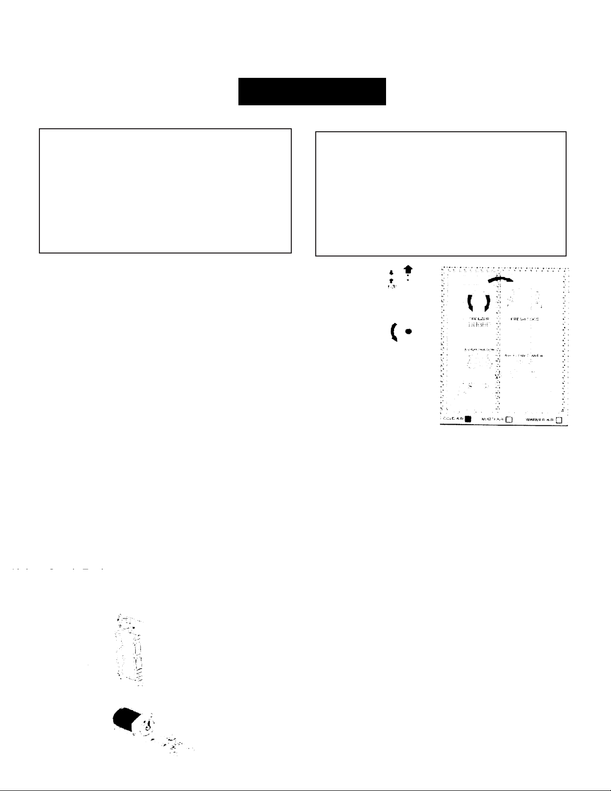
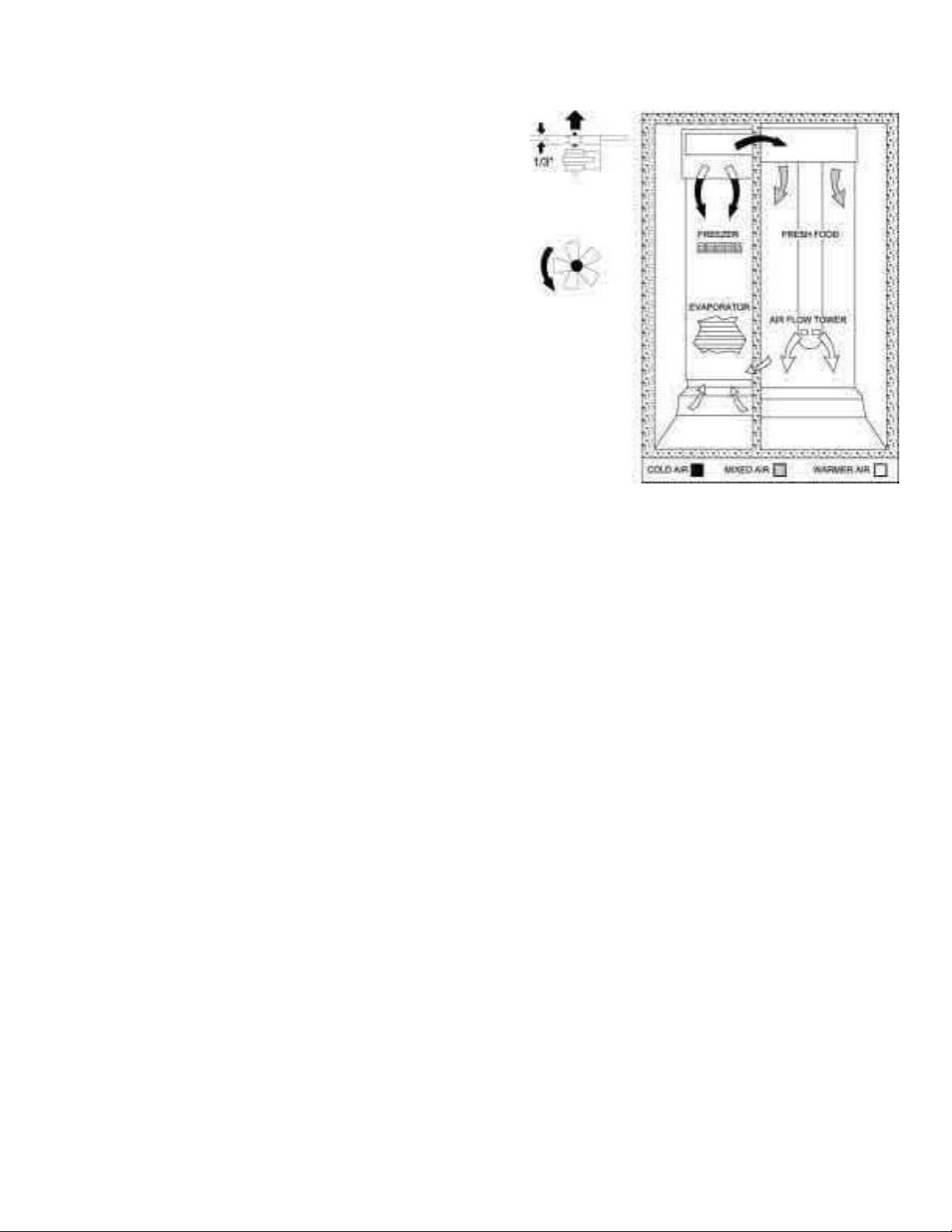
Air Flow (Cabinet Interior)
AIR FLOW
The freezer cabinet is designed so that air is carried inside the lower part
of the air tunnel and through the evaporator when the evaporator fan is
operating. The cold air is then pushed out towards the top of the freezer.
The cooler compartment receives cool air through an electronic shock
absorber that is located in the upper rear of the cooler between the freezer
cabinet and the cooler cabinet. The cushion is controlled by the main
control board and when it is opened, it allows the cold air from the freezer
air tunnel to move inside the cooler's air tower. The cold air tower of the
cooler contains a cooling fan that draws cold air from the freezer (through
the damper) into the air tower. The air tower directs cool air through the
top of the cooler cabinet to two exits. The air tower also directs cool air
down the back of the wall of the cooler cabinet. The cold air draws the air
out of the tower through fans in the tower.
The air returns from the cooler cabinet to the freezer cabinet through an
upright located on the left side of the fresh food drawer.
Page 13
- 11 -
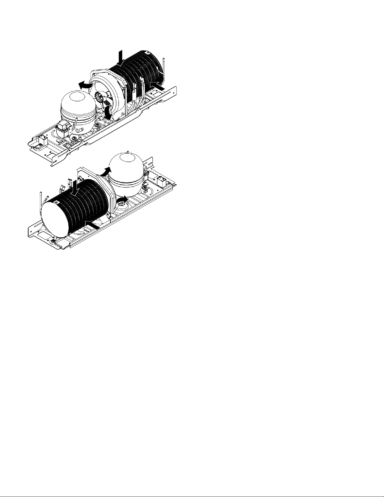
Condenser "Jelly Roll"
The "jelly roll" capacitor is a new type of capacitor. The
condenser fan is located at one end of the "jelly roll" condenser
and a solid plate is located at the other end. Air is drawn
through the outside diameter of the condenser and pulled out
by the condenser fan. The condenser is located in the
compartment of the machine that can be accessed through the
back of the unit in the background
.
GEA00911
Page 14
- 12 -
Main Control Board
ENTERS
IGNITION TIME OF THE DESCONG
HEATER. (MINUTES)
COMPRESSOR OPERATING
TIME (MINUTES)
OPEN DOORS ACCUMULATED
ENF AND CONG (MINUTES)
UNIT
PROCESSING
ENTRADAS
SWITCH
PUERTA
COMPRESOR
Y
DESCONGEL.
SALIDAS
SELECC.
MODELO
ENTRADAS
THERMISTO
R
ENTRADAS
CODIFICADOR
SERPENTINES
AMORT.
COMMUNICACION
ENTRADA/SALIDA
SALIDAS VENTILADOR
DEPARTURES
DEFROST.
PRE-COOLI
COOLING
1 COMM
2 +12V
3 -COM
4 DI
5 DO
L1
COMP
DESCONG
1
J4
LINEA
5 1
K4
COMP
J3
1
PAILA_CALT
N
K3
DESCONG. J6
10
DFZ
DFF
OCH
COMUN
AGUA
TRITR
TALADRO
2 1
J2
1
K5
QC
J7
8
K7
PAILA/CALT J1
1
K1
AUGER
K2
C/CR
K6
AGUA J5
9 6
Page 15
- 13 -
General views of the Locator
Temperature
Controls
Light
Freezer
Switch
Evaporator
Fan
Evaporator
Thermistor
Evaporator
Freez
er
Thermistor
Shock absorber
Coolant Thermistor
Switch Light Cooler
Page 16

- 14 -
GEA00977
Control
panel
Water
Solenoids
Fan
condenser
Jelly Roll
condenser
Overload and relay
(low cover)
Dryer
Page 17

- 15 -
Disarmed Mechanic
Content
Door Handle
Door packing
. . . . . . . . . . . . . . . . . . . . . . . . . . . . . . . . . . . . . . . . . . . . . . . .
17
. . . . . . . . . . . . . . . . . . . . . . . . . . . . . . . . . . . . . . . . . . . . . . . .
17
Quick Access to the Door of the Cooler Compartment . . . . . . . . . . . . . . . . . .
17
Switch Light Cooler Door. . . . . . . . . .
. . . . . . . . . . . . . . . . . . . . . . . . . .
18
Door Shelves of the Cooler Compartment . . . . . . . . . .
... . . . . . . . . . . . . . . . . . . . . . 18
Cooler Compartment Shelves ....................................................................................... 18
Cooler Compartment Drawers. . . . . . . . . .
. . . . . . . . . . . . . . . . . . . . . . . . . . . . . .18
Lights of the Cooler Compartment
. . . . . . . . . . . . . . . . . . . . . . . . . . . . . . . . . .
18
Water filter
. . . . . . . . . . . . . . . . . . . . . . . . . . . . . . . . . . . . . . . . . . . . . . . . . . . . . .
19
Fan Cushion and Chiller Study. . . . . . . . . . . . . . . . . .
. . . . . .
19
Shock absorber
DELIFRESH
. . . . . . . .. . . . . . . . . . . . . . . . . . . . . . . . . . . . . . .
20
Chiller Thermistors ......................................................................................................... 20
Temperature Control Panel. . . . .
. . . . . . . . . . . . . . . . . . . . . . . . . . . . . . . . . .
21
Freezer Door Drawers. . . . . . . . . . . .
. . . . . . . . . . . . . . . . . . . . . . .
21
Doors and Door Hinges
. . . . . . . . . . . . . . . . . . . . . . . . . . . . . . . . . . . . . . . . .
21
Adjustment of the Cooler
Door
. . . . . . . . . . . . . . . . . . . . . . . . . . . . . . . . . . . . . . . . . . . . .
22
Rollers
. . . . . . . . . . . . . . . . . . . . . . . . . . .. . . . . . . . . . . . . . . . . . . . . . . . . .
22
Roller Adjustment
. . . . . . . . . . . . . . . . . . . . . . . . . . . . . . . . . . . . . . . . . . . . . . . . . . . .
23
Freezer Compartment Shelves and Drawers .................................................................. 23
Switch Freezer Door Light .............................................................................................. 23
Ice Dispenser
. . . . . . . . . . . . . . . . . . . . . . . . . . . . . . . . . . . . . . . . . . . . . . . . .
23
Drill and Solenoid Drive of Ice Dispenser Cubes
. . . . . . . . .
24
Ice Machine ................................................................................................................... 24
Page 18

- 16 -
Freezer Light .............................................................................................................. 27
Evaporator Fan
Evaporator thermistor
. . . . . . . . . . . . . . . . . . . . . . . . . . . . . . . . . . . . . . . . . . .
27
. . . . . . . . . . . . . . . . . . . . . . . . . . . . . . . . . . . . . . . . . . .
28
Defrosting Thermostat
De-icer heater
. . . . . . . . . . . . . . . . . . . . . . . . . . . . . . . . . . . . . . .
28
. . . . . . . . . . . . . . . . . . . . . . . . . . . . . . . . . . . . . . .
28
Paila Evaporator Collector ......................................................................................... 29
Evaporator ................................................................................................................. 29
Freezer Thermistor .................................................................................................... 29
Condenser Fan .......................................................................................................... 30
Main Processor Card ................................................................................................. 30
Water solenoids ......................................................................................................... 30
Page 19
- 17 -
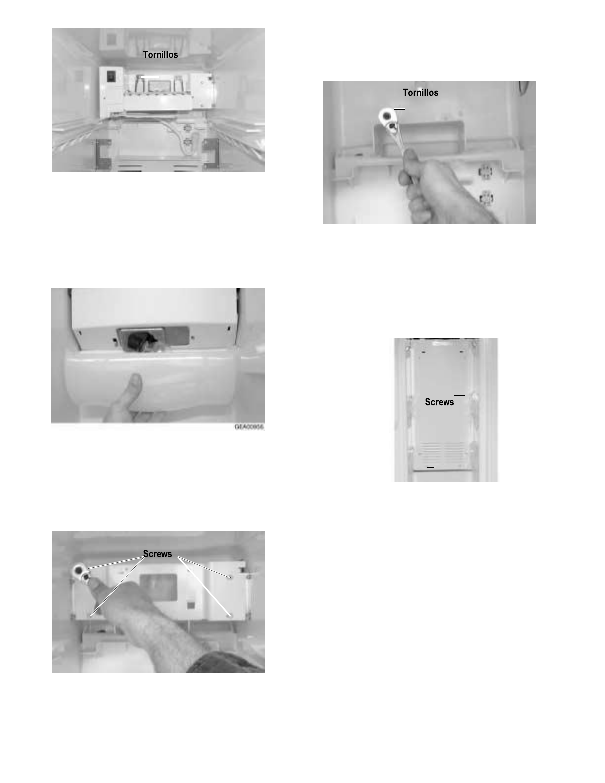
Door Handle
The door handles allow access to the cooler and freezer
compartments. They are mounted in front with 1 Torx head
screw.
1. Using a small flat-bladed screwdriver, slide the trim of the
handle down and pull it out.
2. Remove the lower Torx head screw.
3. Lift the handle with a movement of the inside and up until
the locking ears disengage. Pull the handle out to remove it.
Door packing
The door gasket is a packing set molded
inside a channel located in the door shell.
Door of Easy Access to the Comparison
of the Cooler
The cooler compartment allows access without
opening the cooler door.
1. Open the easily accessible door and remove the Torx head
screws on the hinge (2), located on each side of the door.
2. With a small flat-blade screwdriver, remove the door
frame and door frame assembly.
3. Remove the packing and slide the door out of the frame.
4. The easily accessible door also has an interlock switch
located on the upper right side of the interior frame. Remove
the Phillips screw and slide the switch assembly down and
out.
5. Disconnect the switch wires and remove them.
1.
Open the door.
2. Grasp the gasket and pull it outward until the molded
gasket separates from the door shell
Page 20
- 18 -
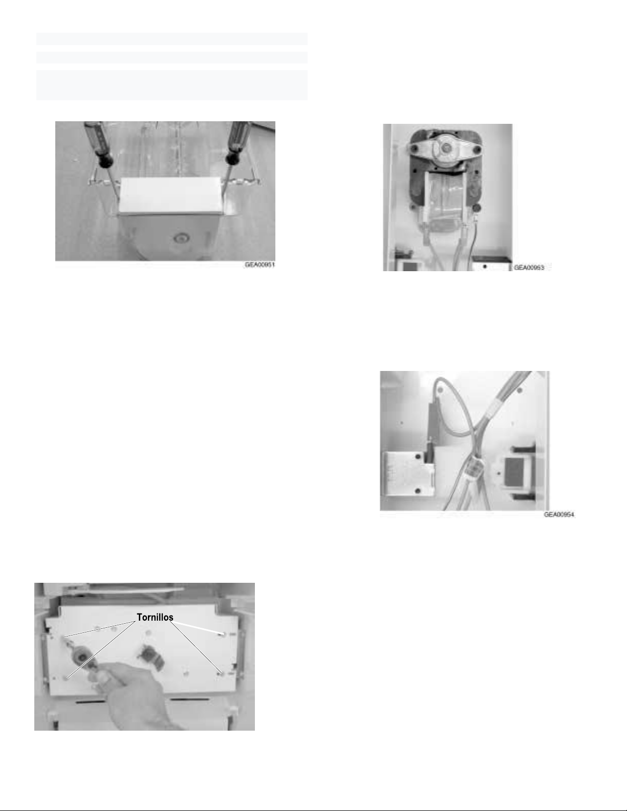
Switch of the Cooler Door Light
In addition to the easy access door light switch, cooler
compartment has a door light switch located on the
corner-right next to the compartment.
1.Use a small flat blade screwdriver to open the
locking lugs and pull the switch out until the
connector wire is visible.
2. Disconnect the connector and remove the
switch.
Door Shelves of the Cooler Compartment
The door shelves allow you to store perishable items
GEA00928
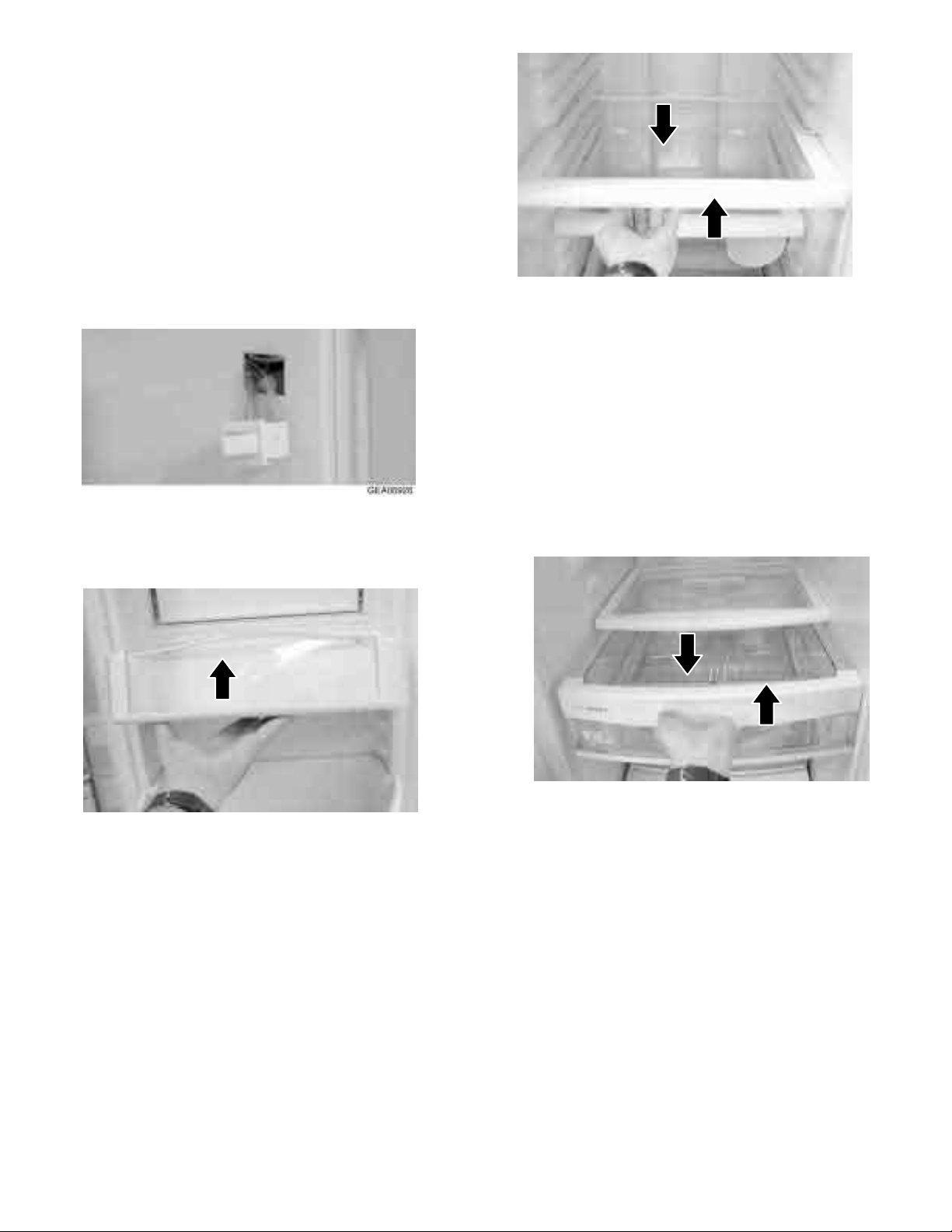
Cooler Compartment Drawers
The cooler compartment drawers are designed
to store fruits, vegetables and DELI items. The
drawers are located in the lower part of the
cooler compartment.
1. Pull the drawer out until the Rhodes are the
mechanical stop.
2. Tilt the drawer upwards and pull out until it is
withdrawn.
1.
Tilt the shelf up and slide it out.
GEA00929
GEA00927
Cooler Compartment Shelves
These shelves allow storage of larger items and
pull them for easy access.
1.
Pull the shelf until the stop tab on the shelf
meets the compartment stop.
2.
Push the stop tab of the shelf down and
pull the shelf out until it is removed.
Lights of the Cooler Compartment
The chiller compartment lights are located on
top and bottom of the chiller compartment.
1.
To access the top lights, remove the opaque
cover by opening the lugs and pulling the cover
down.
Page 21

- 19 -
GEA00930
2. To access the lower lights, pull out the DELI FRESH
shock absorber knob.
3. Lift the opaque cover of the lugs.
GEA00931
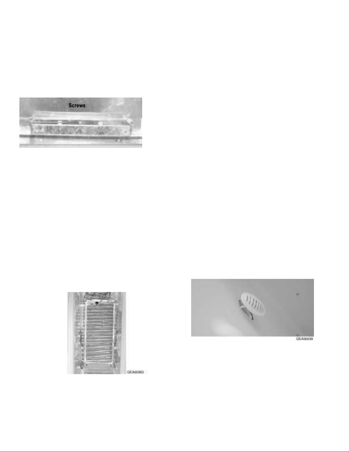
Cooler fan and shock absorber
The cooler compartment fan is located below the top
working duct in the cooler compartment. This fan
distributes the cold air of the freezer through the
cushion mount. The shock absorber post is located
in the same assembly as the fan. Both are controlled
by the processor.
1. Remove the DELI FRESH adjustment knob and
the light cover.
2. Open the top and bottom parts by locking lugs for
the center work duct and remove it. The work duct is
also fastened with a double-sided adhesive tape on
the upper and lower parts
Water filter
The water filter is located on the upper right side of the
cooler compartment. The water filter filters the water
for the ice machine and the water dispenser. An LED
on the temperature control panel will light up when the
filter needs to be changed.
1. Turn the water filter 1/2 turn counterclockwise and pull it
down.
2. To install the filter, push it in while turning 1/2 turn
clockwise. Do not force the filter.
Page 22

- 20 -
1. Remove the upper cover of the water filter.
2. Open the lugs of the opaque top light cover and
remove the cover.
3. Open the upper lugs of the work duct and remove
it
GEA00934
4. Remove the screws (8) Phillips head for the
plastic clamp assembly of the upper light.
9. Place the fan and shock absorber assembly
against the compartment and open the rear cover.
10. Disconnect the wire connections and remove the
damper or fan.
Shock absorber DELI FRESH
The DELI FRESH damper is located below the cold air duct.
Allows the cold air flow to be adjusted to the DELI FRESH
drawer.
1. Remove the DELI FRESH damper by adjusting
the knob and lower light cover.
2. Remove the center duct by opening the top and
bottom lugs. Double-side adhesive tape is
applied to the upper and lower areas.
3. Remove the screws (3) Phillips head mount the
shock absorber and remove the shock
absorber.
GEA00935
7. Pull down the stainless steel light clamp until the wires are
exposed and disconnected.
8. Remove the screws (2) Phillips head from the cooler fan
and from the shock absorber cover and remove the cover.
ChillerThermistors
GEA00938
The cooler thermistors are located in the upper
and lower parts of the cooler compartment. They send
temperature signals to the processor.
GEA00936
Page 23

- 21 -
1. Using a small flat-bladed screwdriver, open the
lugs and remove the assembly.
2. Remove the thermistor from the cover and
disconnect the wire connector..
Freezer Door Drawers
The freezer door drawers are located on the inside of
the freezer door and are tilted outward to allow easy
access to frozen items.
1.
Tilt the drawer and slide out the door.
Panel de Control de Temperatura
The temperature control panel is located in the cooler
compartment and mounted on the upper front part. This
panel allows temperature control for the cooler and
freezer compartments. Each compartment has a reading
LED of the temperature setting
Puertas y Bisagras de la Puerta
GEA009
In addition, the panel has a reading LED for the change of
the water filter.
1. Remove the Phillips head mounting screws (3) from
the control panel.
2. Pull the panel down until the connections are
exposed.
IMPORTANT: The freezer door is not adjustable. The
cooler door can be adjusted up and down to match
the height of the freezer door. Adjust the cooler door
up or down using the adjustment hinge (located on
the lower hinge of the cooler door).
IMPORTANT: The rollers of the refrigerator must be
adjusted correctly to ensure an adequate closing of the
door. For more information see the Roller Adjustment
section in this chapter.
4. Disconnect the wire connector from the panel.
5. Disconnect the ribbon from the circuit board.
GEA00940
1.
Remove the grid from the base.
2.
With the door in the closed position, disconnect the
wire wiring connector.
3.
Disconnect the water tubing
6. Open the closing lugs of the cards located on the left
and right bottom corners of the card.
7. Remove the card.
To disconnect the tubing, push the white flange on
the quick connector inward and pull the tubing out.
GEA00943
Tornillos
Page 24

- 22 -
4. With a small flat-blade screwdriver, unhook the locking
lugs from the cover of the upper hinge and remove it.
5. Remove the screws (2) Torx head from the hinge and
lift the upper hinge of the unit
CAUTION: Do not load the hinges aside.
CAUTION: Only the freezer door - Do not allow the connector
to make contact with the floor. A hard contact can damage the
connector.
NOTE: Guide the water line and wire harness through the
hinge while lifting the hinge door.
1. Open the door 90 ° and lift it straight up and out of
the lower hinge
Manguito
Pasador Bisagra
Tornillo Torx
GEA00908
4.
Remove the screws (3) Torx and the
lower hinge of the cabinet
Manguito
Bisagra
Ajuste Pasador
Bisagra
Tornillo Torx
Lower Hinge, Side of the Cooler
Cooler door adjustment
IMPORTANT:
The freezer door is not adjustable. The
cooler door can be adjusted to match the height of the
freezer door.
IMPORTANT:
The refrigerator rollers must be correctly
adjusted to ensure an adequate closing of the door. For
more information see the Roller Adjustment section in
this chapter.
1. Remove the grid from the base.
2. Turn the hinge adjustment pin (located on the bottom
hinge of the cooler) clockwise to raise the door level and
counter- clockwise to lower the door.
Rollers
The unit has 4 rollers for easy movement of the
refrigerator. There are 2 rollers located on the front and
2 rollers located on the back of the unit.
IMPORTANT: The rollers of the refrigerator must be
adjusted correctly to ensure an adequate closing of the
door. See Roller Adjustment.
1. To remove the front rollers, reverse the level
adjustment screw completely.
2. Remove the 1/4 "roller mounting bolts and remove the
mold.
GEA00945
3. To remove the rear screws, remove the 1/4 "mounting
screws (2).
4. Tilt the roller down and slide it out.
Tornillos
Page 25

- 23 -
Adjustment of the roller
The front rollers (2) are adjustable. Adjust them so
that the refrigerator is solid and the doors close
easily:
1. Remove the grid from the base.
2. Using a flat-blade screwdriver, turn the adjusting
screw clockwise to raise the roller and counterclockwise to lower the roller.
Freezer Compartment Shelves and Drawers
Shelves and drawers slide out for easy access to
frozen items.
Ice dispenser
Ice dispenser
The ice dispenser is located in the upper part of the
freezer compartment. The set stores the ice made by
the ice machine and removes it as required by the
surface switch of the door dispenser.
1. Remove the upper tray from the ice tray.
2. Slide out the ice dispenser assembly.
.
1.
Slide the shelf / drawer out until it reaches a stop
2.
Tilt the shelf / drawer up and slide it out of the
compartment.
GEA009
47
Light Switch Freezer Door
The switch is located on the right side of
the freezer compartment and sends
signals to the processor.
3. Remove the ice cube selenoid Phillips head
screw union and slide the union backwards.
4.
Remove the Phillips head screws (2) from the
ice crusher cover and remove it.
5.
With a pair of pliers, bend the tabs
of the backing plate on each side of the disposer.
1. With a small flat blade screwdriver, open the
locking tabs and pull the switch until the connector
wire is visible.
2. Disconnect the wire connector and remove the
switch.
Page 26
- 24 -
6.
Using two small flat blade screwdrivers, open the ice
crusher locking lugs located on each side of the ice
crusher.
7.
Lift the ice crusher out of the bucket
.
8.
Remove the back cover of the ice crusher.
9.
Remove the closing ring from the disposer drill of
ice.
10.
Remove the plastic nut with a pair of pliers by
turning it clockwise.
11.
Remove the spacers and blades. The blades are
listed for reassembly.
Cube Slew and Ice Dispenser Drill Driver
The drive motor of the ice dispenser and the cube
solenoid are located in the upper rear part of the
freezer compartment. The drive motor moves the drill
by means of a fork located in the drive motor. The cube
solenoid allows the cube or crushed cube to exit when
requested.
1. Remove the screws (4) 1/4 "mounting from the box
located in the four corners of the box.
2. Slide the box forward until the connector is visible,
disconnect the connector, and remove the unit from
the box.
Note: The drive fork has inverse threads, turn them
counterclockwise to remove them.
3. Remove the fork of the drive motor by turning
it clockwise.
4. Disconnect the motor connectors and remove
the ground wire.
5.
Remove the 1/4 "mounting screws (3) and remove
the motor.
6. Disconnect the wires from the cube solenoid.
7. Remove the mounting screws (2) from the 1/4
"socket solenoid and remove the cube solenoid.
Ice machine
The ice machine is located in the upper back part of
the freezer compartment and supplies ice to the
dispenser bowl.
1. Disconnect the cable connector from the
icemaker.
2. Remove the 1/4 "mounting screws from the ice
machine and slide the ice machine out.
This refrigerator is equipped with an Electronic Ice
Machine. For more information see Pub # 31-9063..
GEA00952
Page 27
2
.
Remove the ¼” screws (2) de 1/4" from the mounting
clamp of the ice dispenser and remove the clamps
Freezer Light
GEA00955
The freezer light is located on the back of the freezer
compartment. The light is covered with an opaque cover.
1. Open the locking lugs and remove the cover.
2. Change the light of the appliance.
GEA00958
3.
Remove the 1/4 "screws (2) from the upper duct of the
evaporator fan.
4. Open the lugs and remove the lower duct from the evaporator
fan.
5. Remove the 1/4 "screws (4) from the evaporator cover and
remove the cover.
Evaporator fan
The evaporator fan is located in the upper rear part of the freezer
compartment. This fan supplies cold air to the freezer and cooler
compartments. The evaporator thermistor must be replaced when
changing the fan.
1. Remove the 1/4 "mounting screws (4) from the ice machine
clamp on the four corners of the clamp.
GEA00959
6
. Remove the two 1/4 "upper duct screws from the evaporator
fan located on the bottom of the duct.
7. Using a small flat-bladed screwdriver, open the lugs for the
ice machine and dispenser cables.
8. Slide out the upper fan duct.
9. Disconnect the wiring from the evaporator fan wiring.
GEA00957
- 25 -
Page 28

- 26 -
Thermostat Defrosting
The defrost thermostat is pressed to the top of the
evaporator. The thermostat sends temperature
information to the processor. The defrosting heater must
be replaced when you change the thermostat.
1. Remove the lower fan duct from the evaporator cover.
2. Remove the 1/4 "screws from the evaporator cover
and remove the evaporator cover.
3. Remove the thermostat defrosting
.
Evaporator Thermistor
The evaporator thermistor is pressed in the upper part
of the evaporator. The thermistor sends temperature
signals from the evaporator to the processor. The
thermistor must be replaced when changing the
evaporator fan.
1. Complete the evaporator fan procedure.
2. Release the evaporator thermistor and remove it.
GEA00961
GEA00963
Thermist
Tornillos
7. Remove the 1/4 "screw of ground wire from the
evaporator fan.
8. Remove the 1/4 "screws (2) from the
evaporator fan mounting bracket located on each
side of the clamp
9. Remove it
Defrosting Heater
The defrosting heater is located in the lower part of
the evaporator. The defrost heater heats the
evaporator in the defrost operation mode. The
thermostat must be replaced when changing the
defrost heater.
1. Complete the defrosting thermostat procedure.
2. Remove the screws (2) Phillips head mounting
defrosting heater.
3. Remove the defrosting heater.
Page 29
- 27 -
Evaporator Collector Shovel
The collecting pan of the evaporator is located
below the evaporator. This blade collects the
condensation of the evaporator that is
generated during the defrosting operation
mode.
1. Remove screws (2) of 1/4 "mounting
bracket.
2. Remove the pick-up pan.
Evaporator
G
E
A
0
0
9
6
4
.
Air is conducted through the evaporator coils to produce
cool air for the freezer and cooler compartments.
1.
Remove the lower duct from the evaporator fan.
2.
Remove the 1/4 "screws (4) from the evaporator cover
and remove the evaporator cover.
3.
Remove the defrosting thermostat and the evaporator
thermistor.
4.
Remove the screws (2) Phillips head of the defrosting
heater and remove the heater.
5.
Remove the 1/4 "mounting screws (4) from the
evaporator located in the four corners of the
evaporator.
Freezer Thermistor
The freezer thermistor is located in the center of the right wall of
the freezer compartment. It sends temperature signals to the
processor.
1. Using a small flat-blade screwdriver, open the lugs
and remove the assembly
2. Remove the thermistor from the cover and
disconnect the wire connector.
Warning: To avoid damage to the capillary
tube, the capillary tube must be remove weld
first.
6. Unsolder the capillary tube of the evaporator.
7. Remove weld of the suction line. Use a pair
of tongs to hold the evaporator.
8. Remove the evaporator.
9. With a file, tear the capillary tube just below
the ex welded section. Break the dis-welded
section of the capillary tube. This helps prevent
the soldering iron from plugging into the tube
during assembly.
10. Place the new evaporator inside the freezer
and insert the suction and capillary tube inside
the evaporator.
11. Solder the suction and capillary tube to the
evaporator using a silver soldering iron.
12. Install a replacement for the evaporator
13. Recharge the system using the actual
acceptable procedures
Page 30

- 28 -
Condenser fan
The condenser fan is located on the back of the unit.
Gives FORCED-DRAFT cooling for the condenser
coil.
1. Remove the 1/4 "screws (5) from the rear access
panel and remove the rear panel.
Water selenoids
GEA0096
When the selenoids receive a signal from the
processor, they send water to the filter, cooler and ice
machine.
1. Remove the 1/4 "screws (10) from the rear panel
and remove it.
2. Remove the 1/4 "screw from the clamp.
3. Slide the solenoid assembly outward.
4. Disconnect the cable assembly.
5. Disconnect the water pipe. To disconnect the quick
connection, push the black lip in and pull the tube out.
6. Remove the solenoid
2. Remove the 1/4 "mounting screw from the
condenser fan and slide the fan until the wire is
exposed.
3. Disconnect the supply wire connector.
Main Processor Card
The main processor card is located on the back of
the unit. This card controls the operation of the unit.
If a cut on a fan has occurred, replace the fan
before the card and the card will be destroyed.
1. Secure the power to the unit.
2. Remove the 1/4 "screws (10) from the
processing board panel and remove the panel.
3. Disconnect the processor connector cables.
4. Remove the card by opening the plastic lugs
located at the corners of the card.
Page 31

Diagnostic
Content
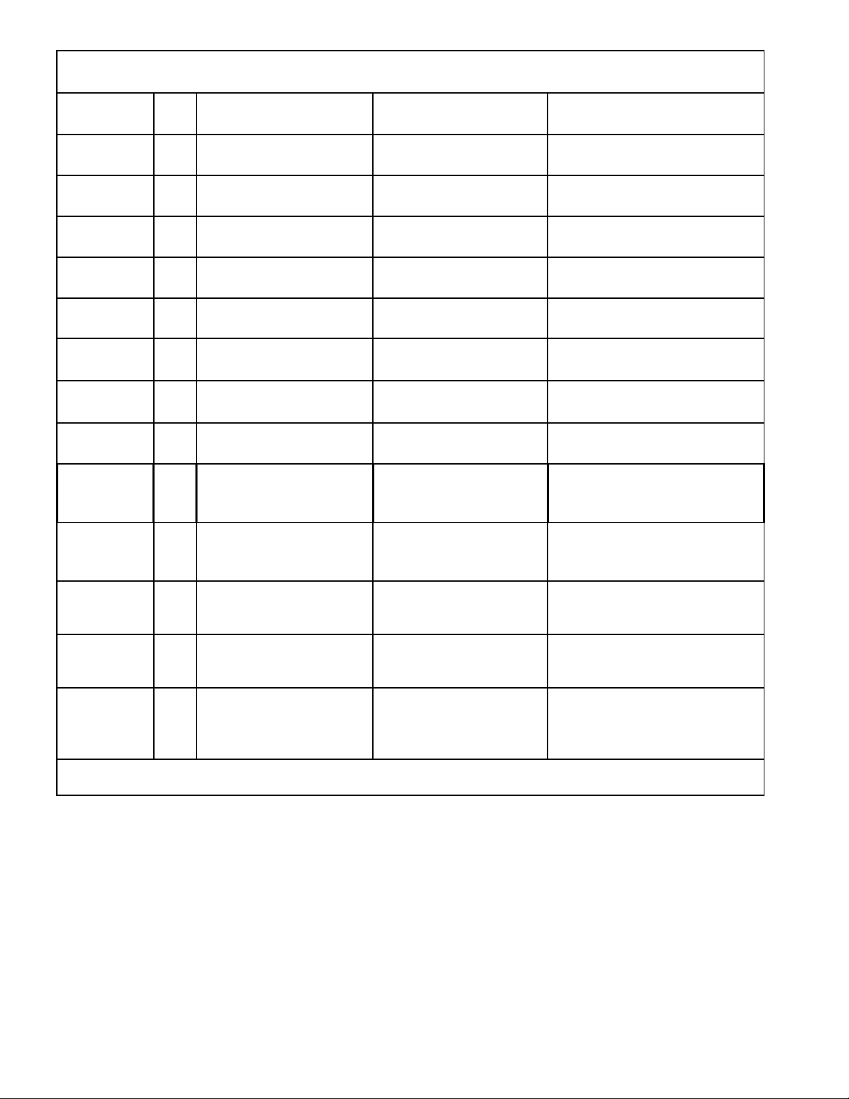
Efficient use of the Diagnostic……………………………………………………………………………………….29
Causes of failure (Table 1). . . . . . . . . . . . . . . . . . . . . . . . . . . . . . . . . . . . . . . . . . . . . . . . . . . . . . . . . . . . . . . . . . . 30
Automatic diagnostics……………………………………………………………………………………………………… 30
Diagnostic Tests (Table 2). . . . . . . . . . . . . . . . . . . . . . . . . . . . . . . . . . . . . . . . . . . . . . . . . . . . . . . . …………. . . . 32
Communication Tests (0 2, 03 or 0 4) ……………………………………………………………………………………32
Self-Test Temperature Control Panel (0 6). . . . . . . . . . . . . . . . . . . . . . . . . . . . . . . . . . . . ………………… . . . . . 32
Dispenser Board ……………………………………………………………………………………………………………33
Self-Test of the Control and Sensor System (0 7)………………………………………………………………………. 33
Main Control Board (Low Voltage Side)…………………………………………………………………………………… 34
Main Control Board (Side 120-VAC). . . . . . . . . . . . . . . . . . . . . . . . . . . . . . . . . ………….. . . . . . . . . . . . . . . . . . . . 35
Table Locator Board of C.o.n.tr.o.l.P.r.in.c.ip. to. l (.L.a.d.o. D. E.B.a.jo.V.o.l.ta.je.) ………………………………….36
Table Locator Main Control Board (Side 120-VAC) ………………………………………………………………………38
Dead Unit, No Sound and No Cool (diagnostic chart)……………………………………………………………………. 39
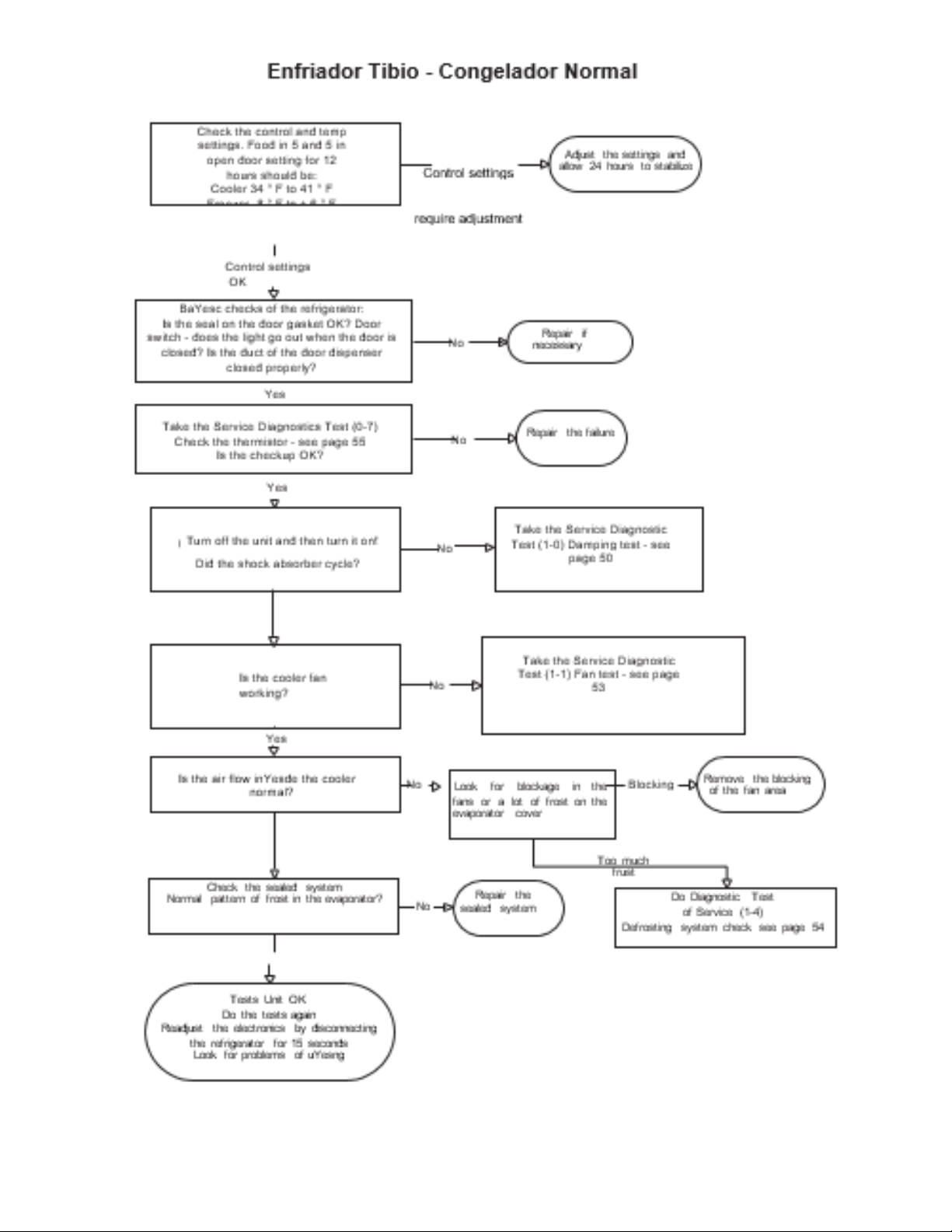
Warming Cooler - Warm Freezer (diagnostic board)……………………………………………………………………… 40
Warming Cooler - Normal Freezer (diagnostic table) ……….. . . . . . . . . . . . . . . . . . . . . . . . . . . . . . . . . . . . . . . . 41
Very Cold Cooler - Normal Freezer (diagnostic table)…………………………………………………………………….. 42
Warm Freezer - Normal Cooler (diagnostic table)…………………………………………………………………………. 43
Compressor Does Not Work (diagnostic chart). . . . . . . . . . . . . . . . . . . . . . . . . . . . . . . . . . . . . ……… . . . . . . . . . . . 44
Shock Absorber Door Does Not Open or Close (diagnostic chart) ………………………………………………………..45
Condenser Fan Does Not Work (Diagnosis Box) …………………………………………………………………………… 46
Evaporator Fan Does Not Work (Diagnosis Box) …………………………………………………………………………….47
Cooler Fan Does Not Work (Diagnosis Box) ………………………………………………………………………………… 48
A lot of Frost in the Evaporator (diagnostic table) …………………………………………………………………………….49
Thermistor test. . . . . . . . . . . . . . . . . . . . . . . . . . . . . . . . . . . . . . . . . . . ……………………………………… . . . . . . . . . 50
Thermistor values (table 3)
Efficient Use of the Diagnostic. . . . . . . . . . . . …………. . . . . . . . . . . . . . . . . . . . . . . . . . . . . . . . . . . . . . . . . . . . . . . . . 51
Page 32

Table 1. Causes of
Failure
Freezer bin
Cooler bin
Above
15°
Fanrenheit
High resistance thermistor freezer
Low resistance thermistor
evaporator Failure condenser fan
Failure evaporator fan
Heater defrosting locked
Fail in door switch
Main control board failing
Faulting wiring
Open dispenser lid
Leaking in door packaging
Half-closed door
Fail sealed system
Above
50 °
Fahrenheit
High-resistance in the thermistor of
the cooler compartment
Closed cushion
Failure cooling fan
Evaporator fan failure
Failure door switch
Main control board failing
Failed wiring
Leak in the door package
Half-closed door
Normal Cycle
(entre 14° y -14°
Fahrenheit)
Normal Cycle
(entre 49° y 33°
Fahrenheit)
Below 15°
Fahrenheit
Closed damper closed
Low-resistance in the circuit of the
thermistor of the freezer
Main control board failing
Below
32°
Fahrenheit
Open locked shock absorber
Low-resistance in the sensor
circuit of the cooler compartment
Main control board failing
Enviroment temperature below 60 °
Shock absorber failing
Auto-Diagnostics
To enter the Auto-Diagnostic mode, both screens of the temperature control panels should be illuminated. A screen can
be illuminated by pressing an attached temperature adjustment button. When both screens are illuminated, adjust the
cooler and freezer temperature settings to 5. Simultaneously press and hold all 4 temperature adjustment buttons for
approximately 3 seconds. A 0 flashing on the refrigerator and freezer display will indicate that the refrigerator is in the
Auto-Diagnostic mode.
To do the self-diagnostic test, locate the test in Table 2, Diagnostic Tests.
For temperature control panels with single-digit displays, the COLD temperature setting knob will increment the numbers
upward and the ENVIROMENT temperature setting knob will increment the numbers downward. Use the freezer
temperature adjustment buttons to enter the test code number on the freezer screen. Use the refrigerator temperature
adjustment buttons to enter the test code number on the refrigerator screen. When a test code has been entered, the
screens will flash to confirm the test. Press the HOLD button for 3 seconds to start the test.
For 3-digit temperature control panels, the COLD temperature button will increase the numbers down and the enviroment
temperature button will increase the numbers upwards. Use the freezer temperature adjustment buttons to enter the
code number of the freezer screen. Use the refrigerator temperature adjustment buttons to enter the refrigerator's screen
code number.
After entering a test code, the screen will flash to confirm the test code. Press any button other than the temperature
adjustment button to begin the test.
Page 33

When the test has been completed, do one of the following:
• Enter the code 1 5 to completely reset the system
• Enter the code 1 6 to exit diagnostic mode. The temperature control panel is automatically reset.
• Unplug the refrigerator for at least 10 seconds. The test mode will end when the refrigerator is reconnected.
The test mode will automatically end after 15 minutes of inactivity.
Temperature Control Panel (One Digit Display)
- 31 -
9 ES MAS FRIO
9 ES MAS FRIO
TIBIO
MAS FRIO
TIBIO
MAS FRIO
AJUSTE TEMP REFRIGERADOR
AJUSTE TEMP CONGELADOR
Page 34

- 32 -
Communication Tests (0 2, 0 3 or 0 4)
A communication test will display the test code while checking the communication. When the test is finished,
the freezer display will show a P (pass) or an F (fault) for 2 seconds. After 2 seconds, the screens will show
the test code. At this time, you can enter a new test code.
Self-Test Temperature Control Panel (0 6)
This test applies only to the temperature control board inside the cooler compartment. When the Temperature
Control Panel Self-Test starts, all the LEDs and numerical segments on the screen will light up. When the
SAFE THAW button is pushed, all 3 LEDs for safe defrosting should be turned off. When the QUICK CHILL
button is pressed, all 3 LEDs for quick cooling should be turned off. Continue this procedure for each pair of
LED / button on the screen. The coldest key is to turn off seven-segment LEDs.
The warmer key is to turn off the Adjustment LED for both the freezer and cooler compartments.
To exit the Temperature Control Panel Auto-Test, both refrigerator temperature and adjustment keys must
be pressed simultaneously for 3 seconds. This can be done at any time to exit the test.
Table 2. Diagnostic Tests
Freezer
screen
Fridge
screen
Mo
de
Comment
0
2
Communication of the control
panel of temperature to the main
control panel
P on the CG screen if it is OK
F on the CG screen if it is not OK
0
3
Communication of the
temperature control panel to the
board disp.
P on the CG screen if it is OK
F on the CG screen if it is not OK
0
4
Communication of the board
disp. main control board
P on the CG screen if it is OK
F on the CG screen if it is not OK
0
6
Self-test temperature control
panel
See Self-Test Temperature Control Panel on page 32.
0
7
Self-test of the control system
and sensor
See Self-Test Control and Sensor on page 33.
1 0
Open shock absorber
Shock absorber will open, brief pause and then close.
1 1
Speed fan test
Each fan works for 10 secs. then for
1
2
100% running time
This mode operates the sealed system 100% of the time
for 1 hour.
1
3
Between pre-cooling
This places the freezer in the pre-cooling mode.
1
4
Defrost entity
This will put the refrigerator in the defrost mode. If the
cabinet is not cold when it is run, this mode can do it
extremely quickly. The cooler will return to normal
operation by itself.
1
5
Reset fridge
It causes a readjustment of the system.
1
6
Out of Test Mode
It causes the system to exit the test mode and readjust
the temperature control panel.
1
7
C/F Degrees
Refrigerator temperature adjustment keys can be used to
change the display from F to C or C to F.
Page 35

- 33 -
Dispenser Board
There is no self-diagnostic test for the dispenser board. The operation of the dispenser board is tested by
pressing each button and checking its proper operation.
Self-Test Sensor and Control System (0 7)
This test checks all five thermistors located through the unit. Once the test is started, the test code (0 7) will
stop flashing and the thermistor test results will appear on the freezer screen in the test order listed below.
The sequence number of the thermistor test will not be shown on the screen.
If the unit is not equipped with the Quick Cool option, the third thermistor (rapid cooling) will show 0 and three
audible beeps will sound on the temperature control panel. This is not a fault if the unit is not equipped with
the option of Fast Cooling.
Thermistor test results:
P = Pass
0 = Fail
S = Short to 5 VDC
B = Bad amplifier
The sequence of the thermistor test is:
1. Top cooler thermistor
2. Lower cooler thermistor
3. Quick cooling thermistor (0 displayed if the unit is not equipped with the Quick Cool option)
4. Evaporator thermistor.
5. Freezer thermistor.
Note: The results of the thermistor test will appear in the sequence shown above. The number of the
thermistor test sequence will not be shown on the screen.
Page 36

- 34 -
Main Control Board (Low-Voltage Sid)
1
- Black
2
- Red
3
Blue
4
- Purple
5
- White
1 – Blue/Red
2 - Yellow
3 – Red / White
4 – Blue/ White
5 - Blue
J4 J3 J1
J2
8 - Red
7 – Not used
6 – Black/ White
5 - Yellow
4 – Yellow/Black
3 - White
2 – Blue/White
1 - Blue
GEA00906
PROCESSING
UNIT
SALIDAS VENTILADOR
SELECCION
MODELO
THERMISTO
R
ENTRADAS
CODIFICADOR
ENTRADAS
SERPENTINES
AMORT.
COMUNICACION
ENTRADA/SALIDA
ENTRIES
TIME ON WARMER DEFROST
(MINUTES)
TIME COMPRESSOR
OPERATION (MINUTES)
OPEN DOORS ACCUMULATED
ENF AND CG (MINUTES)
- Yellow
– Red/Black
White-brown
4 – Blue/Yellow
1 COMM
2 +12V
3 -COM
4 DI
5 DO
1
J4
5 1
J3
1
10
J2
1 8
J1
1
J5
9 6
Page 37

- 35 -
Main Control Board (Side 120-VAC)
J7
1
- Beige
2
- Silver
3
- Yellow
4
–Red/White
5
-Blue/White
6
-Purple
7
- Red
8
– Not used
9
- Orange GEA00907
UNIDAD DE
PROCESAMIENTO
SALIDAS
COMPRESOR
Y
DESCONG.
SALIDAS
SWITCH
PUERTA
SALIDAS
ENFRIAMIEN-TO
DESCONGELACION
PRE-ENFRIA-
MIENTO
L1
COMP
DESCONG
J8 J9 LINEA J4
K4
COMP
J12 PAN_HTR
N
K3
DESCONG.
J6
DFZ
DFF
OCH
COMUN
AGUA
TRITUR.
TALADRO
2 1
K5
QC
J7
K7
PAILA/CALT
K1
TALADRO
K2
C/CR
K6
AGUA
Page 38
- 36 -
Main Control Board Locator Box (Low-Voltage Side)
Connector
Pin
Wire
color
Component
Termination
Pin-to-Pin Voltage
Reading
J1
1
Blue/Red
Thermistor # 1
Cooler
J1 pin 1 to pin 5 = 2.8
to 3.5 VDC
J1
2
Yellow
Thermistor # 2
Cooler
J1 pin 2 to pin 5 = 2.8
to 3.5 VDC
J1
3
Red White
Freezer thermistor
J1 pin 3 to pin 5 = 2.8
to 3.5 VDC
J1
4
Blue/White
Evaporator
thermistor
J1 pin 4 to pin 5 = 2.8
to 3.5 VDC
J1
5
Blue
Supply voltage
thermistor (5 VDC)
J1 pin 5 to J4 pin 3 =
5 VDC
J2
1
Blue
Tachometer of the
evaporator fan.
J2 pin 1 to pin 3 =
6.3 VDC
J2
2
Blue/White
Fan inlet
J2 pin 2 to pin 3 =
12 VDC
J2
3
White
Common fan
J2 pin 3 to pin 8 =
12 VDC
J2
4
Yellow/Black
Evaporator fan
J2 pin 4 to pin 3 = 12.4
VDC (high speed),
8 VDC (low speed)
J2
5
Yellow
Common fan
J2 pin 5 a pin 3 = 13.4
VDC (ventilador del cond
es de una velocidad)
J2
6
Black/White
Evaporator fan
J2 pin 6 a pin 3 = 0 VDC
(high speed), 3 VDC (low
speed)
J2
7
Not in use
Non applicable
Non applicable
J2
8
Red
Supply of energy to
the fan (12 VDC)
J2 pin 8 to pin 6 =
13.4 VDC (high vel), 9
VDC (low vel) J2 to 8
to J4 pin 3 = 13.4 VDC
Continues in next page.
Page 39
- 37 -
Main Control Board Locator Box (Low-Voltage Side)
Connecto
r
Pin
Wire
color
Component
ending
Pin-to-Pin
Voltage Reading
J3
1
Yellow
Shock absorber
J3 pin 1 to J4 pin 3 =
Stagnating voltage2.3
VDC Voltage running 6.0
VDC
J3
2
Red/Black
Shock absorber
J3 pin 2 to J4 pin 3 =
Stagnating voltage2.3
VDC Voltage running 6.0
VDC
J3
3
White/Brown
Shock absorber
J3 pin 3 to J4 pin 3 =
Stagnating voltage2.3
VDC Voltage running 6.0
VDC
J3
4
Blue/Yellow
Shock absorber
J3 pin 4 to J4 pin 3 =
Stagnating voltage2.3
VDC Voltage running 6.0
VDC
J4
1
Black
Common dispensing
board transmits /
receives
See the scheme
J4
2
Red
Common dispensing
board
12 VDC
See the scheme
J4
3
Blue
Common grounding
board
See the scheme
Continues on next page.
Page 40

- 38 -
Main Control Board Locator Table
(Side 120-VAC)
Connector
Pin
Wire
Color
Component
ending
Pin-to-Pin Voltage
Reading
J7
1
Beige
Drill motor
J7 pin 1 a J7 pin 9 +
120 VAC
J7
2
Silver
Selenoid cube
J7 pin 2 a J7 pin 9 +
120 VAC
J7
3
Yellow
Water valve
J7 pin 3 a J7 pin 9 +
120 VAC
J7
4
Red/White
Interlock drilling
motor
J7 pin 4 a J7 pin 9 +
120 VAC
J7
5
Blue/White
Quick cooler heater
J7 pin 5 a J7 pin 9 +
120 VAC
J7
6
Purple
Door light cooler
feedback switch
J7 pin 6 a J7 pin 9 +
120 VAC
J7
7
Red
Light freezer door
switch feedback
J7 pin 7 a J7 pin 9 +
120 VAC
J7
8
No se usa
Not used
No se usa
J7
9
Orange
Neutral
Neutral
Page 41

Page 42

Page 43
Page 44

Page 45

Page 46

Page 47

Page 48
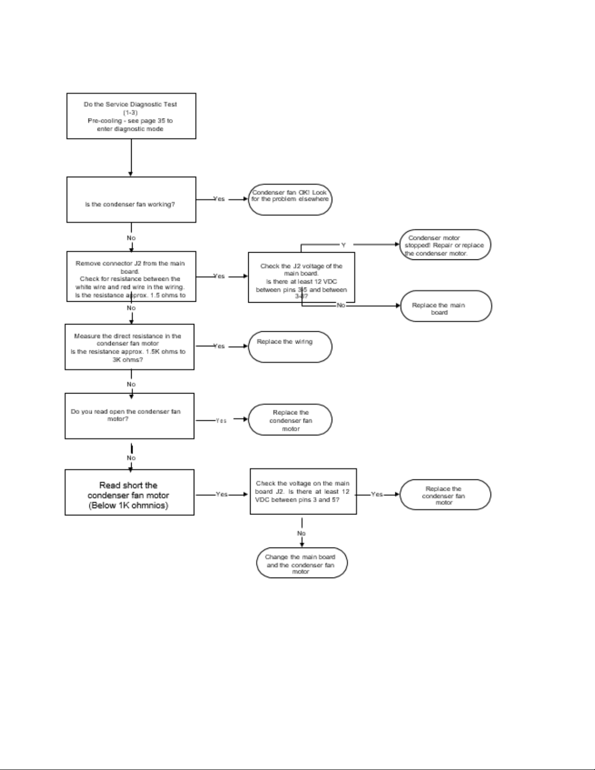
The Condenser Fan Does Not Work
Page 49

Page 50

Page 51

Page 52

Page 53
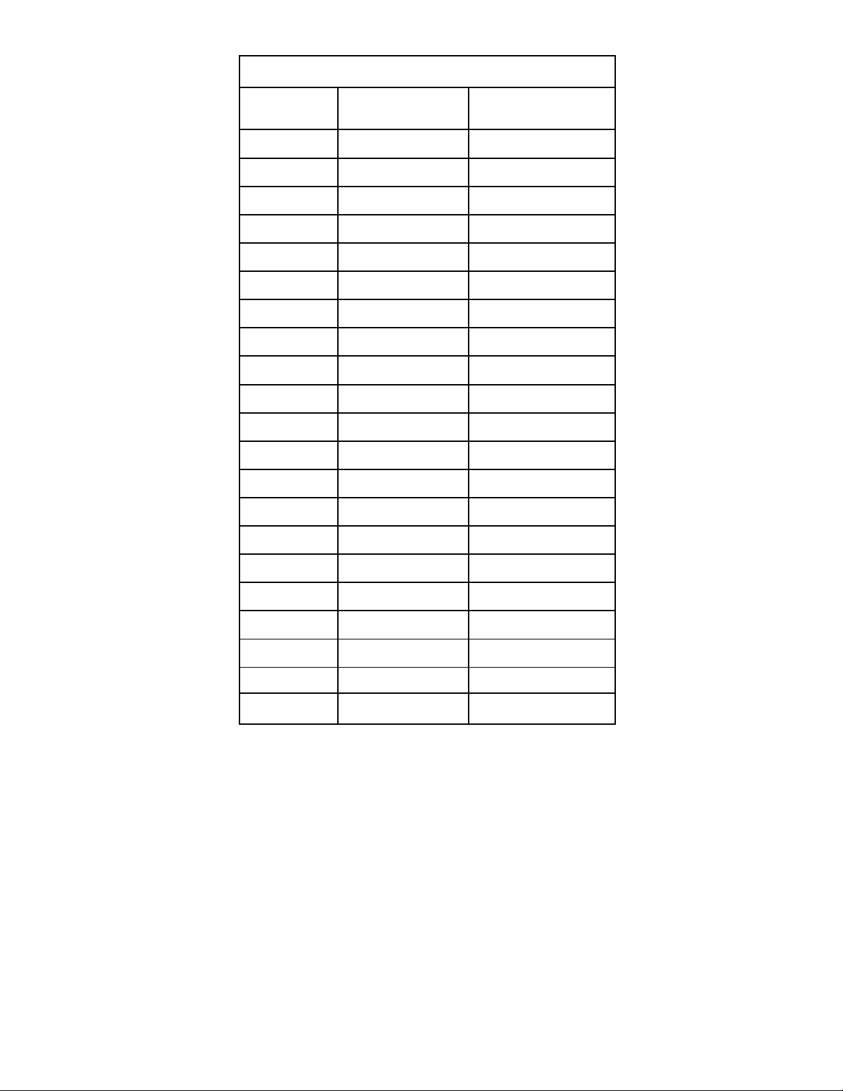
Table 3. Thermistor values
Temperature
Degrees (C)
Temperature
Degrees (F)
Resistence in
Kilo-Ohmnios
-40
-40
166.8 k
-35
-31
120.5 k
-30
-22
88 k
-25
-13
65 k
-20
-4
48.4 k
-15
5
36.4 k
-10
14
27.6 k
-5
23
21 k
0
32
16.3 k
5
41
12.7 k
10
50
10 k
15
59
7.8 k
20
68
6.2 k
25
77
5 k
30
86
4 k
35
95
3.2 k
40
104
2.6 k
45
113
2.2 k
50
122
1.8 k
55
131
1.5 k
60
140
1.2 k
NOTE: The resistance of the thermistors has a negative coefficient. As the temperature increases, the resistance of
the thermistor decreases.
- 51 -
Page 54

- 52 -
Component Location and Connector Views
Switch
freezer
light
Light
Evaporator
thermistor
Evaporator
Freezer
thermistor
Evaporator
fan
Defrost
thermistor
Heater defrost
Page 55

- 53 -
Shock absorber
Cooler thermistor
Cooler
lights
Cooler
light
switch
GEA00980
Page 56

- 54 -
GEA00977
Condenser
fan
"Jelly Roll"
Page 57

- 55 -
PROCESAMIENTO
ENTRADAS VENTILADOR
SELECCION
MODELO
ENTRADAS
THERMISTO
R
ENTRADAS
CODIFICADOR
SERPENTINES
AMORTIGUA-
DOR
COMUNICACION
ENTRADA/SALIDA
Main Control Board (Low-Voltage Side)
1 - Black
2 - Red
3 -
Blue
4 - Purple
5 - White
1 - Blue / Red
2 - Yellow
3 - Red / White 4
- Blue / White 5 Blue
J4 J3 J1
J2
8 - Red
7 - No es Usado
6 - Black / White 5
- Yellow
4 - Yellow / Black 3
- White
2 - Blue / White
1 - Blue
GEA00906
NOTE: For more information see the Main Control Board Location Tables in the Diagnostics chapter
1 COMM
2 +12V
3 -COM
4 DI
5 DO
1
J4
5
1
J3
1
10
J2
1
8
J1 1 J5
9
6
Page 58
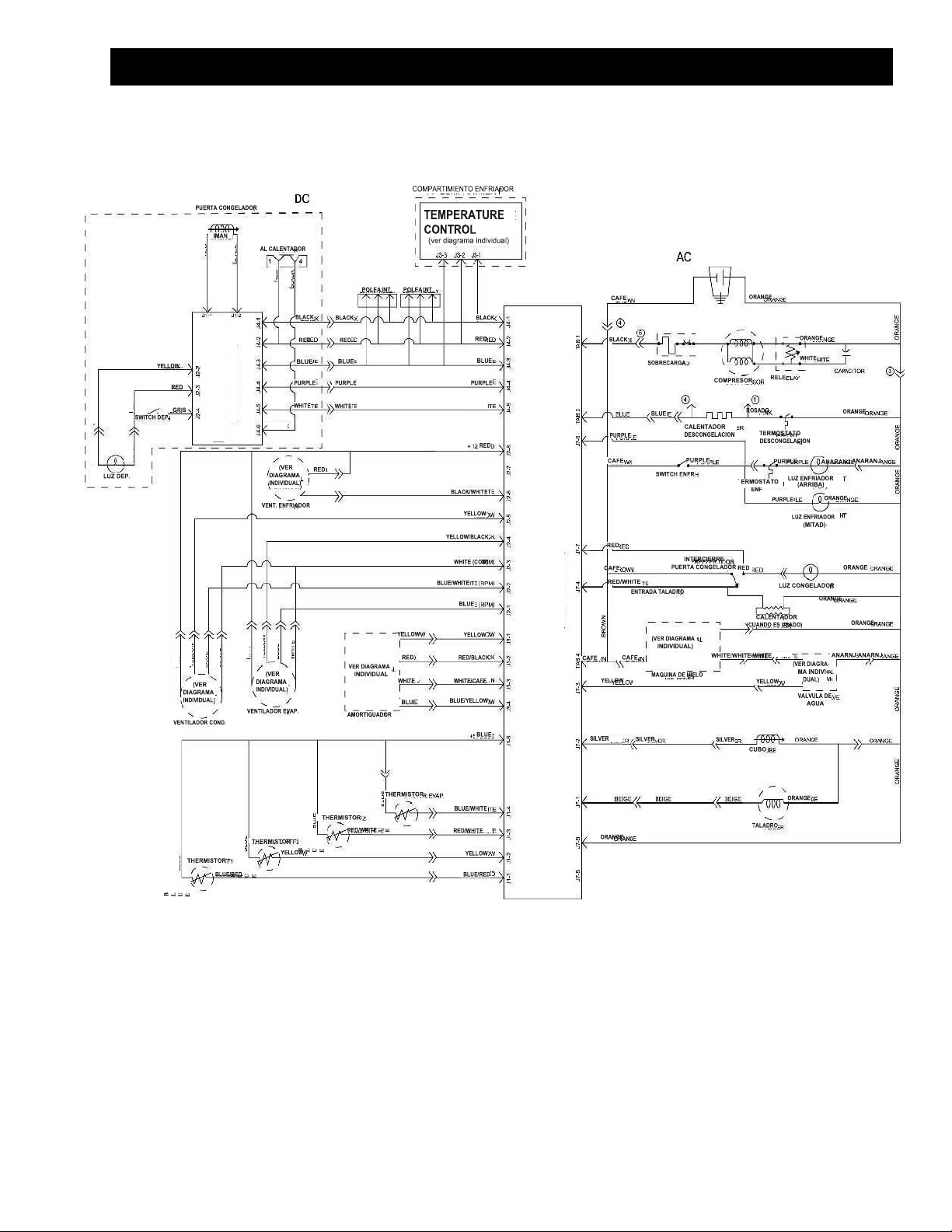
- 56 -
Diagrams
WHITE
YELLOW
BLACK RED RED YELLOW RED BLUE WHITE
PANEL SCREEN
VER DIAGRAMA
INDIVIDUAL
BLACK RED YELLOW RED
BLUE
WHITE BLACK
PRINCIPAL CONTROL PANEL
VER DIAGRAMA
INDIVIDUAL
ORREJETA 4 OREJETA 2 OREJETA 1
CAFE
ORANGE ORANGE ORANGE ORANGE ORANGE
Page 59
- 56 -
Adjustable Main Control (Side 120-VAC)
J7
1
- Beige
2
- Silver
3
- Yellow
4
- Red / White 5
- Blue / White 6 Purple
7
- Red
8
– Not used
9
- Orange GEA00907
NOTE: For more information see the Main Control Board Location Tables in the Diagnostics chapter.
PROCESSING
UNIT
SALIDAS
COMPRESOR
Y
DESCONG.
ENTRADAS
SWITCH
PUERTA
EXITS
DEFROST
PRE-
COOLING
COOLING
L1
COMP
DEFR
J8 J9 LINE J4
K4
COMP
J12 PAILA_CLT
N
K3
DESCONG.
J6
DFZ
DFF
OCH
COMUN
AGUA
TRITUR.
TALADRO
2 1
K5 QC J7
K7
PAILA/CALT
K1
TALADRO
K2
C/CR
K6
AGUA
Page 60

Thermistor location
Evaporati
on
Thermist
or (Located in
the
evaporator)
Freezing
Thermist
or
Cooling
Thermisto
Page 61

Page 62

- 59 -
ANARANJA
GRIS
CUANDO
USADO
SWITCH
SELECTOR
CONTROL
MODULO
A MAQUINA
DE HIELO
LUZ SWITCH
CUANDO ES
USADO
WHITE
CAFE
SILVER
ORANGE
ORANGE
VERDE
YELLOW
RED
ORANGE
A MOTOR
TALADRO &
SELENOIDE
LUZ
CONGELADOR
ORANGE
RED
RED
ELECTRO
YELLOW
LUZ DISPEN-
SADOR
ES
DO
TECLA
ORANGE
ROSADO
WHITE
BLU
E
SWITCH INTERCIERRE
PUERTA CONGELADOR
CAFE
RED/WHITE
LAMPARAS
ENFRIADOR
IMAN
CALENTADOR EMP.
CAFE
GRIS
SWITCH
CALENTADORES
DESCONG.
ORANGE
BLACK
ORANGE
PURPLE
SWITCH LUZ
ENFRIADOR
CAFE
PURPLE
ORANGE
CORDON
ENERGIA
AL ALAMBRADO
MAQUINA
CAFE
YELLOW
ORANGE
AL ALAMBRADO
DEL GABINETE
WHITE
VALVULA MAQUINA DE HIELO
BLACK
RED
BLUE
PURPLE
WHITE
BLACK/WHITE
NO SE USA YELLOW
RED
GRIS
AL ALAMBRADO
DEL GABINETE
ORANGE
VERDE/YELLOW
SOBRECARGA
WHITE
RELE
ORANGE
CAPACITOR DE OPERACION
LAMPARA
ENFRIADOR
TERMOSTATO
DESCONG.
RED
WHITE
BLACK
Page 63

- 60 -
Illustrated Parts of the Catalog
The scanned views of PSS25MGMABB are for general reference.
Always refer to the specific model for the latest piece information.
Page 64

- 61 -
IMPORTANT NEWS:
Additional parts are required to
install the evaporator. See the
EVAPORATOR INSTRUCTIONS page
of this model for additional part
numbers or replacement options.
Page 65

- 62 -
HERRAMIENTA LOKRING
CONECTOR
Bronce
PROTECTOR DE CALOR
SOLDADOR
There are two approved methods to change the evaporator. The
Lokring method does not require welding, since it uses tight
mechanical connections. The heat shield uses the traditional
soldering method, but gives protection to the upper liner while
welding the evaporator connections in the freezer compartment.
Always add a new drying filter when repairing the sealed system.
Follow each step of the instructions included with the evaporator
replacement.
.
LOKRING METHOD
Lokring is a method to install the evaporator in the freezer
without using a torch. It uses a mechanical connection
instead of a soldered connection. Apply a few drops of
LokPrep (a special cleaning solution and seal) to the
terminals of the pipe you wish to join. The Lokring tool
compresses the connector to ensure a tight mechanical
connection. The parts shown on the right are required to
use the Lokring replacement method.
For additional information on how to use the Lokring, call
1-800-848-7722 & order publication # 31-9067 (Lokring
Repair Procedures Manual) and Publication # 31-9066
(VHS Video Cassette Lokring Repair Procedures)
HEAT PROTECTOR METHOD
The heat protection kit is used to prevent damage to the
refrigerator liner when soldering the evaporator in the
sealed system. See the instructions included in the heat
protection kit. The kit comes with enough heat absorbing
paste, soldering iron and adhesive to finish four repairs.
Ref No. Pieza Número Descripción
228 WR85X10022 Conjunto Lado Bajo
PASTA
 Loading...