

Page 1

manual de uso y cuidado
estufas de piso
modelos
lea cuidadosamente este instructivo antes de instalar su
estufa.
No. de parte 183D9489P024
L1700BBE
L1700LLE
L1700TBBE
1700TBE
1700TBBE
1700TLE
1700TLLE
J1700TBE
JL1700TBBE
PREM700BBE
PREM700LLE
JEM1748BBE
JEM1758BE
EM800CBCE
EM800CNCE
DL1750TBBE
EM1765
EM1770BBE
JEM1770BBE
EM1770NNE
EM1700BE
EM1758BBE
JEM1770XO
EM1771BBE
1
Page 2

¡Felicidades!
Usted ha adquirido un producto de la más alta calidad, diseño y tecnología.
Debido a que en estamos comprometidos con satisfacer las expectativas y necesidades de nuestros clientes;
trabajamos en brindarle el mejor servicio, con productos
seguros y altamente competitivos a escala internacional.
respalda la garantía de su estufa y atiende sus requerimientos postventa a través de Serviplus, la empresa líder en servicio de Línea Blanca en Latinoamérica.
Con orgullo, agradecemos su preferencia y confianza.
2
Page 3

Indice de Contenidos
1. Características por Modelo
1.1 Partes y Accesorios................................................................................. 4
2. Instrucciones de Instalación
2.1 Condiciones del Espacio.......................................................................... 5
2.2 Nivelación................................................................................................ 6
2.3 Instalación de Copete............................................................................. 6
2.4 Conexión de gas...................................................................................... 7
2.5 Conexión eléctrica................................................................................... 8
2.6 Instalación de Quemadores.................................................................... 9
2.7 Instalación de Parrillas Superiores........................................................ 10
2.8 Puerta del Horno................................................................................... 10
2.9 Instalación de Parrillas de Horno......................................................... 10
3. Operación
3.1 Seguridad............................................................................................... 11
3.2 Capelo.................................................................................................... 12
3.3 Encendido de Quemadores.................................................................. 12
3.4 Encendido del Horno............................................................................ 14
3.5 Encendido del Asador Bajo................................................................... 15
3.6 Reloj ...................................................................................................... 15
4. Mantenimiento
4.1 Guía de limpieza y cuidado.................................................................. 16
5. Recomendaciones de Cocinado
5.1 Temperaturas del Horno....................................................................... 19
5.2 Posiciones de Alimentos en el Horno.................................................. 19
5.3 Posiciones de Alimentos en el Asador.................................................. 20
5.4 Recomendaciones Generales................................................................ 20
6. Diagramas eléctricos......................................................... 21
7. Problemas y Soluciones..................................................... 23
8. Características por modelo............................................... 24
9. Póliza de Garantía.............................................................. 50
3
Page 4
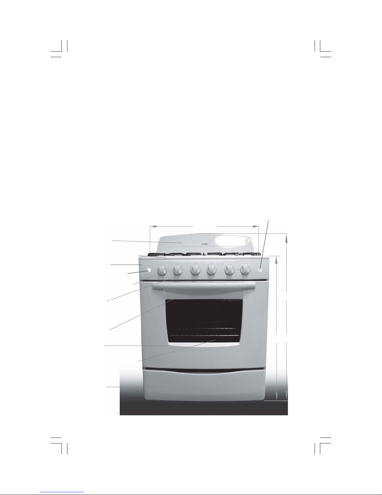
1.1 Partes y Accesorios
2 Parrillas laterales superiores de alambrón.
1 Parrilla central superior de alambrón.
1 Comal Porcelanizado.
1 ó 2 Parrillas de horno (según modelo).
Las siguientes características no aplica al modelo EM800
2 Soportes metálicos para copete.
4 Tornillos cabeza tipo cruz, en color negro.
4 Mariposas.
1 Charola asador (exclusivo para los modelos JEM1748, JEM1758, EM1765, EM1770, JEM1770
y EM1771).
Botón luz horno
(según modelo)
75,7
cm
Copete
Parrillas superiores
Cubierta
Botón encendido
Panel de Control
Perillas
Jaladera
Puerta
Parrillas del horno
Asador
4
108,2 cm
90,9 cm
Page 5
2. Instrucciones de Instalación
Guarde estas instrucciones para referencia futura.
Asegúrese de que su estufa sea instalada por personal calificado o por un técnico de
SERVIPLUS.
2.1 Condiciones del Espacio
Preparación
1 Retire todos los adhesivos y materiales de empaque, incluyendo películas plásticas que cu-
bren algunas partes de la estufa. Por ejemplo: Cubierta inoxidable.
Le recomendamos reciclar los empaques de cartón en depósitos especiales para este fin.
2 Retire los accesorios que vienen dentro del horno.
ANTES DE INSTALAR LA ESTUFA SOBRE UN PISO CUBIERTO DE LINOLEUM O CUALQUIER OTRO RECUBRIMIENTO SINTÉTICO, VERIFIQUE
QUE ESTE MATERIAL Y LOS MUEBLES QUE ESTÉN JUNTO A LA ESTUFA RESISTAN UNA TEMPERATURA DE 95 °C, SIN DEFORMARSE.
NUNCA INSTALE SU ESTUFA SOBRE UNA ALFOMBRA O CUALQUIER MATERIAL FLAMABLE.
PARA REDUCIR EL RIESGO DE INCENDIOS INSTALE SUS MUEBLES DE COCINA CONFORME AL DIAGRAMA DIMENSIONAL. EVITE INSTALAR GABINETES POR ENCIMA
DE LA ESTUFA A UNA DISTANCIA MENOR A LA ESPECIFICADA.
Localización
Le sugerimos no instalar su estufa en lugares expuestos a fuertes corrientes de aire.
En caso de que su estufa se encuentre cerca de una puerta o ventana, procure mantenerlas
cerradas mientras cocine.
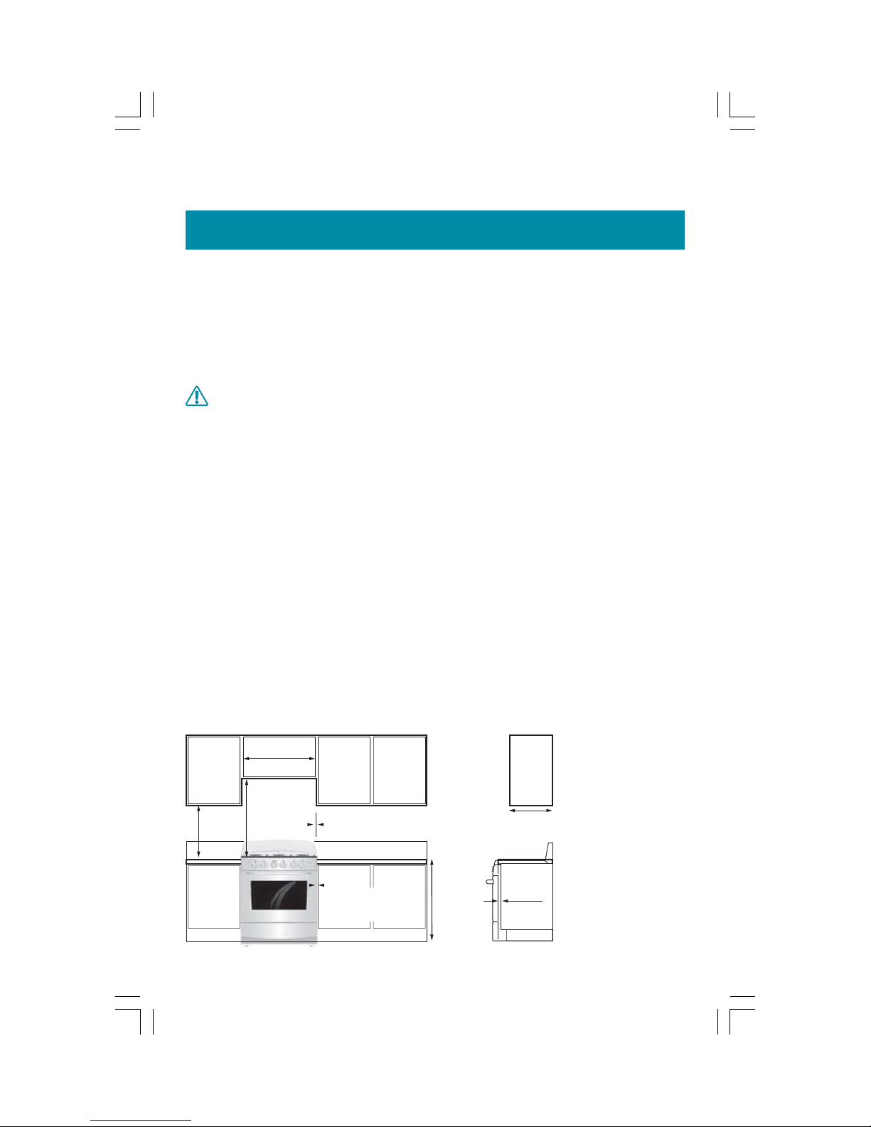
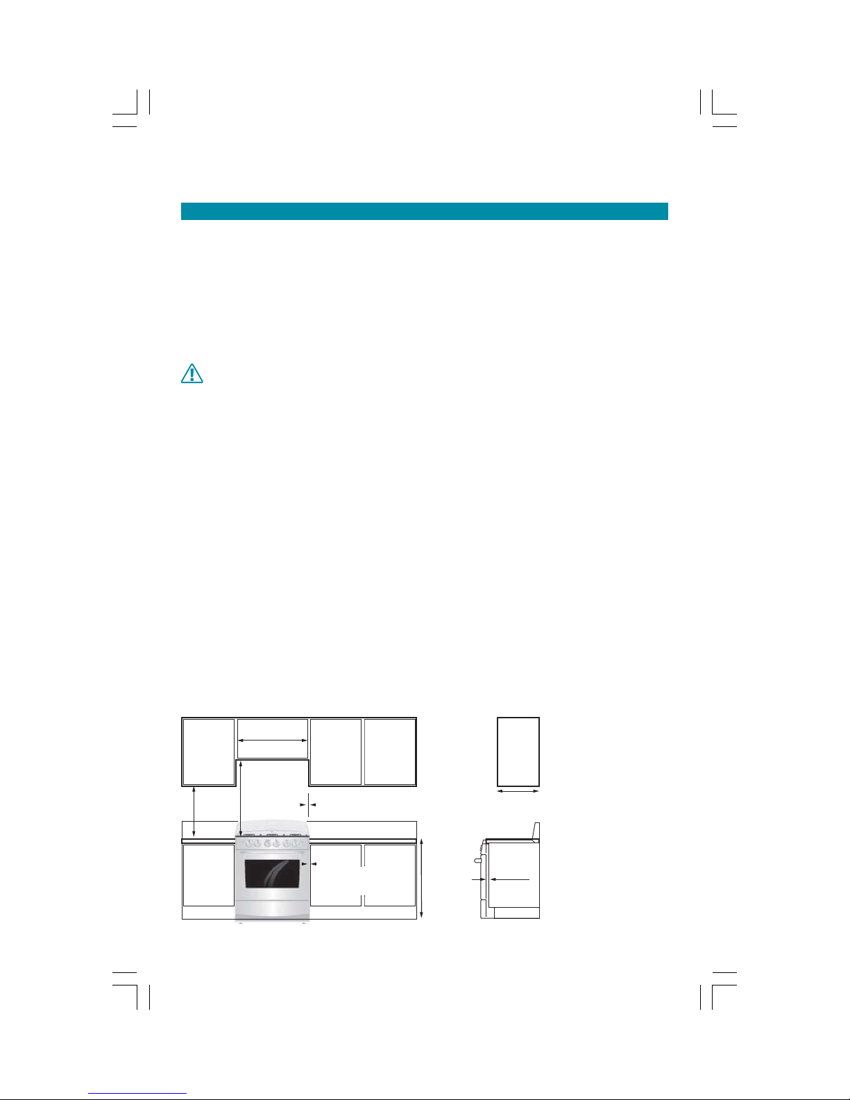
Dimensiones y espacios mínimos
En el esquema siguiente, se muestran las dimensiones mínimas de espaciamiento requeridas
para la instalación. Estas dimensiones deben respetarse.
76,2 cm
46 cm mín.
76 cm mín.
2,5 cm si se instala
junto a una pared
2 cm para gabinetes que
no rebasen la altura de la
cubierta ni el frente de la
estufa
91,5 cm
33 cm máximo
gabinete superior
0,6 cm de
rebase desde la
parte f rontal del
panel lateral,
hacia el f rente
del gabinete
5
Page 6
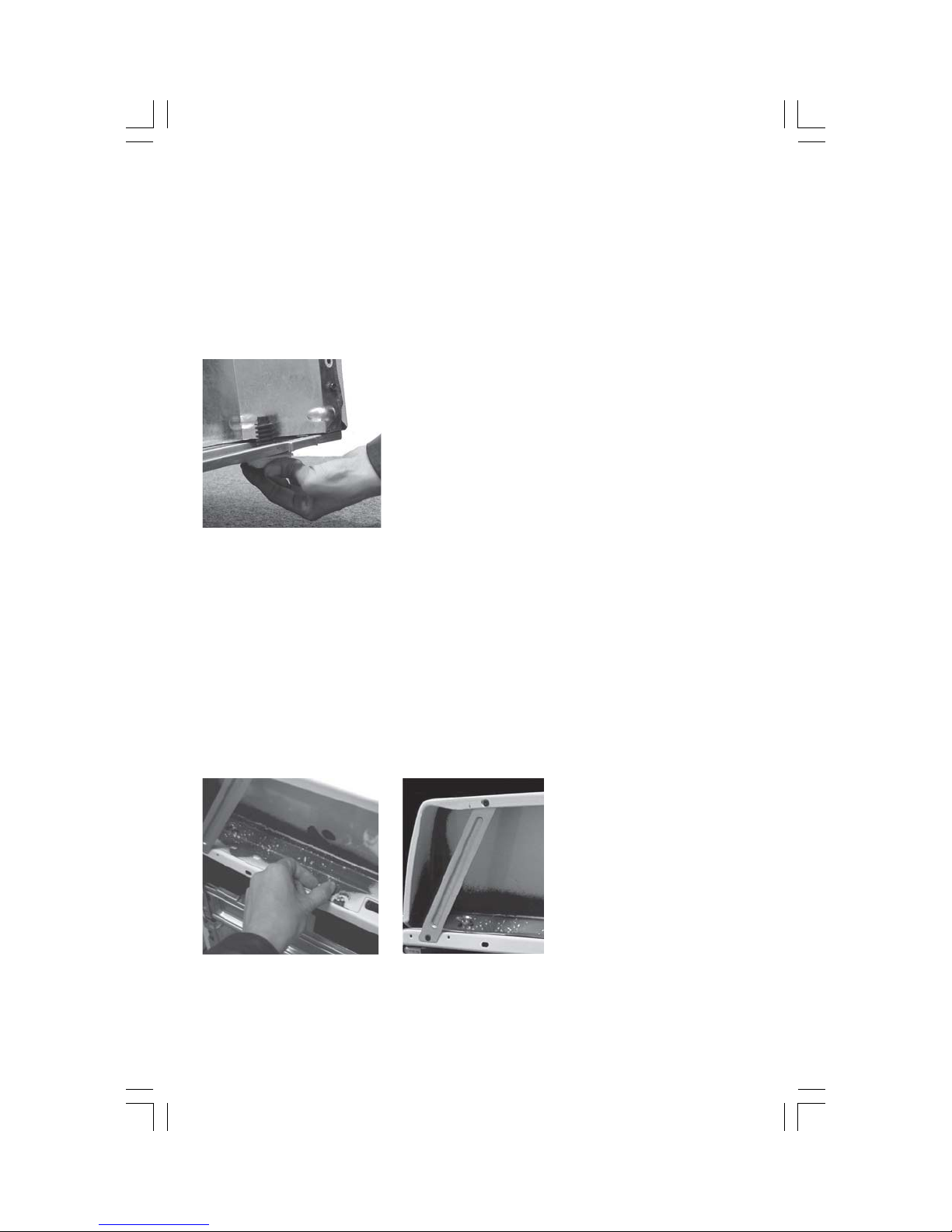
2.2 Nivelación
Recomendamos nivelar la estufa para un horneado parejo, antes de hacer
conexiones de gas y electricidad.
Su estufa cuenta con dos tornillos niveladores, ubicados en la parte posterior del piso de la
estufa. Sitúe la estufa en la zona donde vaya a ser instalada.
Coloque un nivel sobre las parrillas del horno.
Si observa que su estufa no esta nivelada, con la ayuda de otra persona, incline su estufa ha-
cia un lado y gire el tornillo. Repita la operación del otro lado para obtener la altura deseada.
2.3 Instalación del Copete
Paso 1
Desempaque el copete localizado en la parte posterior de la estufa.
Paso 2
Coloque el copete sobre la cubierta y cerciórese de que los orificios de ambas piezas, coincidan para que asiente bien el copete (ver fotografía 1).
Paso 3
Coloque los 4 tornillos de cruz, en la cara superior del copete y en la cara inferior de la cubierta, apriete bien con las mariposas.
fotografía 1 fotografía 2
Paso 4
Coloque los refuerzos metálicos en posición diagonal (ver fotografía 2).
6
Page 7
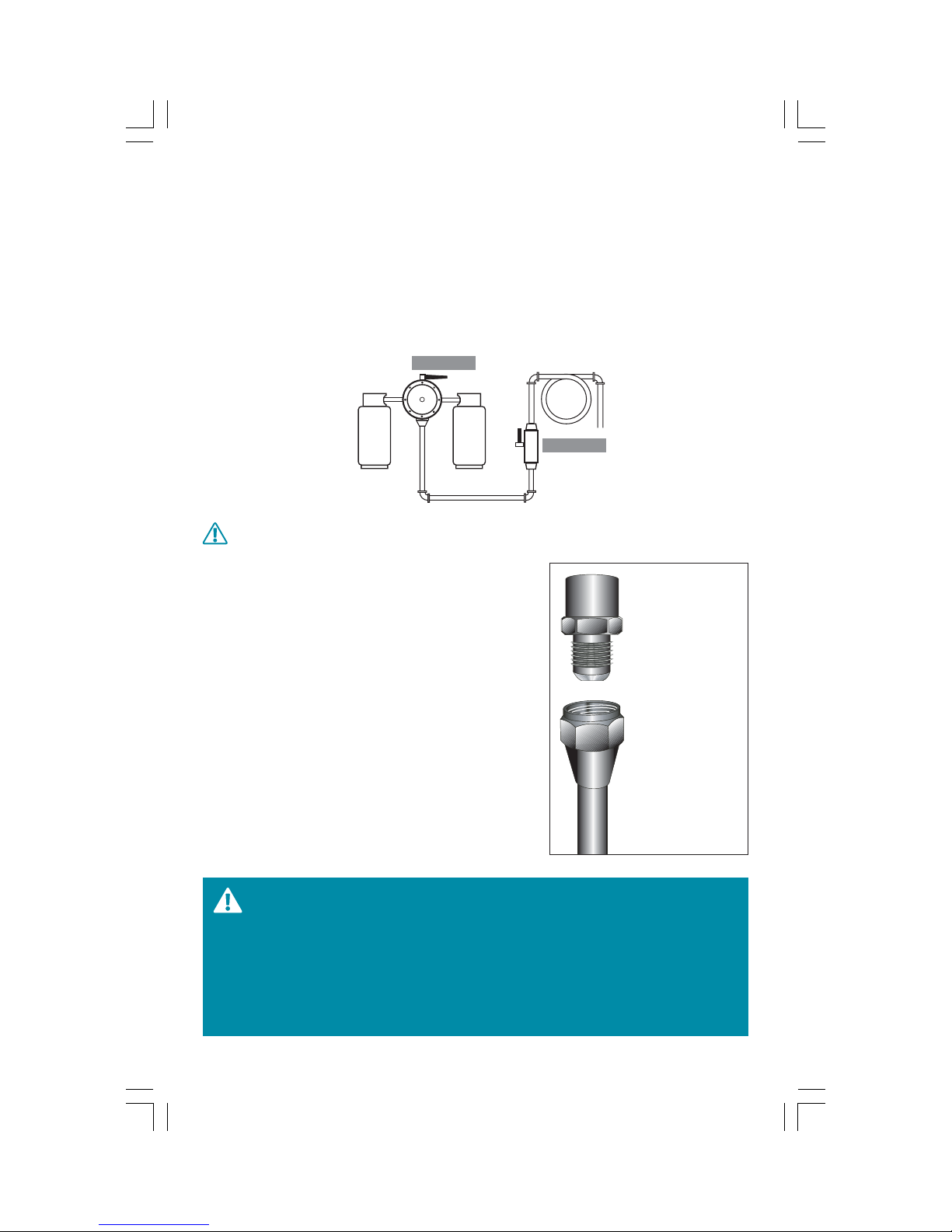
2.4 Conexión de gas
Asegúrese de que su hogar cuente con un regulador de presión de gas que
suministre la presión correcta.
1 Cierre la válvula principal del suministro de gas antes de desconectar la estufa a reemplazar
y déjela cerrada hasta que termine la conexión de la estufa nueva.
2 Instale una válvula de paso manual, a la línea principal de gas en un lugar de fácil acceso ,
fuera de la estufa. Cerciórese de que todos los que van a usar la estufa sepan cómo operar
esta válvula y cerrarla en caso necesario.
regulador
válvula
NO USE MANGUERAS DE PLÁSTICO PARA LA INSTALACIÓN DE GAS.
3 Para la instalación de su estufa, utilice un niple termi-
nal hembra de 9,5 mm (3/8") NPT a la salida del regulador y conéctelo a un tubo de cobre con tuercas cónicas de 9,5 mm (3/8").
4 Conecte la válvula de paso y el tubo de cobre en los
extremos con campanas de 9,5 mm (3/8"). El tubo
de cobre flexible y /o manguera deberán medir entre
1,20 m y 1,50 m y deberán resistir temperaturas mayores de 250 °C.
5 Cuando termine de hacer las conexiones, verifique
que todas las perillas del panel de control de la estufa, se encuentren en la posición de apagado y entonces abra la válvula principal del suministro de gas.
6 Use agua y jabón en todas las juntas y conexiones
para verificar que no existe alguna fuga.
Campanas 9,5 mm
(3/8")
Tuercas cónicas
9,5 mm (3/8")
Tubo de cobre
ESTE APARATO PUEDE USARSE CON GAS L.P. O CON GAS NATURAL. EN FABRICA FUE AJUSTADO PARA TRABAJAR CON GAS L.P.
Y ESTÁ DISEÑADO PARA FUNCIONAR A UNA PRESIÓN DE 2,75
kPa (11 in C.A.) EN CASO DE QUE SU INSTALACIÓN SEA PARA
GAS NATURAL, DEBERÁ TENER UNA PRESIÓN DE 1,76 kPa (7 in
C.A.)
7
Page 8
PARA ESTE ÚLTIMO CASO, UN TÉCNICO DE SERVIPLUS DEBE HACER LA CONVERSIÓN, ANTES
DE USAR SU ESTUFA; SIN CARGO PARA USTED. (VÁLIDO DURANTE EL PRIMER AÑO A PARTIR
DE SU COMPRA).
USE CONEXIONES NUEVAS PARA PREVENIR FUGAS DE GAS, INSTALE SELLADOR DE JUNTAS O
CINTAS ESPECIALES PARA ESTE FIN, EN TODAS LAS CONEXIONES EXTERNAS.
NO UTILICE FLAMA PARA DETECTAR FUGAS DE GAS.
AL MOVER SU ESTUFA, EVITE QUE LA CONEXIÓN DE GAS, SE ESTRANGULE O MUERDA, PARA
EVITAR FUGAS DE GAS.
CERCIÓRESE DE MANTENER LOS ALREDEDORES DE LA ESTUFA
LIBRES DE MATERIALES COMBUSTIBLES, GASOLINA Y OTROS
VAPORES O LIQUIDOS FLAMABLES.
2.5 Conexión eléctrica
Este aparato está diseñado para funcionar con un voltaje nominal
de 127 V ~ 60 Hz o bien 110 V ~ 50 Hz (Según modelo. Refiérase a los diagramas eléctricos).
Revise tener instalado en la pared un contacto adecuado y conectado a tierra, verificado por
un electricista calificado.
Si su estufa cuenta con luz interior en el horno, antes de utilizarla compruebe que la toma de
corriente esté apropiadamente conectada a tierra, y protegida por un interruptor térmico o
un fusible de 15 a 20 A.
Procure no conectar ningún otro aparato a la misma toma de corriente. El cable tomacorriente deberá estar libre de torsiones y evite el contacto con la parte posterior de la estufa. En
caso de necesitar una extensión deberá emplear cable de las mismas características del cable
tomacorriente.
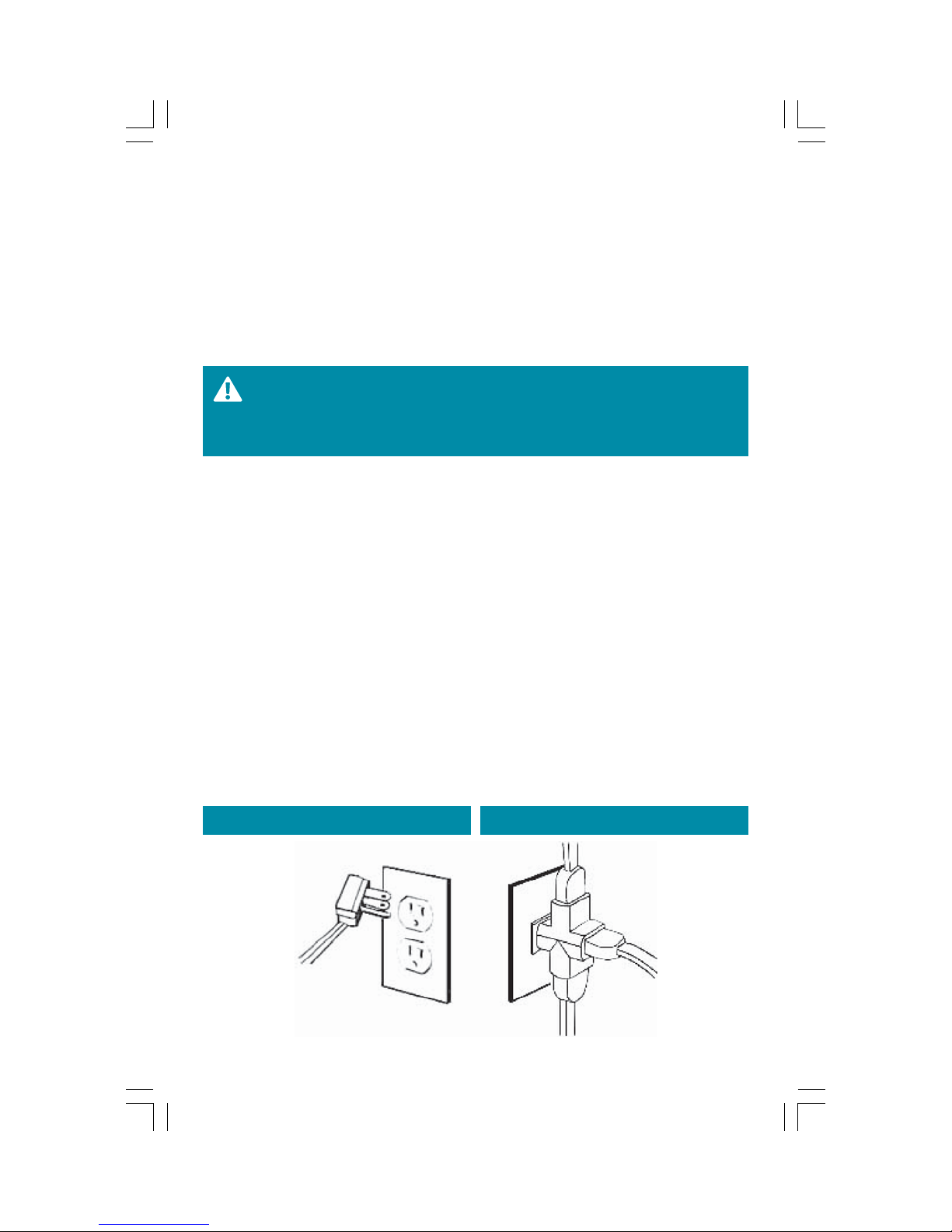
Nunca corte o elimine el pin de tierra que contiene la clavija.
CORRECTO INCORRECTO
8
Page 9
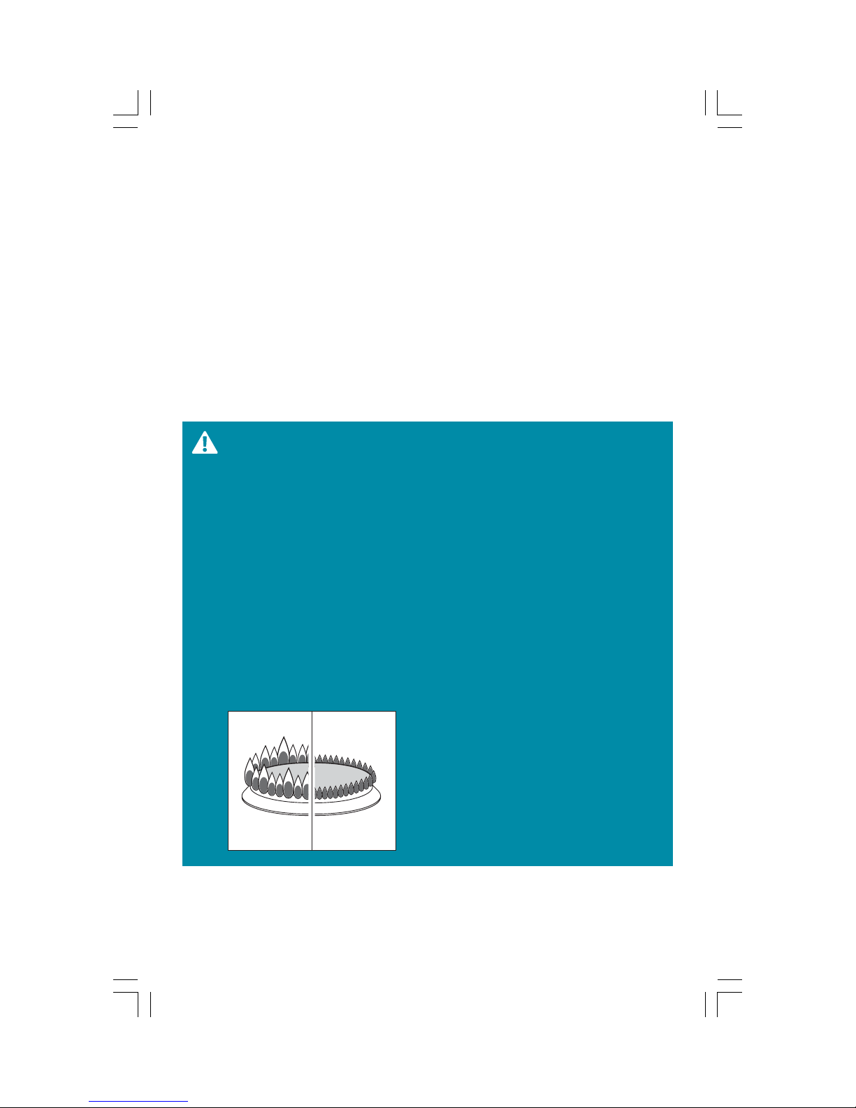
2.6 Instalación de Quemadores
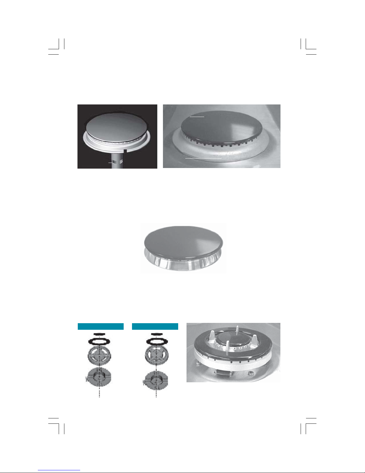
Verifique que el quemador y la tapa estén bien colocados conforme al
diagrama.
Las tapas porcelanizadas van arriba del cuerpo.
Tapa
porcelanizada
Cuerpo
Tubo mezclador
de aluminio
Quemadores Triple Ring
(Ver tabla de características)
Su estufa cuenta con un nuevo quemador, el cual se recomienda usar para el cocinado uniforme de sus alimentos, así como para recipientes grandes. Se deben tener en cuenta las siguientes consideraciones, para el correcto funcionamiento del quemador.
Antes de encender este quemador asegúrese de que las dos tapas estén bien colocadas en su
sitio. La parte esmaltada de las tapas deben estar colocadas hacia arriba. Tenga cuidado de
no golpear y/o jalar bujía, debido a que es más alta que las demás contenidas en su estufa.
Mantenga limpio el quemador de cualquier grasa o cochambre, evitando dejar residuos de
limpiador sobre la esprea que está en la base del mismo, ya que esto puede provocar obstrucciones y un mal funcionamiento del quemador.
INCORRECTOCORRECTO
Tapas de
quemadores
Base Quemador
9
Page 10
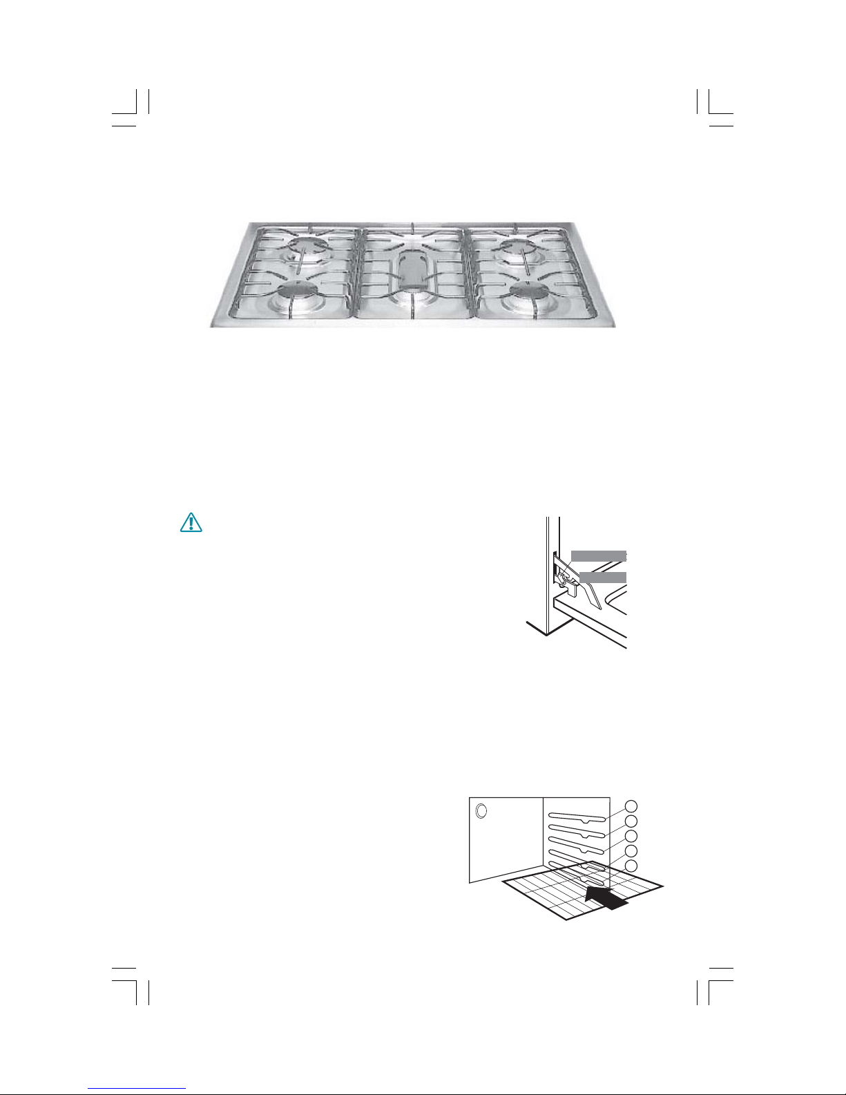
2.7 Instalación de Parrillas Superiores
A
B
C
D
E
Cada vez que requiera quitar las parrillas superiores, para darles limpieza; verifique colocarlas nuevamente, en su posición original (ver esquema).
2.8 Puerta de Horno.
La puerta del horno es removible para hacer más accesible el interior de la estufa.
Para retirarla, abra completamente la puerta, con ambas manos desplace los ganchos móviles
de las bisagras hacia adelante y asegúrese de que queden fijas, levantando ligeramente la
puerta.
Levante con las dos manos la puerta hasta sentir como sale fácilmente y jale hacia arriba.
Para colocarla nuevamente, centre los brazos de las bisagras en las ranuras inferiores del mar-
co metálico y mueva los ganchos hacia atrás para fijar el mecanismo.
TENGA CUIDADO DE NO COLOCAR LAS MANOS ENTRE LAS BISAGRAS Y LA ESTRUCTURA
DEL HORNO, YA QUE PUEDEN REGRESARSE
Gancho móvil
Bisagra
VIOLENTAMENTE Y ATRAPAR SUS DEDOS.
2.9 Instalación de Parrillas en el horno.
Las parrillas del horno están diseñadas con un tope que les impide ladearse y salir totalmente. Esto es especialmente cómodo cuando usted introduce y retira los alimentos del horno.
Para quitar las parrillas del horno, deslícelas hacia usted, levante la parte frontal y jálelas hacia afuera. Para reinstalarlas en su sitio, coloque la parrilla sobre el soporte (la parte curva de
la parrilla debe estar hacia el fondo del horno y debajo del tope), incline hacia arriba el frente y empújela hacia adentro del horno hasta que haya pasado el tope en la pared del horno.
Enseguida, baje la parte frontal y deslícela totalmente hasta el fondo.
El horno tiene cinco posiciones como se ilustra en el
esquema. En la sección de Recomendaciones de cocinado, se especifica a detalle el uso de cada posición
para hornear.
10
fondo
Page 11
3. Operación
3.1 Seguridad
Para su seguridad, tome en cuenta las siguientes recomendaciones:
SI HUELE A GAS:
1) ABRA LAS VENTANAS.
2) NO TOQUE LOS INTERRUPTORES ELÉCTRICOS.
3) APAGUE TODAS LAS FLAMAS CERRANDO LA VÁLVULA GENERAL DE PASO.
4) LLAME INMEDIATAMENTE A LA CENTRAL DE FUGAS O A SU
PROVEEDOR DE GAS.
NUNCA USE SU ESTUFA PARA CALENTAR UNA HABITACIÓN YA QUE
ESTO ES MUY PELIGROSO.
NO OBSTRUYA LA SALIDA DE LOS GASES DE COMBUSTIÓN DEL
HORNO Y ASADOR.
• No deje a los niños solos o sin vigilar cuando la estufa esté caliente o en operación. Pueden
quemarse seriamente.
• No permita que nadie se suba, se pare o se cuelgue de la puerta del horno o de la parte superior de la estufa.
• No permita que se acumule cochambre u otros materiales inflamables en o cerca de la estufa.
• Los aparatos de gas pueden causar una exposición a varias substancias tóxicas y/o dañinas
causadas principalmente por la combustión incompleta de gas natural o combustibles L.P.,
principalmente benceno, formaldehidos y hollín.
UNA INSTALACIÓN, AJUSTE, ALTERACIÓN O MANTENIMIENTO INADECUADO PUEDE CAUSAR DAÑOS Y ACCIDENTES.
UN QUEMADOR BIEN AJUSTADO, ES AQUEL QUE PRESENTA
UNA FLAMA AZULADA EN LUGAR DE AMARILLA.
PARA SU SEGURIDAD NO ALMACENE GASOLINA U OTROS FLUIDOS INFLAMABLES EN LA CERCANÍA O INTERIOR DE SU ESTUFA.
NO USE EL HORNO COMO ALACENA, LOS ARTÍCULOS GUARDADOS EN ÉL, PUEDEN INCENDIARSE.
NO INTENTE REPARAR O REEMPLAZAR CUALQUIER PARTE DE
SU ESTUFA, A MENOS QUE SE ESPECIFIQUE EN ESTE MANUAL.
11
Page 12
3.2 Capelo
(Aplica al modelo EM800)
Antes de usar su estufa, asegúrese de que las perillas estén en la posición
de apagado.
Levante el capelo, éste quedará en posición vertical sin que tenga que sostenerlo.
Este capelo no está diseñado para cocinar encima de él.
Las bisagras están cuidadosamente calculadas para disminuir el riesgo de ruptura de la placa
de cristal, ya que amortiguan el golpe que recibiría al chocar con la cubierta, en caso de que
accidentalmente se resbale. Sin embargo al levantarlo y bajarlo hágalo con mucho cuidado
ya que se trata de una pieza frágil.
LEVANTE EL CAPELO SIEMPRE QUE UTILICE LOS QUEMADORES SUPERIORES, ASÍ COMO EL
HORNO.
3.3 Encendido de Quemadores
ANTES DE ENCENDER LOS QUEMADORES RETIRE TODOS LOS
MATERIALES DE EMPAQUE QUE PROTEGEN A LA ESTUFA .
EL FUNCIONAMIENTO DE TODOS LOS QUEMADORES Y DEL
HORNO DEBERÁ SER REVISADO DESPUÉS DE QUE LA ESTUFA Y
LAS CONEXIONES DE GAS HAYAN SIDO DEBIDAMENTE VERIFICADAS CONTRA FUGAS.
CUANDO EL QUEMADOR SE ENCIENDA POR PRIMERA VEZ, LA
FLAMA ESTARÁ CASI HORIZONTAL Y SE ELEVARÁ LIGERAMENTE
FUERA DEL QUEMADOR, ADEMÁS SE ESCUCHARÁ UN SOPLIDO
O SILBIDO DURANTE 30 Ó 60 SEGUNDOS.
FÍJESE EN LA FLAMA, NO EN LA PERILLA MIENTRAS REDUCE LA
FLAMA DEL QUEMADOR.
Puntas
amarillas
12
CORRECTOINCORRECTO
Puntas azules
Page 13
Estufas de encendido por cerillos.
HIGH
LOW
(Aplica en los modelos L1700, L1700T, 1700T, J1700T, JL1700T, PREM700, JEM1748, DL1750T,
EM800 y EM1700)
1 Verifique que las perillas estén en la posición de apagado.
2 Encienda un cerillo.
3 Empuje y gire la perilla del quemador que quiere utilizar hacia la posición "HIGH".
4 Acerque con cuidado el cerillo prendido al quemador.
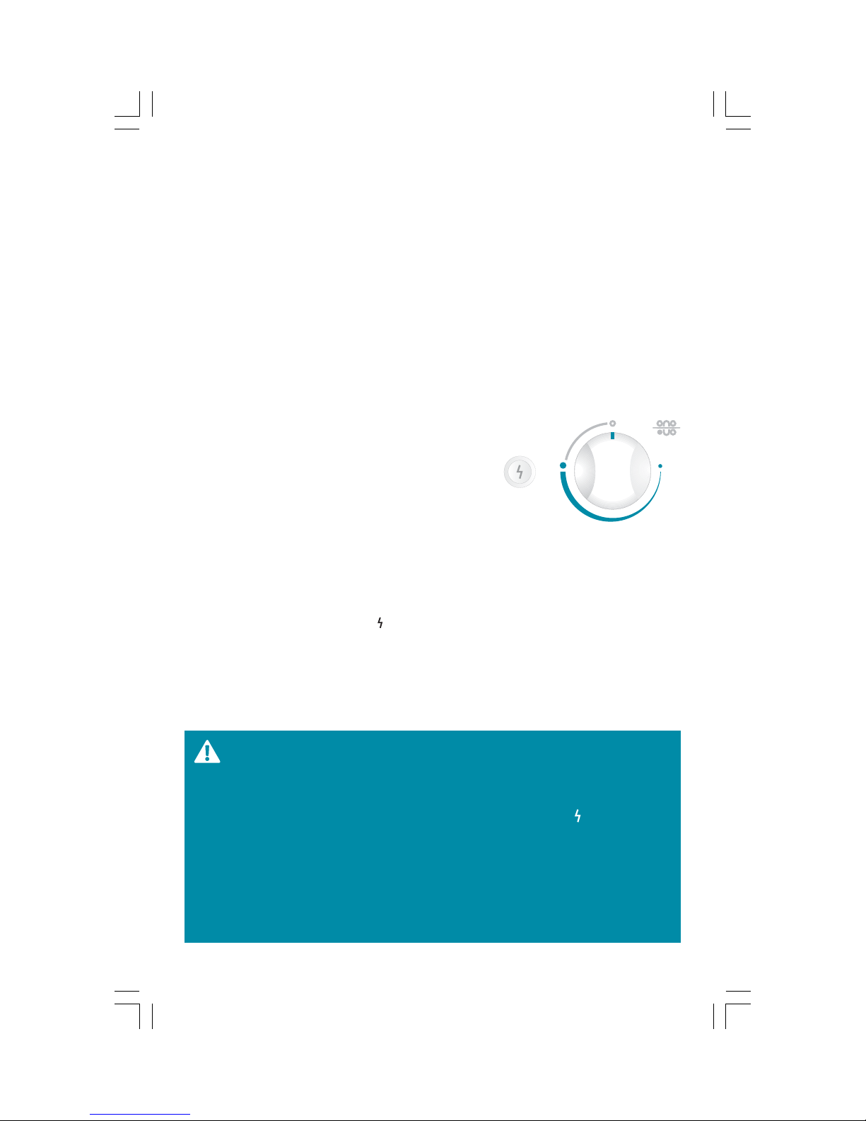
Estufas de encendido electrónico con botón.
(Aplica en los modelos JEM1758 , EM1765 y EM1758)
Al accionar el botón o girar la perillas en estos modelos, las bujías eléctricas se accionan automáticamente en todos los quemadores esto es un funcionamiento normal.
1 Verifique que las perillas están en posición de apagado, éstas deben estar afuera y cercióre-
se de que la estufa esté conectada a la corriente eléctrica.
2 Oprima el botón de encendido electrónico, indicado con
un signo de rayo, y manténgalo así accionado, escuchará un sonido característico de la bujía eléctrica del quemador.
3 Empuje la perilla que corresponda al quemador que de-
see utilizar y gírela a la posición de encendido (HIGH), el
quemador encenderá a los pocos segundos. Una vez encendido, suelte el botón y regule la flama girando la perilla.
Encendido electrónico integrado
(Aplica en los modelos EM1770, EM1771 y JEM1770)
Simplemente asegúrese de conectar la clavija tomacorriente al contacto. (Debidamente conectado a tierra.)
1 Empuje la perilla y gire en sentido contrario de las manecillas de reloj a la posición de en-
cendido marcada con el símbolo " ".
2 Se escuchará un ruido característico de la bujía eléctrica del quemador.
3 Después que el quemador encienda, gire la perillas para ajustar el tamaño de la flama de-
seada.
Al accionar la perilla, las bujías eléctricas se accionan automáticamente en todos los quema-
dores esto es un funcionamiento normal. Este sonido es normal y se debe a la mezcla de gas
y aire dentro del quemador.
EN CASO DE UNA FALLA DE ENERGIA ELÉCTRICA, USTED PUEDE
ENCENDER LOS QUEMADORES SUPERIORES ACERCANDO UN
CERILLO ENCENDIDO AL QUEMADOR, DESPUÉS GIRE CON MUCHO CUIDADO LA PERILLA A LA POSICIÓN "HIGH/ " TOME
PRECAUCIONES AL ENCENDER SU ESTUFA DE ESTA MANERA.
LOS QUEMADORES QUE ESTUVIERAN ENCENDIDOS ANTES DE
OCURRIR LA FALLA EN EL SUMINISTRO DE ENERGÍA ELÉCTRICA
PERMANECERÁN FUNCIONANDO NORMALMENTE HASTA QUE
SE APAGUEN.
13
Page 14
PARA ASEGURAR UN CORRECTO FUNCIONAMIENTO DEL COMAL, SIEMPRE DEBE REGULAR A FLAMA BAJA.
VERIFIQUE QUE SU TANQUE DE GAS NO SE ESTÉ TERMINANDO
YA QUE LAS PUNTAS AMARILLAS SON UN SIGNO DE ESTA SITUACIÓN.
SI DESPUÉS DE REALIZAR EL AJUSTE DEL REGULADOR DE AIRE
CONTINUAN LAS FLAMAS AMARILLAS, BUSQUE EL NUMERO TELEFÓNICO DE SERVIPLUS EN LAS ÚLTIMAS PAGINAS DE ESTE
MANUAL. ELLOS SE ENCARGARAN DE HACER LOS AJUSTES CORRESPONDIENTES.
3.4 Encendido de Horno
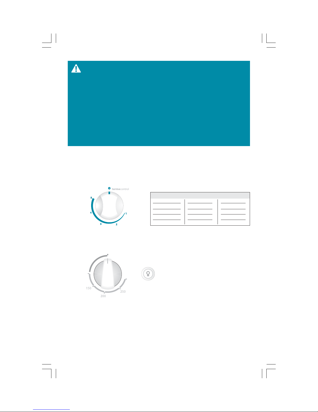
Perilla de horno con termocontrol.
(Aplica para los modelos L1700, PREM700, EM800 y EM1700)
La perilla de control del horno está localizada en el panel de control, tiene 5 posiciones y
su tabla de equivalencias en temperaturas se muestra en la siguiente tabla.
En condiciones óptimas éstas son temperaturas aproximadas:
Posición perilla Gas L.P. Gas Natural
1
2
3
4
5
140 ºC - 150 ºC
190 ºC - 200 ºC
210 ºC - 230 ºC
260 ºC - 270 ºC
280 ºC - 290 ºC
164 ºC
182 ºC
213 ºC
245 ºC
301 ºC
Perilla de horno con termostato.
(Aplica para los modelos L1700T, 1700T, J1700T, JL1700T, JEM1748, JEM1758, DL1750T,
EM1765, EM1770, EM1771, JEM1770 y EM1758)
°C/oven
broil
La perilla del horno con termostato, indica las temperaturas en el panel de control.
Luz de horno
En los modelos: JEM1758 y EM1765 para encender la luz del horno presione el botón con el
indicador en forma de foco.
Para los modelos EM1770, EM1771 y JEM1770 presione el botón marcado con la palabra
"luz" localizado en el copete de la estufa.
Nota:
Lea la sección de Recomendaciones de cocinado, para hornear mejor sus alimentos.
14
Page 15

Para encender el horno con termocontrol o con termostato
1 Abra la puerta del horno.
2 Inmediatamente después, acerque la flama a la mirilla lo más próximo al quemador.
3 Gire la perilla hasta la temperatura deseada.
4 Espere a que encienda antes de retirar el cerillo y verifique que la flama sea azul por el ori-
ficio central del piso del horno.
5 En caso de que no encienda, regrese al paso 2 y repita las operaciones.
Para encender el horno con botón
1 Verifique que esté conectada a la corriente eléctrica, y que la perilla esté en la posición de
apagado.
2 Abra la puerta del horno.
3 Presione el botón de la chispa y manténgalo así.
4 Empuje la perilla del horno y gírela hasta la máxima posición en el panel de control.
5 Verifique que el quemador efectivamente haya encendido. Y entonces suelte el botón.
6 Visualice la flama por el orificio central del piso del horno.
7 Ajuste la temperatura, girando la perilla a la posición deseada.
8 En caso de que no encienda, regrese al paso 3. Repita las operaciones.
Notas:
• Posiblemente cuando utilice el horno por primera vez perciba un olor "extraño". Este olor
es normal las primeras veces.
• Mientras su horno se calienta, la temperatura en el interior cambia y como consecuencia
pueden formarse gotas de agua en el vidrio de la puerta, esto es normal.
• Para prevenirlo, abra la puerta el primer minuto de calentamiento para dejar salir al aire
húmedo.
3.5 Asador Bajo
(Esta característica aplica para los modelos JEM1748, JEM1758, EM1765, EM1770, EM1771 y
JEM1770).
Para operar el Asador bajo en los modelos de termocontrol, gire la perilla del horno a la posición marcada con el número 5 y espere a que la temperatura sea la adecuada para asar sus
alimentos.
El uso del Asador bajo en los modelos de termostato, es de la siguiente manera. Para encender el Asador, siga los Pasos 1 y 2 del encendido del quemador u horno. Una vez encendido,
gire la perilla del horno hasta la posición “Broil”; espere a que la temperatura sea la adecuada para asar sus alimentos.
Nota: Lea la sección de Recomendaciones de cocinado, en la sección de Posiciones de alimentos en el Asador.
3.6 Reloj
El reloj de la estufa mostrará en la pantalla la leyenda "12:00 " y el indicador luminoso de la
palabra "reloj" permanece encendido, hasta el momento en que usted presione algún botón.
Para ajustar la hora del día, deberá presionar el botón "+" para incrementar el valor de los
minutos. Con el botón "-" disminuya el valor de los minutos, al reducir este valor a cero cambia el dígito de la hora, al valor inmediato inferior.
15
Page 16

4. Mantenimiento
4.1 Guía de limpieza y cuidado
El cuidado y limpieza de su estufa son importantes para que ésta le proporcione un servicio
eficiente y satisfactorio.
SI SU ESTUFA TIENE ENCENDIDO ELECTRÓNICO, DESCONÉCTELA
DE LA CORRIENTE ELÉCTRICA ANTES DE LIMPIAR CUALQUIERA
DE SUS PARTES. NO USE SOSA CÁUSTICA O ALGÚN PRODUCTO
QUE LA CONTENGA YA QUE ÉSTE PUEDE DAÑAR SERIAMENTE
EL ACABADO.
Acabado Exterior
Es necesario mantener su equipo siempre limpio, por lo general bastará con utilizar agua, jabón neutro y un trapo húmedo, enjuagándolo frecuentemente en agua limpia para evitar residuos de jabón.
Algunas partes requerirán un procedimiento diferente.
Capelo
Lave el capelo con agua jabonosa, enjuague y retire el excedente con un trapo húmedo. Para
mejores resultados después de la limpieza aplique limpiador liquido de vidrios, con un trapo
húmedo y espárzalo sobre la superficie. Retire el excedente con un trapo seco.
Panel de control y cubierta porcelanizada
Nunca use limpiadores abrasivos, líquidos limpiadores fuertes o fibras. Las
frutas, azúcares o alimentos de alto contenido ácido pueden causar marcas
y/o manchas en la superficie porcelanizada.
Limpie el panel de control y la cubierta después de cualquier derrame y después de usar el
horno.
Espere a que la superficie se haya enfriado.
Aplique agua y jabón suave.
Enjuague con agua limpia y pula con un trapo seco y limpio.
Para una mejor limpieza, es recomendable usar vinagre de caña y agua tibia. Mezcle al 50%
vinagre blanco de alcohol de caña con 50% de agua tibia y use esta solución con una fibra
suave para remover los restos de comida y manchas en general.
16
Page 17

Panel de control y Cubierta inoxidable
Para eliminar el amarillamiento y evitar que en el futuro se ponga amarillo el panel de control y la cubierta de acero inoxidable, se recomienda usar el Cerama Brite stainlees steel , el
cual viene incluido en la estufa. Siga las instrucciones de aplicación del envase.
Perillas
Las perillas se pueden retirar para facilitar su limpieza.
1 Cerciórese de que la perilla esté fría y jálela hacia afuera.
2 Use agua y jabón suave.
3 Escurra y seque antes de colocarlas nuevamente.
Notas:
• Nunca lave sus perillas cuando estén calientes.
• Evite el uso de fibras abrasivas en su lugar use fibras plásticas.
• Nunca deje remojando las perillas en agua.
Parrillas superiores
Las parrillas se deben lavar regularmente y, por supuesto, después de derrames; espere a que
la temperatura disminuya. Lávelas con jabón y agua caliente, enjuáguelas con agua limpia,
séquelas con un trapo, no las coloque mojadas en la estufa. Para quitarles residuos de comida
quemada, remójelas en una solución de agua con algún limpiador líquido suave. Utilice jabón líquido sin abrasivos.
Quemadores superiores
Los orificios en los quemadores de su estufa deben mantenerse limpios para tener un buen
encendido y una flama pareja. Límpielos periódicamente y especialmente después de derrames, los cuales pueden obstruir dichos orificios.
Para limpiar de manera eficiente los quemadores de su estufa, sólo necesita agua y jabón, tállelos usando una fibra plástica. Los productos de limpieza que contengan sosa cáustica (hidróxido de sodio) mancharán sus quemadores por lo que recomendamos no usarlos.
En caso de que se manchen los quemadores. Le recomendamos seguir los siguientes pasos y
retirar la tapa porcelanizada:
1 Vierta una cantidad generosa de vinagre blanco de alcohol de caña en un recipiente e in-
troduzca los quemadores con la cara hacia abajo, en contacto directo con el vinagre.
2 Deje reposar por espacio de ocho horas.
3 Enjuague y lave los quemadores con agua, jabón (en polvo o líquido) y fibra de plástico.
4 Seque perfectamente y cerciórese de que no queden residuos de agua.
5 Instale los quemadores nuevamente.
17
Page 18

Puerta de horno
NUNCA SUMERJA LA PUERTA EN AGUA
Lave la puerta con agua jabonosa, enjuague y retire con un trapo húmedo el excedente.
Para mejores resultados después de la limpieza aplique limpiador liquido de vidrios con un
trapo húmedo y espárzalo sobre la superficie. Retire el excedente con un trapo seco.
Para manchas difíciles use una solución de vinagre y agua.
Horno de limpieza continua
El interior del horno está terminado con un recubrimiento especial que no puede limpiarse
de la manera usual con jabón, detergentes, fibras, limpiadores de horno comerciales, cepillos,
entre otros.
El uso de tales limpiadores o de spray para el horno le causarán un daño permanente. Este
recubrimiento especial es un material cerámico poroso de color oscuro, se siente ligeramente
áspero al tacto y funciona de la siguiente manera: Cuando la grasa salpica, el acabado poroso
dispersa la mancha y la absorbe parcialmente.
Esta dispersión incrementa la exposición del cochambre al aire caliente del horno y lo hace
menos notorio.
El cochambre no desaparece completamente y algún tiempo después de uso continuo, las
manchas pueden desaparecer.
Para limpiar el horno de limpieza continua:
1 Deje enfriar la estufa antes de empezar. Recomendamos usar guantes de hule.
2 Retire las parrillas y trastes.
3 El cochambre visible puede reducirse al encender el horno a 200 °C, cierre la puerta y gire
la perilla de control del horno hasta alcanzar la temperatura deseada, tenga así el horno
por lo menos 4 horas. La repetición cíclica será necesaria antes de mejorar su apariencia.
4 Si un derrame o mancha fuerte ocurre en la superficie porosa, tan pronto como el horno se
enfríe, quite lo más que pueda usando un poco de agua y un cepillo de nylon de cerdas du-
ras. Use agua con moderación y cámbiela frecuentemente, manteniéndola tan limpia como
sea posible, vaya secando con un trapo, toalla de papel o esponja.
No talle, ya que podrían quedar pelusas en el recubrimiento del horno, si el agua dejara un
rastro blanco en el acabado al secarse, repita la operación y seque con un trapo limpio, empezando por la orilla de la mancha y terminando en el centro.
Este recubrimiento especial trabaja mejor en pequeñas salpicaduras. Las parrillas del horno y
el revestimiento de la puerta no están tratados con este recubrimiento.
18
Page 19

NO RASPE LA SUPERFICIE CON CUCHILLO, PODRÍA DAÑAR PERMANENTE EL ACABADO.
Parrillas del horno
Las parrillas se pueden limpiar con un limpiador abrasivo suave, siguiendo las instrucciones
del fabricante. Después de lavarlas, enjuáguelas y séquelas con un trapo limpio.
Para quitar las manchas difíciles, puede usar fibra o cepillos de cerdas firmes.
Interior de la puerta y piso de horno
En condiciones normales de limpieza, use solamente agua jabonosa, si hay derrames o salpicaduras muy fuertes puede recurrir a limpiadores abrasivos suaves, también puede usar fibras. No permita que los derrames o salpicaduras de comida con alto contenido de azúcar o
ácido (como leche, jitomates, salsas, jugos de frutas o relleno de pay) se queden en la superficie por mucho tiempo.
5. Recomendaciones de Cocinado
5.1 Temperaturas del Horno
Le recomendamos tomar la siguiente como una guía para hornear mejor sus alimentos.
Temperatura del horno Función/Alimento
ºC ºF
140 - 150
190 - 200
210 - 230
260 - 270
280 - 290
284 - 302
374 - 392
410 - 446
500 - 518
536 - 554
Pasteles, postres
Pasteles, galletas, panes, carnes, pescado
Tartas, pizzas
Precalentar 10 - 15 minutos
Asar
5.2 Posiciones de Alimentos en el Horno
Notas:
• Las posiciones de la parrilla se nombran de abajo hacia arriba A, B, C, D y E.
• La mayoría de los alimentos se hornean bien en el centro del horno (Posición de la Parrilla
C).
• Los alimentos de mayor volumen se hornean bien en la parte media/baja del horno (Posi-
ción de la parrilla B).
• No se recomienda utilizar la Posición de la parrilla A.
Alimento Posición parrilla Tiempo
Galletas
Pasteles
Tartas
Pan
Pastas
Carnes y pescados (pequeños)
Carnes, piezas grandes como
pavo o pierna de cerdo
D,C
C, B
C
C
C
C
B
Los indicados en la receta
19
Page 20

5.3 Posiciones de Alimentos en el Asador
Notas:
• Las posiciones de la parrilla se nombran de abajo hacia arriba A, B y C.
• Para dorar/asar alimentos con grosor menor a 2,0 cm utilizar la posición de la parrilla B o C.
Ejemplos: Pan tostado, hamburguesas, arrachera.
• Para dorar/asar alimentos con grosor mayor a 2,0 cm utilizar la posición de la parrilla A.
Ejemplos: Pechugas de pollo enteras, T- Bone steak 1,5” .
• Los alimentos de mayor grosor deben colocar se en la posición más alejada del quemador
para evitar que se doren demasiado.
Asador bajo Posición parrilla Tiempo
Pan tostado
Hamburguesas
Pechugas de pollo
C
B
A
El indicado en la receta
5.4 Recomendaciones generales
Cuando cocine, tome en cuenta las siguientes recomendaciones:
1. Cuando accione una perilla, revise que el quemador correspondiente haya encendido.
2. Fíjese en la flama, no en la perilla mientras reduce la flama del quemador.
3. Voltee las asas de los utensilios de cocina hacia un lado o hacia atrás para que no queden
sobresaliendo de la estufa.
4. Use utensilios del tamaño apropiado. Evite el uso de cacerolas inestables o fáciles de vol-
tear.
5. Si va a cocinar con trastes de vidrio, éstos deberán ser refractarios.
6. No utilice recipientes que tengan un anillo metálico como base (Wok), este anillo puede
actuar como una trampa de calentamiento, provocando daños en la parrilla y el quemador. En consecuencia puede aumentar el nivel de monóxido de carbono, constituyendo un
riesgo para la salud.
7. Mientras cocine en la estufa, no use ropa suelta o accesorios de vestir colgantes.
8. Tenga cuidado al alcanzar artículos almacenados en gabinetes arriba de la estufa.
9. Los alimentos a freír deben estar lo más secos posible.
10. Siempre caliente despacio la grasa y vigile durante el calentamiento.
11. Cuando vaya a flamear algún platillo en la estufa, apague el ventilador de la campana
extractora. Si la estufa está localizada cerca de una ventana, no use cortinas largas.
12. Siempre apague los quemadores antes de quitar los utensilios de la estufa.
13. Aleje cualquier artículo plástico de los quemadores. Los materiales pueden encenderse al
estar en contacto con las flamas o superficies calientes del horno y pueden causar quemaduras.
14. Nunca use agua para apagar aceite que se haya incendiado, ni tampoco levante una cace-
rola que está flameando, cúbrala completamente con una tapadera que selle bien, también puede hacerlo con una hoja de lámina, molde, etc.
15. Cuando abra la puerta del horno caliente, permanezca alejada de la estufa, el aire calien-
te y vapor que salen suelen causar quemaduras en manos, cara y ojos.
16. Al usar bolsas de cocinado o rostizado (empaques especiales con que vienen ciertos ali-
mentos) en el horno, siga las instrucciones del fabricante.
17. Si tuviera un incendio por la grasa en la charola del asador y/o gratinador, apague el que-
mador del horno y mantenga cerrado el compartimiento del asador hasta que el fuego se
extinga por sí solo.
18. Nunca caliente en el horno comida en recipientes sin abrir, la presión puede subir y hacer
estallar el recipiente causando un accidente.
19. Nunca deje que la flama de un quemador sobresalga de las orillas del traste de cocina.
20. Si llegará a producirse fuego en el interior del horno, apague inmediatamente el quema-
dor del horno o asador, según sea el caso, y mantenga la puerta cerrada hasta el fuego se
extinga por sí solo.
20
Page 21

6. Diagramas eléctricos
Diagrama eléctrico
Aplica para los modelos JEM1758 y EM1758
Diagrama eléctrico
Aplica para los modelos EM1765
ADVERTENCIA:
Desconecte este aparato de la
energía eléctrica antes de efectuarle
cualquier tipo de servicio
Para obtener la
clasificación eléctrica
L-1 N
refiérase a la placa de
identificación
A1
Rojo/Red
Rojo/Red
Rojo/Red
Interruptor bujía/
Spark plug switch
Interruptor luz horno/
Oven light switch
WARNING:
Unplug this appliance from electric
power before performing any type
of service
To obtain electrical
rating refer to
identification plate
Rojo/Red
Rojo/Red
Rojo/Red
Rojo/Red
Rojo/Red
Luz horno/Oven light
Naranja/
Orange
110 V 50 Hz 0,5 A
ADVERTENCIA:
Desconecte este aparato de la
energía eléctrica antes de efectuarle
cualquier tipo de servicio
Para obtener la
clasificación eléctrica
refiérase a la placa de
identificación
Rojo/Red
Rojo/
Red
Interruptor luz horno/
Oven light switch
Rojo/Red
127 V 60 Hz 0,5 A
Interruptor bujía/
Spark plug switch
WARNING:
Unplug this appliance from electric
power before performing any type
of service
To obtain electrical
rating refer to
identification plate
Violet/Violet
Rojo/Red
Rojo/Red
Rojo/Red
Rojo/Red
Rojo/Red
Blanco/White
Luz horno/
Naranja/Orange
Oven light
Violeta/Violet
Módulo
ignición/
Ignition
module
Blanco/White
Módulo
ignición/
Ignition
module
N
Blanco/White
183D9627P011
Blanco/White
L
N
183D9602P006
NL-1
Blanco/White
L
Diagrama eléctrico
Aplica para el modelo JEM1770XO
ADVERTENCIA:
Desconecte este aparato de la
energía eléctrica antes de efectuar
cualquier tipo de servicio
N L-1
White/Blanco
clasificación eléctrica
refiérase a la placa de
Right Front/
Frente Der.
White/Blanco
Oven light/
Luz horno
Para obtener la
identificación
Right Rear/
Trasero Der.
To obtain electrical
identification plate
Thermostat/
Central
Termostato
Orange/Naranja
rating refer to
Red/Rojo
Red/Rojo
Red/Rojo
Red/Rojo
Red/Rojo
White/Blanco
110 V 50 Hz 0,5 A
WARNING:
Unplug this appliance from electric
power before performing any type
of service
A1
Black/Negro
Left Rear/
Left Front/
Trasero Izq.
Frontal Izq.
Black/Negro
N
Violet/Violeta
L
Ignition Module/
Módulo ignición
Oven light switch/
Interruptor luz horno
Red/Rojo
A2
183D9627P020
Red/Rojo
21
Page 22

Diagrama eléctrico
Aplica para los modelos EM1770
ADVERTENCIA:
Desconecte este aparato de la
energía eléctrica antes de efectuarle
cualquier tipo de servicio
Para obtener la
clasificación eléctrica
N
refiérase a la placa de
identificación
Fron Der.
Front R.
Blanco/White
Blanco/White
B2
Blanco/White
Naranja/Orange
Lámpara piloto/
Pilot lamp
127 V 60 Hz 0,5 A
Diagrama eléctrico
Aplica para los modelos EM1771
ADVERTENCIA:
Desconecte este aparato de la
energía eléctrica antes de efectuarle
cualquier tipo de servicio
Para obtener la
clasificación eléctrica
N
refiérase a la placa de
identificación
Fron Der.
Front R.
Blanco/White
Blanco/White
B2
Blanco/White
Naranja/Orange
Lámpara piloto/
Pilot lamp
110 V 50 Hz 0,5 A
WARNING:
Unplug this appliance from electric
power before performing any type
of service
To obtain electrical
rating refer to
identification plate
Capacitor
Tras Der.
Tras. Izq./
Central
Rear R.
Rear L.
Rojo/Red
Rojo/Red
Rojo/Red
Módulo
Rojo/Red
ignición/
Ignition
Rojo/Red
module
Timer digital/
Digital Timer
Blanco/White
Naranja/Orange
B3
Front. Izq./
Front L.
Front. Izq./
Front L.
Chasis/
Chassis
Negro/Black
N
Violeta/Violet
L
Rojo/Red
12345
Chasis/
Chassis
Negro/Black
N
Violeta/Violet
L
Rojo/Red
12345
Toroide/Toroid
L-1
A1
Rojo/RedNegro/Black
Rojo/Red
A2
B1
183D9602P013
Toroide/Toroid
L-1
A1
Rojo/RedNegro/Black
Rojo/Red
A2
B1
183D9602P018
Diagrama eléctrico
Aplica para los modelos JEM1770
ADVERTENCIA:
Desconecte este aparato de la
energía eléctrica antes de efectuarle
cualquier tipo de servicio
Para obtener la
clasificación eléctrica
refiérase a la placa de
N
identificación
Blanco/White
Blanco/White
110 V 50 Hz 1 A
Blanco/
White
Lámpara pilotos/
Pilot lamp
Fron. der./
Front R.
B1
Naranja/Orange
Capacitor
Tras. der./
Rear R.
22
WARNING:
Unplug this appliance from electric
power before performing any type
of service
To obtain electrical
rating refer to
identification plate
Central/
Tras. izq./
Fron. izq./
Center
Rear L.
Rojo/Red
Rojo/Red
Rojo/Red
Rojo/Red
Módulo
Timer digital/
Digital Timer
Blanco/White
B2
Naranja/Orange
ignición/
Ignition
module
Blanco/White
Toroide/
Front L.
12345
Toroid
Chasis/Chassis
Negro/Black
Negro/Black
N
Violeta
L
Rojo/Red
L-1
Rojo/
A1
Red
A2
B3
183D9602P012
Page 23

7. Problemas y soluciones
Antes de llamar al servicio
Problema Causa posible Solución
El horno no funciona o no enciende
Los quemadores
no encienden o
prenden
El reloj no funcio-naSu estufa no está conectada a la
La luz de horno no
enciende o no funciona
Fuerte olor al usar
el horno
Se terminó el gas de su casa Verifique si otros aparatos domésticos que em-
Su estufa no está conectada a la
corriente eléctrica (segun modelo)
La perilla no esta en la posición correcta
Se terminó el gas de su casa.
Su estufa no está conectada a la
corriente eléctrica.
La perilla no está en la posición correcta.
Los orificios de los quemadores
pueden estar obstruidos.
El quemador puede estar mal colocado.
Los quemadores están mojados.
corriente eléctrica.
Hubo un corte en el suministro de
energía eléctrica y esta se ha restablecido (el reloj marcar· (12:00 parpadeando).
Su estufa no está conectada a la
corriente eléctrica.
El foco puede estar flojo.
El foco puede estar fundido.
Primeras ocasiones de uso del horno.
pleen gas funcionan correctamente, de no ser así
llame a su proveedor de gas.
Asegúrese de que su estufa esté conectada correctamente a la corriente eléctrica y que el suministro de energía eléctrica sea regular.
Lea cuidadosamente la sección de Encendido del
Horno en su manual de uso y cuidado.
Verifique si otros aparatos domésticos que empleen gas funcionan correctamente, de no ser así
llame a su proveedor de gas.
Asegúrese de que su estufa esté conectada correctamente a la corriente eléctrica y que el suministro de energía eléctrica sea regular.
Lea cuidadosamente la sección de "Encendido de
Quemadores" en su manual de uso y cuidado.
Retire los quemadores y limpie los orificios con
un cepillo dental, teniendo cuidado de no hacer
más grandes dichos orificios.
Verifique la posición correcta del quemador conforme al diagrama.
Deje que los quemadores estén secos completamente o séquelos usted mismo, posteriormente
intente nuevamente encenderlos.
Asegúrese de que su estufa esté conectada correctamente a la corriente eléctrica y que el suministro de energía eléctrica sea regular.
Lea cuidadosamente la sección "Reloj Digital en
Copete" en su Manual de uso y cuidados. En caso
de tener su estufa Quemador Programable refiérase a la sección de "Quemador Programable".
Asegúrese de que su estufa esté conectada correctamente a la corriente eléctrica y que el suministro de energía eléctrica sea regular.
Apriete el foco girándolo en el mismo sentido de
las manecillas del reloj.
Debe cambiar el foco por un foco similar de 40
Watts.
Es normal que las primeras ocasiones que se usa
el horno, éste despida un olor extraño. NO es un
problema, este olor ira desapareciendo con el
uso.
23
Page 24

8. Características por modelo
L1700BBEModelo
Copete o capelo Copete
Encendido quemadores sup.
Control horno
Acabado de horno
Encendido horno
Luz horno
Copete o capelo Copete
Encendido quemadores sup.
Control horno
Acabado de horno
Encendido horno
Luz horno
Cerillo
Termocontrol de
5 posiciones
Limpieza
continua
Manual
1700TBBEModelo
Cerillo
Termostato sin
seguridad
Limpieza
continua
Manual
L1700LLE
Copete
Cerillo
Termocontrol de
5 posiciones
Limpieza
continua
Manual
1700TLE
Copete
Cerillo
Termostato sin
seguridad
Limpieza
continua
Manual
L1700TBBE
Copete
Cerillo
Termostato sin
seguridad
Limpieza
continua
Manual
1700TLLE
Copete
Cerillo
Termostato sin
seguridad
Limpieza
continua
Manual
1700TBE
Copete
Cerillo
Termostato sin
seguridad
Limpieza
continua
Manual
J1700TBE
Copete
Cerillo
Termostato con
seguridad
Limpieza
continua
Manual
JL1700TBBEModelo
Copete o capelo Copete
Encendido quemadores sup.
Control horno
Acabado de horno
Encendido horno
Luz horno
Cerillo
Termostato con
seguridad
Limpieza
continua
Manual
24
PREM700BBE
Copete
Cerillo
Termocontrol de
5 posiciones
Limpieza
continua
Manual
PREM700LLE
Copete
Cerillo
Termocontrol de
5 posiciones
Limpieza
continua
Manual
EM1765
Copete
Electrónico botón
Termostato sin
seguridad
Limpieza
continua
Bujía
Si
Page 25

JEM1748BBEModelo
Copete o capelo Copete
JEM1758BE
Copete
EM800CBCE
Capelo
EM800CNCE
Capelo
Encendido quemadores sup.
Control horno
Acabado de horno
Encendido horno
Luz horno
Copete o capelo Copete
Encendido quemadores sup.
Control horno
Acabado de horno
Encendido horno
Luz horno
Copete o capelo Copete
Encendido quemadores sup.
Control horno
Acabado de horno
Encendido horno
Cerillo
Termostato con
seguridad
Limpieza
continua
Manual
EM1770BBEModelo
Electrónico
integrado
Termostato sin
seguridad
Limpieza
continua
Manual
Si Si Si
EM1700BEModelo
Cerillo
Termocontrol 5
posiciones
Limpieza
continua
Manual
Electrónico botón
Termostato con
seguridad
Limpieza
continua
Manual
Si
JEM1770BBE
Copete
Electrónico
integrado
Termostato con
seguridad
Limpieza
continua
Manual
EM1758BBE
Copete
Electrónico botón
Termostato sin
seguridad
Limpieza
continua
Manual
Cerillo
Termocontrol 5
posiciones
Limpieza
continua
Manual
EM1770NNE
Copete
Electrónico
integrado
Termostato sin
seguridad
Limpieza
continua
Manual
JEM1770XO
Copete
Electrónico
integrado
Termostato con
seguridad
Limpieza
continua
Bujía
Cerillo
Termocontrol 5
posiciones
Limpieza
continua
Manual
DL1750TBBE
Copete
Cerillo
Termostato sin
seguridad
Limpieza
continua
Manual
EM1771BBE
Copete
Electrónico
integrado
Termostato sin
seguridad
Limpieza
continua
Manual
Luz horno
Si Si
Si
25
Page 26

Congratulations!
You have just acquired a product of the highest quality, design and technology.
Since at we’re committed in satisfying the expectative and needs of our customers, we work in order to offer
you the best service with safe and competitive products at an
international level.
endorses your range warranty and takes care of your
after sales requirements through Serviplus, Latin-America’s
leader company in appliance service.
We proudly thank your preference and confidence.
26
Page 27

Contents
1. Features by model
1.1 Parts and accessories ............................................................................ 28
2. Installation instructions
2.1 Space conditions ................................................................................... 29
2.2 Leveling ................................................................................................. 30
2.3 Installing the backguard ...................................................................... 30
2.4 Gas hookup ........................................................................................... 31
2.5 Electric hookup ..................................................................................... 32
2.6 Installing the burners ........................................................................... 33
2.7 Surface grates installation ................................................................... 34
2.8 Oven door ............................................................................................. 34
2.9 Oven shelves installation ..................................................................... 34
3. Operation
3.1 Safety .................................................................................................... 35
3.2 Glass lid ................................................................................................. 36
3.3 Lighting a surface burner .................................................................... 36
3.4 Turning on the oven ............................................................................ 38
3.5 Lower broiler ........................................................................................ 39
3.6 Clock ...................................................................................................... 39
4 Maintenance
4.1 Care and cleaning guide ...................................................................... 40
5 Cooking tips
5.1 Oven temperatures .............................................................................. 43
5.2 Recommended food positions (bake) ................................................. 43
5.3 Recommended food positions (broil) ................................................. 44
5.4 General Recommendations ................................................................. 44
6. Electric diagrams ............................................................... 45
7. Problems and solutions .................................................... 47
8. Features by model ............................................................. 48
27
Page 28

1.1 Parts and accessories
2 Lateral top wire surface grates
1 Central top wire surface grate
1 Porcelain enameled grill
1 or 2 Oven shelves (depending on model).
The following features do not apply to model EM800:
2 Metallic supports for the backguard
4 Black Phillips head bolts
4 Wing nuts
1 Broiler pan (exclusive for models JEM1748, JEM1758, EM1765, EM1770, EM1771 and
JEM1770).
Oven light button
(depending on model)
75,7
cm
Backguard
Surface grates
Cooktop
Ignition button
Control panel
Knobs
Handle
Door
Broiler
28
108,2 cm
90,9 cm
Oven shelves
Page 29
2. Installation instructions
Keep these instructions for future reference.
Make sure your range is installed by qualified personnel or by a SERVIPLUS technician.
2.1 Space conditions
Preparation
1 Remove all adhesives and packing material, including the plastic film that covers some
parts of the range, for example, the stainless steel cooktop. We recommend you to recycle
carton packing material taking it to the special depots made for this specific purpose.
2 Remove accessories from inside the oven.
BEFORE INSTALLING THE RANGE ON A LINOLEUM FLOOR, OR ANY
OTHER SYNTHETIC COVERING, BE SURE THIS MATERIAL AND THE
FURNITURE NEXT TO THE RANGE CAN WITHSTAND A TEMPERATURE OF 95 °C WITHOUT SUFFERING DEFORMATIONS.
NEVER INSTALL YOUR RANGE ON A CARPET OR ANY OTHER FLAMMABLE MATERIAL.
IN ORDER TO REDUCE THE RISK OF FIRE, INSTALL YOUR KITCHEN CABINETS ACCORDING TO THE DIMENSIONAL DIAGRAM, AVOID INSTALLING CABINETS ABOVE
THE RANGE AT A DISTANCE SMALLER THAN THE SPECIFIED.
Location
We suggest NOT to install your range in a place exposed to strong drafts. In the case that
your range is located near a door or window, try to keep them closed while cooking.
Dimensions and clearances
The following drawing shows the minimum clearances required for installation. This dimensions must be observed.
76,2 cm
46 cm min.
76 cm min.
2,5 cm if installed
next to a wall
2 cm for cabinets that do
not exceed counter height
or range front face
91,5 cm
33 cm max.
top cabinet
0,6 cm from
front of side
panel to the
front of cabinet
29
Page 30

2.2 Leveling
We recommend to level the range before performing gas and electric
connections in order to achieve even baking results.
Your range has two leveling bolts located at the rear of the range’s floor. Place the range
on its installation spot.
Place a level over oven’s shelves.
If range is not level, tilt the range on its side -with the help of a second person- and turn
the bolt. Repeat the operation on the other side until achieving the desired height.
2.3 Installing the backguard
Step 1
Unpack backguard located on the back of the range.
Step 2
Place backguard over cooktop and make sure that the holes on both parts match so the backguard is correctly seated (see photograph).
Step 3
Place all 4 Phillips bolts on the top face of the backguard and the bottom face of the cooktop, securely tighten the wing nuts.
photograph 1 photograph 2
Step 4
Place the metallic supports in diagonal position (see photograph 2).
30
Page 31

2.4 Gas Hookup
Make sure your house has a gas pressure regulator that supplies the correct
pressure.
1 Close the main gas shut-off valve before disconnecting your old range and leave it closed
until the hookup is completed.
2 Install a manual shut-off valve, in the main gas supply line, in an accessible place, out of
the range. Make sure all people using the range know how to operate this valve and turn
it off if necessary.
regulator
valve
DO NOT USE PLASTIC HOSE FOR THE GAS INSTALLATION.
3 For the installation of your range use a male termi-
nal connector NPT 9,5 mm (3/8”) at the outlet of
regulator and connect it to a copper pipe with 9,5
mm (3/8”) flare nuts.
4 Connect the shut-off valve and the copper tube us-
ing 9,5 mm (3/8”) bell fittings on the ends. Flexible
copper pipe and/or hose must be 1,20 m to 1,50 m
and must withstand temperatures above 250 °C
5 When you have finished the connections, make sure
all knobs on the control panel are in the OFF setting
and then open the main gas shut-off valve.
6 Use soap and water on all fittings and connections
to make sure there are no leaks.
9,5 mm (3/8”)
bell fittings
9,5 mm (3/8”)
flare nuts
THIS APPLIANCE CAN BE USED WITH LP OR NATURAL GAS, IT
WAS FACTORY SET FOR LP GAS. IT IS DESIGNED TO RUN AT A
PRESSURE OF 2,75 kPa (11 inches of water column) IN CASE IT
MUST BE CONNECTED TO NATURAL GAS, IT MUST HAVE A
PRESSURE OF 1,76 kPa (7 inches of water column).
Copper pipe
31
Page 32

FOR THIS LAST CASE, A SERVIPLUS TECHNICIAN SHOULD PERFORM THE CONVERSION BEFORE
YOU CAN USE YOUR RANGE, WITHOUT A CHARGE (VALID ONLY DURING THE FIRST YEAR
FROM THE DATE OF PURCHASE).
TO PREVENT GAS LEAKS USE NEW FITTINGS, APPLY A JOINT SEALER OR SPECIAL TAPE IN AL
EXTERNAL CONNECTIONS.
DO NOT USE AN OPEN FLAME TO FIND GAS LEAKS.
WHEN MOVING THE RANGE AVOID CRUSHING THE GAS CONNECTION TO PREVENT GAS
LEAKS.
BE SURE TO MAINTAIN THE VICINITY OF THE RANGE FREE OF
COMBUSTIBLE MATERIALS, GASOLINE AND OTHER FLAMMABLE
VAPORS AND LIQUIDS.
2.5 Electric Hookup
This appliance is designed to run on a nominal voltage of 127 V~ 60 Hz or
110 V ~ 50 Hz (Depending on model. Refer to electric diagrams).
Check you have a proper receptacle installed on the wall and grounded, checked by a qualified electrician.
If your range has an oven light, before using it make sure the receptacle is properly
grounded and protected by a 15-20 A breaker or fuse
Try not to plug in any other appliance to the same wall receptacle. The electric cord should
not be twisted and avoid any contact with the rear of the range. In case you need an extension cord, you must use a cord having the same features of the original electric cord.
Never cut or remove the plug’s grounding pin.
CORRECT INCORRECT
32
Page 33

2.6 Installing the burners
Make sure the burner and the cap are correctly installed according with the
figure. Porcelain-enamel caps seat over the aluminum body.
Porcelain enamel caps should be installed over aluminum body.
Porcelain
enamel cap
Aluminum body
Mixture tube
Triple Ring burners
(See "Features by model" chart)
Your range is equipped with a new burner, which is recommended to cook on large cook-
ware and to obtain even cooking results. The following considerations must be taken into account in order to get a proper operation of this burner.
Before turning on this burner make sure both caps are properly seated in their place. The
enameled portion of the caps must be placed upwards. Be careful not to hit and/or push the
spark plug since triple ring spark plugs are taller than the rest.
Keep burner free of any grease, and avoid to leave cleaner residues on the spud which is located on the base, since it may cause the burner to clog, resulting in an improper operation.
INCORRECTCORRECT
Burners' caps
Burner base
33
Page 34

2.7 Surface grates installation
A
B
C
D
E
Every time you need to remove surface grates for cleaning, make sure you place them back
in their original position (see figure).
2.8 Oven door
The oven door is removable, so the interior of the range becomes more accessible. To remove
the door, fully open it. With both hands slide hinge hooks forward and make sure they are
completely fixed by lightly raising the door.
Raise the door with both hands until realizing how easy it goes out, then pull up.
To replace it, center the arms of the hinges into the bottom slots of the metallic frame and
slide the hooks backward in order to fix the mechanism.
BE CAREFUL NOT TO PLACE YOUR HANDS BETWEEN HINGES AND OVEN’S FRAME AS THE
ARMS COULD VIOLENTLY SNAP BACK PINCH-
Sliding hook
Hinge
ING YOUR FINGERS.
2.9 Oven shelves installation
Oven shelves are designed with a stop lock that prevents them from tilting and coming completely out. This is specially convenient when you take the food in and out of the oven.
To remove oven shelves, slide them towards you, lift up the front and pull out. To replace
them, place the shelf on the support (curved portion of the shelf must face oven’s rear wall
and must be under the stop lock), tilt the front up and push inside the oven cavity until the
shelf passes the stop lock on the oven wall. Next lower the front portion and slide the shelf
as far as it will go.
Shelves can be placed at 5 heights as shown in the
figure. The Cooking Tips section specifies the recommended use for each shelf position.
34
rear
wall
Page 35

3. Operation
3.1 Safety
For your own safety follow these recommendations:
IF YOU SMELL GAS:
1) OPEN ALL WINDOWS
2) DO NOT TOUCH ANY ELECTRICAL SWITCH
3) EXTINGUISH ALL FLAMES BY SHUTTING OFF THE MAIN
VALVE.
4) IMMEDIATELY CALL YOUR GAS SUPPLIER.
NEVER USE YOUR RANGE TO WARM UP A ROOM, IT IS VERY DANGEROUS.
DO NOT OBSTRUCT OVEN AND BROILER COMBUSTION GASES OUTLET
• Do not let children alone or without supervision when the range is hot or in operation.
They could result with serious burns.
• Do not let anyone to climb, stand or hang from the oven’s door or the top of the range.
• Do not let grease or other flammable materials to accumulate in or near the range.
• Gas appliances can cause an exposure to some toxic and/or harmful substances caused primarily by the incomplete combustion of natural as or LP fuels, mainly benzene formaldehydes and soot.
AN INADEQUATE INSTALLATION, SETTING, ALTERATION OR MAINTENANCE CAN CAUSE DAMAGE AND ACCIDENTS.
A PROPERLY ADJUSTED BURNER IS THE ONE THAT EXHIBITS A
BLUISH FLAME RATHER THAN A YELLOWISH ONE.
FOR YOUR SAFETY DO NOT STORE GASOLINE OR OTHER FLAMMABLE LIQUIDS IN THE VICINITY OR INTERIOR OF THIS RANGE.
DO NOT USE OVEN FOR A STORAGE AREA, ITEMS STORED IN IT
CAN IGNITE.
DO NOT TRY TO REPAIR OR REPLACE ANY PART OF YOUR
RANGE, UNLESS SPECIFIED IN THIS MANUAL.
35
Page 36

3.2 Glass lid
(Applies to model EM800)
Before using your range, make sure control knobs are in the OFF position.
Raise the glass lid, it will remain in a vertical position, you do not have to hold it.
The glass lid is not designed to cook over it.
Hinges are carefully calculated in order to decrease the risk of having the crystal plate fall
and break, as they will soften the impact that it would receive when hitting the cooktop, in
case it accidentally slips off. However use extreme caution when raising and lowering it as it
is a fragile part.
WHEN USING SURFACE BURNERS AND/OR OVEN ALWAYS RAISE THE GLASS
LID.
3.3 Lighting a surface burner
BEFORE LIGHTING THE BURNERS REMOVE ALL PACKING MATERIAL THAT PROTECT THE RANGE.
OPERATION OF ALL BURNERS AND OVEN MUST BE CHECKED
AFTER THE RANGE AND GAS CONNECTIONS HAVE BEEN PROPERLY VERIFIED AGAINST LEAKS.
WHEN THE BURNER LIGHTS FOR THE FIRST TIME, FLAME WILL
BE ALMOST HORIZONTAL AND WILL LIGHTLY RAISE ABOVE THE
BURNER, IN ADDITION YOU WILL HEAR A HISSING SOUND FOR
30 TO 60 SECONDS.
36
AS YOU DECREASE THE BURNER FLAME, LOOK AT THE FLAME,
NOT THE KNOB.
CORRECTINCORRECT
Blue tipsYellow tips
Page 37

HIGH
LOW
Match ignition ranges
(Applies to models L1700, L1700T, 1700T, J1700T, JL1700T, PREM700, JEM1748, DL1750T,
EM800 and EM1700)
1 Make sure control knobs are in the OFF position.
2 Light a match.
3 Push and turn the knob that controls the burner you want to use towards the HIGH po-
sition.
4 Carefully approach the lighted match to the burner.
Button electronic ignition ranges
(Applies to models JEM1758, EM17655 and EM1758)
When pushing the button or turning the knob, ignitors will automatically spark
on all burners. This is normal.
1 Make sure knobs are in the off position, if equipped with mechanism knobs, they should
be in the “out” position. Make sure range is plugged in to electric power.
2 Press and hold the electronic ignition button, marked
with a thunder icon, you will hear the characteristic
sound of the burner’s electric ignitor.
3 Press the knob that corresponds to the burner you want
to use and turn it to HIGH setting, the burner will light
within few seconds. Once lit, release the button and
regulate the flame size turning the knob.
Built-in electronic ignition
(Applies to models EM1770, EM1771 and JEM1770)
Just make sure to plug the power cord into a properly grounded receptacle.
1 Push the knob in and turn it counterclockwise to the setting marked with the icon or
"HIGH" setting.
2 You will hear the characteristic sound of the burner’s electric ignitor.
3 Once the burner is lit, turn the knob so you can adjust the flame to the desired size.
When operating the knob, all ignitors will spark, this is normal. This sound is normal and is
caused by the air-gas mixture inside the burner.
IN THE EVENT OF A POWER OUTAGE, YOU CAN LIGHT SURFACE BURNERS BY APPROACHING A LIT MATCH TO THE
BURNER, THEN CAREFULLY TURN THE KNOB TO THE “HIGH/ ”
SETTING. BE CAREFUL WHEN TURNING ON THE BURNERS THIS
WAY.
BURNERS THAT WERE LIT AT THE MOMENT OF THE POWER
OUTAGE WILL STAY OPERATING NORMALLY UNTIL THEY ARE
TURNED OFF.
37
Page 38

TO ENSURE A CORRECT OPERATION OF THE GRILL, IT MUST BE
RUN AT LOW FLAME.
IF THE LEVEL OF YOUR GAS TANK IS LOW, THEN THE YELLOW
FLAMES ARE A SIGN OF THIS CONDITION.
IF AFTER PERFORMING THE AIR SHUTTER ADJUSTMENT THE
YELLOW FLAMES WON’T DISAPPEAR, FIND THE TELEPHONE
NUMBER OF SERVIPLUS ON THE LAST PAGES OF THIS MANUAL,
THEY WILL PERFORM THE APPROPRIATE ADJUSTMENTS.
3.4 Turning on the oven
Oven control knob equipped with thermocontrol
(Applies to models L1700, PREM700 EM800 and EM1700)
Oven control knob is located in the control panel. It has 5 positions and the following table
shows the equivalent temperature of each position:
At optimum conditions, these temperatures are approximate.
Knob setting LP Gas Natural Gas
1
2
3
4
5
140 ºC - 150 ºC
190 ºC - 200 ºC
210 ºC - 230 ºC
260 ºC - 270 ºC
280 ºC - 290 ºC
164 ºC
182 ºC
213 ºC
245 ºC
301 ºC
Oven control knob equipped with thermostat
(Applies to models L1700T, 1700T, J1700T, JL1700T, JEM1748, JEM1758, DL1750T, EM1765,
EM1770, EM1771, JEM1770 and EM1758)
°C/oven
Oven control knob equipped with thermostat shows temperatures at the control panel.
broil
Oven Light
In models JEM1758 and EM1765 just press the button marked with a light bulb icon.
For models EM1770, EM1771 and JEM1770 press the button marked with the word "light" lo-
cated in the backward of the appliance
Note:
Read the Cooking Tips section, to get better baking results.
38
Page 39

To turn on the thermocontrol or thermostat oven:
1 Open oven door.
2 Approach a flame to the small window as close to the burner as possible.
3 Turn the knob to the desired temperature.
4 Wait until the burner turns on before taking off the match and make sure the flame is blue
taking a look through the center window on the oven’s floor.
5 In case the burner does not light, go back to step 2 and repeat procedure.
To turn on the button oven
1 Make sure the range is plugged to the electric power and the control knob is in the OFF
position.
2 Open oven door.
3 Press and hold the spark-generating button.
4 Press the oven knob and turn it to the maximum setting shown in the control panel.
5 Make sure the burner has lit, then release the button.
6 Take a look of the flame through the central window in the oven’s floor.
7 Adjust temperature by turning the knob to the desired setting.
8 In case the burner does not light, go back to step 3 and repeat procedure.
Notes:
• When using the oven for the first time, you could probably smell an “uncommon” odor.
This odor is normal the first few times you use the oven.
• As your oven heats up, the inside temperature will change and water droplets may form as
a consequence, on the oven’s window. This is normal.
• To prevent it, open the door the first minute of heating so the moist air goes out.
3.5 Lower broiler
(This feature applies to models JEM1748, JEM1758, EM1765, EM1770, EM1771 and JEM1770).
To operate the lower broiler on thermocontrol equipped models, turn the oven control knob
to the position marked “5” and wait until the temperature is the appropriate to broil the
food.
To operate the lower broiler on thermostat equipped models, turn the oven control knob to
the position marked “broil” and wait until the temperature is the appropriate to broil the
food.
Note: Read the Cooking Tips section located in the section Broiler Shelf Positions.
3.6 Clock
The range clock will display "12:00" and the "reloj" (clock) indicator stays lit until the moment you press any button.
To set the time, press the "+" button in order to increase minutes. Decrease the minutes using the "-" button, when reaching zero the hours digit changes to the next lower value.
39
Page 40

4 Maintenance
4.1 Care & Cleaning Guide
Care and cleaning of the range are very important so it can provide you an efficient and satisfactory service.
IF YOUR RANGE IS EQUIPPED WITH ELECTRONIC IGNITION, UNPLUG IT FROM THE ELECTRIC POWER BEFORE CLEANING ANY
PART.
DO NOT USE CAUSTIC SODA OR A PRODUCT THAT CONTAINS IT
AS IT MAY SERIOUSLY DAMAGE THE FINISH OF THE RANGE.
Exterior finish
It is necessary to keep your range always clean, generally it will be enough to use water, neutral soap and a damp cloth, rinsing it frequently with clear water in order to avoid leaving
soap residues.
Some other parts will require a different procedure:
Glass lid
Clean the glass lid using soapy water, rinse and wipe with a damp cloth. To achieve better results after the cleaning, apply a liquid glass cleaner using a damp cloth and spread it over the
complete surface. Remove the excess using a dry cloth.
Control panel and porcelain enamel cooktop
Never use harsh cleaners, heavy cleaning detergents or scouring pads. Fruit,
sugar or highly acidic content foods can cause marks and/or spots over the
porcelain enamel surface.
Clean control panel and cooktop after spillovers and after using the oven. Wait until the surface is cool.
Apply water and a mild soap.
Rinse with clear water and polish with a clean, dry cloth.
For better results we recommend using cane vinegar and warm water. Mix 50% cane alcohol
white vinegar with 50% of warm water and use this solution with a soft scouring pad to remove leftovers and spots.
40
Page 41

Stainless steel control panel and cooktop
To eliminate the “yellowish” and prevent that the control panel and the stainless steel
cooktop turn yellow, it is recommended to use Cerama Brite Stainless Steel, which is included with the range. Follow the application directions on the package.
Control knobs
Control knobs can be removed for easier cleaning.
1 Make sure knob is cold and pull it straight out.
2 Use water and a mild soap.
3 Drip dry before replacing them.
Notes:
• Never wash knobs if they’re still hot.
• Avoid harsh scouring pads, instead use plastic scouring pads.
• Never leave knobs soaking in water.
Surface grates
Grates should be cleaned regularly and, of course after spillovers. Wait until temperature
decreases. Wash them with soap and hot water, rinse with clear water, wipe-dry with a
cloth. Do not place them wet over the range. To get rid of burned-on food, soak them in
water and a mild liquid cleaner. Use liquid soap with no abrasives.
Surface burners
The small holes on the burners must be kept clean in order to obtain a good lighting and
an even flame. Clean them periodically and specially after spillovers, which can clog these
holes.
In order to efficiently clean the burners of your range, you only need water and soap, clean
them using a plastic scouring pad. Cleaning products containing caustic soda (sodium hydroxide) will stain your burners, so we recommend against them.
If the burners stain we recommend you to follow these steps and remove the porcelain
enamel cap:
1 Pour a generous amount of cane alcohol white vinegar in a container and put the burners
into it face down, in direct contact with the vinegar.
2 Let stand for eight hours.
3 Rinse and wash the burners with water, soap (powdered or liquid) and a plastic scouring
pad.
4 Dry thoroughly and make sure they do not carry water residues.
5 Replace burners.
41
Page 42

Oven door
NEVER IMMERSE DOOR INTO WATER
Wash the door using soapy water, rinse and wipe with a damp cloth. To achieve the best results, after cleaning apply liquid glass cleaner using a damp cloth, spreading it over the surface. Remove excess with a dry cloth. For heavy soil use a vinegar and water solution.
Continuous cleaning oven
The oven interior is finished with a special coating that can not be cleaned in the usual manner using soap, detergents, scouring pads, commercial oven cleaners, brushes, etc.
Use of such cleansers as well as spray cleaners will cause a permanent damage. This special
coating is made of a porous ceramic material, dark in color, which feels harsh to the touch
and works this way: When grease spatters, the porous finish spreads the stain and partially
absorbs it.
This dispersion increases the exposure of grease to the oven’s hot air and makes it less noticeable.
Grease does not completely disappear and after continuous use, stains may disappear.
Cleaning the continuous cleaning oven:
1 Let the range cool down before starting. We recommend using rubber gloves.
2 Remove grates and cookware.
3 Visible grease can be reduced when the oven is at 200 °C Close the door and turn the oven
control knob to the desired temperature. Leave the oven this way for at least 4 hours. Cy-
clic repetition is necessary before improving the appearance.
4 If a bad spillover occurs on the porous surface, when the oven cools down, remove as much
as you can using some water and a stiff bristle nylon brush. Use water moderately and
change it frequently, keeping it as clear as possible. Dry with a cloth, paper towel or a
sponge.
Do not scrub as lint may adhere to the porous coating, if water leaves a white residue on the
coating when drying, repeat the operation and dry with a clean cloth beginning at the edge
of the spot and ending at the center.
This special coating works better in small spatters . Oven shelves and inner coating of the
door are not treated with this special coating.
42
Page 43

DO NOT SCARP THE SURFACE WITH A KNIFE; YOU CAN PERMANENTLY DAMAGE THIS FINISH.
Oven shelves
Oven shelves can be cleaned with a mild abrasive cleaner, following manufacturer’s directions. After washing them, rinse them and wipe-dry with a clean cloth. To remove heavy soil
you can use a scouring pad or a stiff bristle brush.
Interior face of the door and oven’s floor
For normal cleaning conditions, use only soapy water. If there are heavy spillovers or spatters
you can use abrasive mild cleaners, you may also use a scouring pad. Do not let that spillovers or spatters of food containing high levels of sugar or acid (like milk, tomato, sauces,
fruit juices or pie fillings) stay on the surface for extended periods of time.
5 Cooking tips
5.1 Oven temperatures
We recommend following table as a guide to obtain better baking results.
Oven temperature Function/Food
ºC ºF
140 - 150
190 - 200
210 - 230
260 - 270
280 - 290
284 - 302
374 - 392
410 - 446
500 - 518
536 - 554
Cakes, desserts
Cakes, cookies, breads, beef, fish
Pastry, pizzas
Preheat 10 - 15 minutes
Broil
5.2 Recommended food positions (bake)
Notes:
• Shelf positions are named bottom to top A, B, C, D and E.
• Most food will bake well in the middle position (shelf position C).
• Large foods will bake well in the middle/low position (shelf position B).
• Shelf position A is not recommended.
Food
Cookies
Cakes
Pastry
Breads
Doughs
Meat and fish (small)
Meat, large pieces like turkey
or pork leg
Shelf position Temperature/Time
D,C
C, B
C
C
C
C
B
The stated on the recipe
43
Page 44

5.3 Recommended food positions (broil)
Notes:
• Shelf positions are named bottom to top A, B and C.
• To brown/broil food less than 2,0 cm thick use shelf position B or C. Examples: Toasts, ham-
burgers, steak.
• To brown/broil food thicker than 2,0 cm use shelf position A. Examples: Whole chicken
breasts, 1,5” T-Bone steak.
• Thicker food should be placed as far as possible from the burner to prevent overbrowning
at the middle position.
Low broiler Shelf position Time
Toasts
Hamburgers
Chicken breasts
C
The stated on the recipe
B
A
5.4 General Recommendations
When cooking note the following recommendations:
1. When operating a knob, check that the corresponding burner has lit.
2. When reducing flame size, look at the flame, not the control knob.
3. Turn towards the sides or the rear of the range cookware handles so they don’t protrude
from the range.
4. Use proper size cookware. Avoid the use of unstable or easily tipped cookware.
5. If you will use glass cookware, it should be refractory cookware.
6. Do not use cookware having a metal ring as a base (Wok), this ring can act as a heat trap,
damaging grate and burner. Consequently the monoxide carbon level can rise, becoming a
health risk.
7. While cooking in the range, do not use loose clothing or hanging dressing accessories.
8. Be careful when reaching objects stored in cabinets above the range.
9. Food to be fried should be as dry as possible.
10. Always heat fat slowly and watch as it heats.
11. When flaming food on the range, turn off hood fan. If range is located near a window,
do not use long draperies.
12. Always turn off burners before removing cookware from the range.
13. Keep any plastic item far away from the burners. Materials could ignite if in contact with
flames or hot oven surfaces causing burns.
14. Never use water to extinguish a grease fire. Do not pick up a flaming pan, cover it com-
pletely with a well-fitting lid, cookie sheet, flat tray, etc.
15. Stand away from the range when opening oven door. Hot air or steam which escapes can
cause burns to hands, face and eyes.
16. When using cooking or roasting bags (special packing in which some food is packed) in
the oven, follow the manufacturer’s directions.
17. If you have a grease fire on the broiler pan, turn off oven burner and keep closed the
broiler compartment until fire extinguishes by itself.
18. Never heat unopened food containers in the oven. Pressure can build up and the con-
tainer could burst, causing an accident.
19. Never let the flames of a burner extend beyond the bottom of the pan.
20. If the oven interior should catch fire, immediately turn off the oven or the broiler burner
(the one that is operating) and keep the door closed until the fire extinguishes by itself.
44
Page 45

6. Electric diagrams
Electric diagram
Applies to models JEM1758 and EM1758
Electric diagram
Applies to model EM1765
ADVERTENCIA:
Desconecte este aparato de la
energía eléctrica antes de efectuarle
cualquier tipo de servicio
Para obtener la
clasificación eléctrica
L-1 N
refiérase a la placa de
identificación
A1
Rojo/Red
Rojo/Red
Interruptor luz horno/
Oven light switch
Rojo/Red
Unplug this appliance from electric
power before performing any type
Interruptor bujía/
Spark plug switch
To obtain electrical
identification plate
Rojo/Red
Rojo/Red
Rojo/Red
Rojo/Red
Rojo/Red
Naranja/
Orange
110 V 50 Hz 0,5 A
ADVERTENCIA:
Desconecte este aparato de la
energía eléctrica antes de efectuarle
cualquier tipo de servicio
Para obtener la
clasificación eléctrica
refiérase a la placa de
identificación
Rojo/Red
Rojo/
Red
Interruptor luz horno/
Oven light switch
Rojo/Red
127 V 60 Hz 0,5 A
Interruptor bujía/
Spark plug switch
Unplug this appliance from electric
power before performing any type
To obtain electrical
identification plate
Rojo/Red
Rojo/Red
Rojo/Red
Rojo/Red
Rojo/Red
Blanco/White
Naranja/Orange
WARNING:
of service
rating refer to
Luz horno/Oven light
WARNING:
of service
rating refer to
Violet/Violet
Luz horno/
Oven light
Violeta/Violet
Módulo
ignición/
Ignition
module
Blanco/White
Módulo
ignición/
Ignition
module
N
Blanco/White
183D9627P011
Blanco/White
L
N
183D9602P006
NL-1
Blanco/White
L
Electric diagram
Applies to model JEM1770XO
ADVERTENCIA:
Desconecte este aparato de la
energía eléctrica antes de efectuar
cualquier tipo de servicio
N L-1
White/Blanco
clasificación eléctrica
refiérase a la placa de
Right Front/
Frente Der.
White/Blanco
Oven light/
Luz horno
Para obtener la
identificación
Right Rear/
Trasero Der.
To obtain electrical
identification plate
Central
Orange/Naranja
rating refer to
Thermostat/
Termostato
Red/Rojo
Red/Rojo
Red/Rojo
Red/Rojo
Red/Rojo
White/Blanco
110 V 50 Hz 0,5 A
WARNING:
Unplug this appliance from electric
power before performing any type
of service
A1
Black/Negro
Left Rear/
Left Front/
Trasero Izq.
Frontal Izq.
Black/Negro
N
Violet/Violeta
L
Ignition Module/
Módulo ignición
Oven light switch/
Interruptor luz horno
Red/Rojo
A2
183D9627P020
Red/Rojo
45
Page 46

Electric diagram
Applies to model EM1770
ADVERTENCIA:
Desconecte este aparato de la
energía eléctrica antes de efectuarle
cualquier tipo de servicio
clasificación eléctrica
N
refiérase a la placa de
Blanco/White
Blanco/White
127 V 60 Hz 0,5 A
Electric diagram
Applies to model EM1771
ADVERTENCIA:
Desconecte este aparato de la
energía eléctrica antes de efectuarle
cualquier tipo de servicio
clasificación eléctrica
N
refiérase a la placa de
Blanco/White
Blanco/White
110 V 50 Hz 0,5 A
Para obtener la
identificación
Blanco/White
Lámpara piloto/
Pilot lamp
Para obtener la
identificación
Blanco/White
Lámpara piloto/
Pilot lamp
Fron Der.
Front R.
B2
Naranja/Orange
Fron Der.
Front R.
B2
Naranja/Orange
Capacitor
Timer digital/
Digital Timer
Capacitor
Timer digital/
Digital Timer
WARNING:
Unplug this appliance from electric
power before performing any type
of service
To obtain electrical
rating refer to
identification plate
Tras Der.
Tras. Izq./
Front. Izq./
Central
Rear R.
Rear L.
Front L.
Rojo/Red
Rojo/Red
Rojo/Red
Módulo
Rojo/Red
ignición/
Ignition
Rojo/Red
module
Blanco/White
Naranja/Orange
B3
Chasis/
Chassis
Negro/Black
N
Violeta/Violet
L
Rojo/Red
12345
Chasis/
Chassis
Negro/Black
N
Violeta/Violet
L
Rojo/Red
12345
Toroide/Toroid
L-1
A1
Rojo/RedNegro/Black
Rojo/Red
A2
B1
183D9602P013
Toroide/Toroid
L-1
A1
Rojo/RedNegro/Black
Rojo/Red
A2
B1
183D9602P018
Electric diagram
Applies to model JEM1770
ADVERTENCIA:
Desconecte este aparato de la
energía eléctrica antes de efectuarle
cualquier tipo de servicio
Para obtener la
clasificación eléctrica
refiérase a la placa de
N
identificación
Blanco/White
Blanco/White
110 V 50 Hz 1 A
46
Blanco/
White
Lámpara pilotos/
Pilot lamp
Unplug this appliance from electric
power before performing any type
Capacitor
Fron. der./
Tras. der./
Front R.
Rear R.
Rojo/Red
Rojo/Red
Rojo/Red
Rojo/Red
Blanco/White
Timer digital/
Digital Timer
B1
Naranja/Orange
WARNING:
of service
To obtain electrical
rating refer to
identification plate
Central/
Tras. izq./
Center
Rear L.
Blanco/White
B2
Naranja/Orange
Módulo
ignición/
Ignition
module
Fron. izq./
Front L.
Toroide/
Toroid
Chasis/Chassis
Negro/Black
N
Violeta
L
12345
Negro/Black
L-1
Rojo/
A1
Red
A2
B3
Rojo/Red
183D9602P012
Page 47

7. Problems and solutions
Before calling for service
Problem Possible cause Solution
Oven does not
work/start
Burners won’t turnonThe gas in your home is over.
Clock does not
work
Oven light won’t
turn on
Strong odor when
using the oven
The gas in your home is over. Check if other household appliances running
Your range is not plugged to electric power.
Knob is not at the correct setting. Carefully read the Oven Ignition section in this
Your range is not plugged to electric power.
Knob is not at the correct setting. Carefully read the Oven Ignition section in this
Burner’s holes may be clogged. Remove burners and clean the holes using a
Burner may be improperly installed.
Burner’s are wet. Let the burners completely drip dry, or dry them
Your range is not plugged to electric power.
There was a power outage. Power
is back and clock shows “12:00”
flashing.
Your range is not plugged to electric power.
Bulb could be loose. Tighten the bulb by turning it clockwise.
Bulb could be blown. You should replace the bulb by a similar one
First times you use the oven. The first few times you use the oven, this un-
also on gas work properly. If not, call gas supplier.
Make sure your range is correctly plugged to
electric power and that the electric power supply is regular.
manual.
Check if other household appliances running
also on gas work properly. If not, call gas supplier.
Make sure your range is correctly plugged to
electric power and that the electric power supply is regular.
manual.
toothpick, taking care holes won’t be enlarged.
Check the correct position of burner according
to illustration.
yourself. Later, you can try to turn them on.
Make sure your range is correctly plugged to
electric power and that the electric power supply is regular.
Carefully read the Digital Clock section in this
manual. If your range is equipped with a programmable burner, refer to the Programmable
Burner section.
Make sure your range is correctly plugged to
electric power and that the electric power supply is regular.
rated at 40 W
usual odor is normal. It IS NOT a problem, the
odor will fade with the use.
47
Page 48

8. Features by model
L1700BBEModel
Backguard or glass lid Backguard
Surface burners
ignition system
Oven control
Oven finish
Oven ignition system
Oven light
Backguard or glass lid
Surface burners
ignition system
Oven control
Oven finish
Oven ignition system
Oven light
Match
Thermocontrol
5 settings
Continuous
cleaning
Manual
1700TBBEModel
Backguard
Match
Thermostat
without security
Continuous
cleaning
Manual
L1700LLE
Backguard
Match
Thermocontrol
5 settings
Continuous
cleaning
Manual
1700TLE
Backguard
Match
Thermostat
without security
Continuous
cleaning
Manual
L1700TBBE
Backguard
Match
Thermostat
without security
Continuous
cleaning
Manual
1700TLLE
Backguard
Match
Thermostat
without security
Continuous
cleaning
Manual
1700TBE
Backguard
Match
Thermostat
without security
Continuous
cleaning
Manual
J1700TBE
Backguard
Match
Thermostat with
security
Continuous
cleaning
Manual
Backguard or glass lid
Surface burners
ignition system
Oven control
Oven finish
Oven ignition system
Oven light
48
JL1700TBBEModel
Backguard
Match
Thermostat with
security
Continuous
cleaning
Manual
PREM700BBE
Backguard
Match
Thermocontrol
5 settings
Continuous
cleaning
Manual
PREM700LLE
Backguard
Match
Thermocontrol
5 settings
Continuous
cleaning
Manual
EM1765
Backguard
Electronic with
button
Thermostat
without security
Continuous
cleaning
Spark plug
Yes
Page 49

Model
Backguard or glass lid
Surface burners
ignition system
Oven control
Oven finish
Oven ignition system
JEM1748BBE
Backguard
Match
Thermostat with
security
Continuous
cleaning
Manual
JEM1758BE
Backguard
Electronic with
button
Thermostat with
security
Continuous
cleaning
Manual
EM800CBCE
Glass lid
Match
Thermocontrol
5 settings
Continuous
cleaning
Manual
EM800CNCE
Glass lid
Match
Thermocontrol
5 settings
Continuous
cleaning
Manual
Oven light
Model
Backguard or glass lid
Surface burners
ignition system
Oven control
Oven finish
Oven ignition system
Oven light
Model
Backguard or glass lid
Surface burners
ignition system
Oven control
Oven finish
Oven ignition system
Yes
EM1770BBE
Backguard
Built-in electronic
ignition
Thermostat
without security
Continuous
cleaning
Manual
Yes Yes Ye s
EM1700BE
Backguard
Match
Thermocontrol 5
settings
Continuous
cleaning
Manual
JEM1770BBE
Backguard
Built-in electronic
ignition
Thermostat with
security
Continuous
cleaning
Manual
EM1758BBE
Backguard
Electronic with
button
Thermostat
without security
Continuous
cleaning
Manual
EM1770NNE
Backguard
Built-in electronic
ignition
Thermostat
without security
Continuous
cleaning
Manual
JEM1770XO
Backguard
Built-in electronic
ignition
Thermostat with
security
Continuous
cleaning
Spark plug
DL1750TBBE
Backguard
Match
Thermostat
without security
Continuous
cleaning
Manual
EM1771BBE
Backguard
Built-in electronic
ignition
Thermostat
without security
Continuous
cleaning
Manual
Oven light
Yes Ye s
Yes
49
Page 50

9. Póliza de garantía
Se garantiza esta estufa modelo L1700BBE, L1700LLE, L1700TBBE, 1700TBE, 1700TBBE, 1700TLE, 1700TLLE, J1700TBE,
JL1700TBBE, PREM700BBE, PREM700LLE, JEM1748BBE, JEM1758BE, EM800CBCE, EM800CNCE, DL1750TBBE, EM1765,
EM1770BBE, EM1770NNE, EM1771BBE y JEM1770BBE por 5, 3 o 1 año (ver tabla anexa) a partir de la fecha de compra,
contra cualquier defecto atribuible a la calidad de sus materiales o mano de obra durante su fabricación, bajo las siguientes condiciones:
1. Para hacer efectiva esta garantía, deberá recurrir a cualquiera de nuestros Centros de Servicio SERVIPLUS, llamando a
los teléfonos que se indican en el directorio que forma parte de esta garantía y donde podrá obtener las partes, refacciones, consumibles y accesorios.
2. La empresa se compromete a reparar o reemplazar cualquier parte del producto encontrada con falla, en el domicilio
del cliente y sin ningún cargo para el consumidor por concepto de mano de obra, refacciones y gastos de transportación del producto que pudieran generarse. Los técnicos de SERVIPLUS están capacitados y cuentan con las herramientas necesarias para hacer las reparaciones a domicilio, asegurándose de que el producto funcione correctamente.
3. Cuando nuestro técnico de Serviplus asista a revisar el producto, se deberá presentar el producto con la póliza de garantía debidamente sellada por la casa comercial donde se adquirió, o la factura, nota o comprobante de compra.
4. El tiempo de reparación no excederá de 30 días, contados a partir de la recepción de la llamada en nuestros Centros
de Servicio SERVIPLUS.
5. La garantía no podrá hacerse efectiva en los siguientes casos:
• Si el producto ha sido usado en condiciones distintas de las normales.
• Si no ha sido operado de acuerdo con el instructivo de uso proporcionado en idioma español.
• Si el producto ha sido alterado o reparado por personas y/o talleres de servicio no autorizados.
6. Limitaciones de la Garantía. Esta Garantía no será válida:
• Si no presenta la póliza de garantía debidamente sellada, factura, nota, o algún otro documento que acredite la
fecha de compra del producto.
• Si el producto se encuentra fuera del periodo de garantía otorgado por el fabricante.
• Si ha sido utilizado con fines comerciales, de prestación de servicios o cualquier otro propósito que no sea estricta-
mente doméstico.
• Daños en pintura y partes de apariencia, cuando el producto esté expuesto a la intemperie.
• Rotura de piezas por mal manejo.
• Daños causados por fluctuaciones de voltaje provocadas por corto circuito, sobrecargas accidentales en la línea de
alimentación o sobrecargas por causa de descargas eléctricas.
• Daños por uso de partes que no sean genuinas.
• Daños en el producto causados en su transportación, cuando ésta sea por cuenta del comprador.
País
Ecuador
Colombia
Venezuela
Perú
El Salvador
Guatemala
Costa Rica
México
Producto:
Modelo:
Fecha de venta:
Sello o firma:
50
Quien garantiza
Mabe Ecuador
Mabe Colombia
Mabe Venezuela
Mabe Perú
Mabe México, S. de R.L. de C.V.
Mabe México, S. de R.L. de C.V.
Mabe México, S. de R.L. de C.V.
Mabe México, S. de R.L. de C.V.
PARA SER LLENADO POR EL DISTRIBUIDOR
Manzana 10, Eje 128 s/n Zona Industrial San Luis Potosí.
5 años 3 años 1 año
Marca:
No. de Serie:
Distribuidor:
Leiser S. de R.L. de C.V.
C.P . 78395 S.L.P., San Luis Potosí
Teléfono
1800.73.7847
(571) 423.3177
(0501) 737.8475
0800.70.630
(503) 294.1444
(502) 5811.5990
(506) 260.4307
01 800 90 29900
Page 51

Tel sin costo: 01.800.90.29.900
Internet: www.serviplus.com.mx
Atención al distribuidor: 01.800.50.91.600
Recuerde que su producto está respaldado por SERVIPLUS, la
empresa líder en Servicio para línea blanca, donde siempre
encontrará el trato amable de profesionales dispuestos a
resolver cualquier falla en el funcionamiento de su producto.
Antes de solicitar un servicio de garantía:
1) Asegúrese de haber seguido las indicaciones de
instalación, uso y cuidados que menciona el instructivo.
2) Localice y tenga a la mano su garantía debidamente
sellada o bien la factura, nota o comprobante de compra.
Este documento es indispensable para hacer válida la
garantía.
3) Anote la marca, modelo y número de serie del producto y
tenga a la mano papel y lápiz.
4) En el directorio anexo, localice el Centro de Servicio más
cercano a su localidad y llame para reportar la falla que
presenta el aparato.
Además de respaldar la garantía de su producto, Serviplus le
ofrece los siguientes servicios:
• Instalación de línea blanca
• Reparaciones con cargo para aparatos fuera de garantía
• Contratos de extensión de garantía
• Contratos de mantenimiento preventivo
• Venta de refacciones originales
México, D.F.
01-55-5227-1000
Argentina
(5411) 4489.8900
Colombia
Dentro de Bogotá
(571) 423.3177
Fuera de Bogotá
01800.051.6223
centros de servicio
• Acapulco
Av. Costera Miguel Alemán #68
Fracc. Las Playas
39390 Acapulco, Guerrero
(01.744) 482.9044, 45 y 46.
• Aguascalientes
Av. Aguascalientes #1119
Jardines de Bugambilias
20200 Aguascalientes, Ags.
(01.449) 978.8870 y 8871
• Cancun
Calle 12 Ote., Manzana 31 lote
14, Supermanzana 64
Centro
77500 Cancún, Quintana Roo
(01.998) 880.0760, 0820 y 0965
• Cd. Juárez
Porfirio Díaz # 852
ExHipódromo
32330 Cd. Juárez, Chihuahua
(01.656) 616.0418, 0453 y 0454
• Cd. Victoria
José de Escando #1730
Zona Centro
89100 Cd. Victoria, Tamaulipas
(01.834) 314.4830
• Culiacán
Blvd. E. Zapata #1585 Pte.
Fracc. Los Pinos
80120 Culiacán, Sinaloa
(01.667) 717.0353, 0458 y
714.1366
• Chihuahua
Av. de las Industrias # 3704
Nombre de Dios
31110 Chihuahua, Chihuahua
(01.614) 413.7901, 7012 y 3693
Monterrey
01-81-8369-7990
Costa Rica
(506) 260.4307
(506) 260.4207
Ecuador
1800.73.7847
• Guadalajara
Calzada de las Palmas #130-C
San Carlos
44460 Guadalajara, Jalisco
(01.33) 3669.3125
• La Paz
Revolución #2125 entre Allende
y B. Juárez
Centro
23000 La Paz B.C. Sur
(01.612) 125.9978
• León
Prolongación Juárez #2830-B,
Plaza de Toros
37450 León, Guanajuato
(01.477) 770-0003, 06 y 07
• Matamoros
Porfirio Muñoz Ledo # 22
Magisterial Cebetis
87390 Matamoros, Tamaulipas
(01.868) 817.6673 Fax: 817.6959
• Mérida
Calle 22 #323 X 13 y 13a.
Ampliación Cd. Industrial
97288 Mérida, Yucatán
(01.999) 946.0275, 0916, 3090,
3428 y 3429
• México D.F.
Prol. Ings. Militares #156
San Lorenzo Tlaltenango
11210 México, D.F.
(01.55) 5227.1000
El Salvador
(503) 294.1444
Guatemala
(502) 5811.5990 y 5810.5266
• Monterrey
Carretera Miguel Alemán km 5
Vista sol
67130 Cd. Guadalupe, N.L.
(01.81) 8369.7990
• Nuevo Laredo
Guerrero # 2518 Local 3
Col. Juárez
88060 Nuevo Laredo, Tamaulipas
(01.867) 714.9464
• Piedras Negras
Daniel Farías # 220 Nte.
Buenavista
26040 Piedras Negras, Coahuila
(01.878) 783.2890
• Puebla
Calle 24 Sur # 3532 (entre 35 y
37 Ote.)
Col. Santa Mónica
72540 Puebla, Puebla
(01.222) 264.3731, 3490 y 3596
• Querétaro
Av. 5 de Febrero # 1325
Zona Industrial Benito Juárez
76120 Querétaro, Qro.
(01.442) 211.4741, 4697 y 4731
• Reynosa
Calle Dr. Puig # 406 entre Dr.
Calderón y Dr. Glz.
Col. Doctores
88690 Reynosa, Tamaulipas
(01.899) 924.2254 y 924.6220
Guadalajara
01-33-3669-3125
Perú
Dentro de Lima:
(511) 705.3600
Fuera de Lima: 0800.70.630
Venezuela
(0501) 737.8475
• San Luis Potosí
Eje 128, esquina Avenida CFE
Zona Industrial del Potosí
78090 San Luis Potosí, S.L.P.
(01.444) 826.5686
• Tampico
Carranza # 502 Pte.
Zona Centro
89400 Cd. Madero, Tamaulipas
(01.833) 215.4067, 216.4666 y
216.2169
• Tijuana
Calle 17 #217
Libertad Parte Alta
22300 Tijuana, B.C.
(01.664) 682.8217 y 19
• Torreón
Blvd. Torreón-Matamoros #6301
Ote. Gustavo Díaz Ordaz
27080 Torreón, Coahuila
(01.871) 721.5010 y 5070
• Veracruz
Carretera Veracruz - Medellín
km 1,5
Las Granjas de la Boticaria
91967 Veracruz, Veracruz
(01.229) 921.1872, 2253, 9931 y
9934
• Villahermosa
Calle Carlos Green #119-C casi
esq. con Av. Gregorio Méndez
ATASTA
86100 Villahermosa, Tabasco
(01.993) 354.7350, 7382, 7392 y
7397
51
Page 52

Pólizas de extensión de garantía: (0155) 5329.1322
52
www.serviplus.com.mx
LADA sin costo 01.800.9029.900
 Loading...